


By a Product Manager Who’s Been There
Introduction
As someone who’s spent years bridging the gap between technical teams and business stakeholders, I’ve learned that clarity is currency. Early in my career, I struggled with ambiguous requirements and misaligned expectations. That’s when I discovered UML class diagrams—and specifically, Visual Paradigm as a tool to bring structure to complexity.
This guide isn’t just a feature dump. It’s a distilled, experience-driven walkthrough of how to create, customize, and leverage class diagrams effectively using Visual Paradigm. Whether you’re a developer sketching system architecture, a business analyst modeling domain concepts, or a product manager documenting technical constraints, you’ll find practical insights here. I’ve included every visual reference from the original documentation so you can follow along step-by-step, plus my own commentary on what works, what trips people up, and how to avoid common pitfalls.

Let’s dive in.
What Are Class Diagrams and Why Do They Matter?
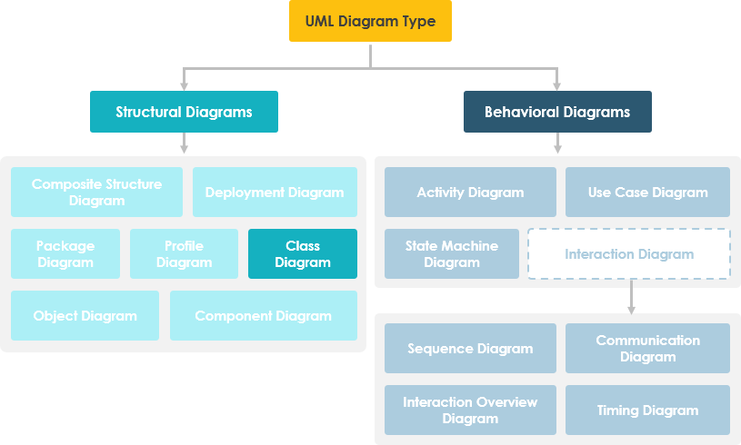
In software engineering, a class diagram in the Unified Modeling Language (UML) is a type of static structure diagram that describes the structure of a system by showing the system’s classes, their attributes, operations (or methods), and the relationships among objects.
The Real-World Value
From my experience, class diagrams serve four critical purposes:
-
Clarify system structure for developers during implementation
-
Document business rules for stakeholders who need to validate logic
-
Serve as a foundation for other UML diagrams (sequence, state, etc.)
-
Enable team alignment by creating a shared visual language
A UML class diagram is made up of:
-
A set of classes and
-
A set of relationships between classes
Getting Started: Creating Your First Class Diagram in Visual Paradigm
Creating a New Diagram
When I first opened Visual Paradigm, the interface felt intuitive. Here’s how to start:
-
Select Diagram > New from the application toolbar.
-
In the New Diagram window, select Class Diagram.
-
Click Next.
-
Enter the diagram name and description. The Location field enables you to select a model to store the diagram.
-
Click OK.
💡 Pro Tip: I always name diagrams with a prefix like “CD_” (Class Diagram) followed by the domain area (e.g., “CD_UserManagement”). This keeps my project navigator organized as diagrams multiply.
Creating Your First Class
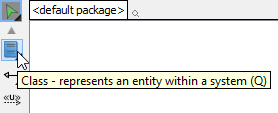
To create a class in a class diagram, click Class on the diagram toolbar and then click on the diagram.
 |
|---|
| Create class |
A class will be created.
 |
|---|
| Class created |
🎯 User Insight: Double-click the class name to edit it immediately. I use PascalCase for class names (e.g.,
UserProfile) to maintain consistency with C#/Java conventions.
Building Classes: Attributes, Operations, and Best Practices
Understanding Class Structure
A class notation consists of three parts:
-
Class Name – Appears in the first partition
-
Class Attributes – Shown in the second partition (with types after colons)
-
Class Operations – Services the class provides, shown in the third partition
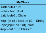
In this example:
-
MyClass has 3 attributes and 3 operations
-
Parameter p3 of op2 is of type int
-
op2 returns a float
-
op3 returns a pointer (denoted by a *) to Class6
Creating Attributes Efficiently
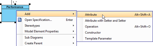
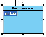
To create an attribute, right-click the class and select Add > Attribute from the pop-up menu.
 |
|---|
| Create attribute |
An attribute is created.
 |
|---|
| Attribute created |
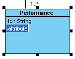
⚡ Speed Hack: The Enter Key Trick
After creating an attribute, press the Enter key—another attribute will be created automatically. This method allows you to create multiple attributes quickly and easily.
 |
|---|
| Create attribute with Enter key |
🔄 Workflow Tip: I batch-create all attributes first, then operations. This mirrors how I think about data before behavior.
Creating Operations
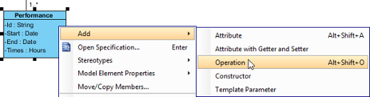
To create an operation, right-click the class and select Add > Operation from the pop-up menu.
 |
|---|
| Create operation |
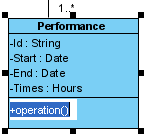
An operation is created.
 |
|---|
| Operation created |
Similar to creating attributes, you can press the Enter key to create multiple operations continuously.
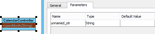
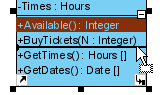
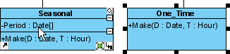
Showing Just a Parameter’s Type
When the name of a parameter starts with “unnamed_”, its name will not be displayed in the class shape, leaving only the parameter type (if defined).
 |
|---|
| Unnamed parameter |
🎨 Design Note: I use unnamed parameters for utility methods where parameter names don’t add clarity (e.g.,
calculateTotal(price: float, tax: float)becomescalculateTotal(: float, : float)).
Modeling Relationships: Associations, Generalizations, and Dependencies
Creating Associations Between Classes
To create an associated class in a class diagram:
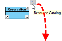
-
Move your mouse pointer over the source shape.
-
Press on the Resource Catalog button and drag it out.
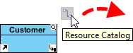
Using Resource Catalog -
Release the mouse button at the place where you want the class to be created. If you want to connect to an existing class, drop at that class. Otherwise, drop on the empty space.
-
If connecting to an existing class, select Association from Resource Catalog. If creating a new class, select Association -> Class. For aggregation/composition, choose those options instead.
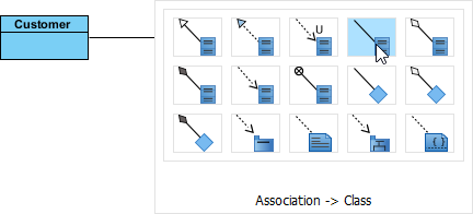
To create a class -
If creating a new class, enter its name and press Enter to confirm.
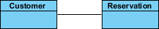
Associated class created
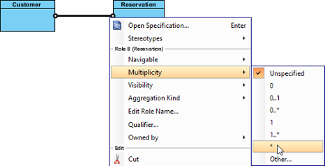
Editing Multiplicity and Direction
To edit multiplicity of an association end, right-click near the association end, select Multiplicity from the popup menu and then select a multiplicity.
 |
|---|
| Edit multiplicity |
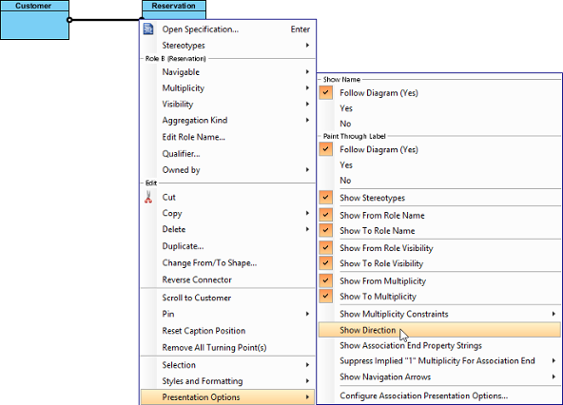
To show the direction of an association, right-click on it and select Presentation Options > Show Direction.
 |
|---|
| Show direction |
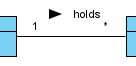
The direction arrow appears beside the association.
 |
|---|
| Direction shown |
🔍 Clarity Check: I always add direction arrows and meaningful relationship names (e.g., “contains”, “manages”) so non-technical stakeholders can read the diagram like a sentence.
Understanding Relationship Types
| Relationship Type | Graphical Representation |
|---|---|
Inheritance (Generalization):
|
 |
Simple Association:
|
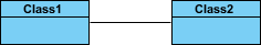 |
Aggregation:
|
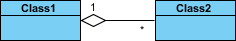 |
Composition:
|
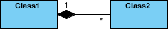 |
Dependency:
|
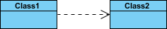 |
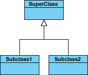
Creating Generalization (Inheritance)
To create a subclass:
-
Move your mouse pointer over the superclass.
-
Press on the Resource Catalog button and drag it out.
Using Resource Catalog -
Release the mouse button where you want the subclass. Connect to existing class or create new.
-
Select Generalization (existing class) or Generalization -> Class (new class).
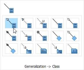
To create a subclass -
Enter the subclass name and press Enter.
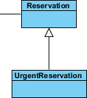
Subclass created
Creating Dependencies Between Class Members
You can add dependencies from/to attributes or operations:
-
Select Dependency from the diagram toolbar.

Selecting Dependency -
Press on the source shape or class member.
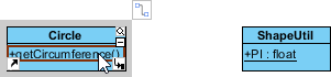
To press on the source operation -
Drag to the target shape or class member.
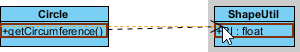
Dragging to target attribute -
Release to create the dependency.
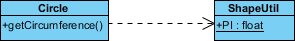
Dependency created between an operation and a member
⚠️ Common Mistake: Don’t overuse dependencies. I reserve them for cases where one class genuinely relies on another’s implementation details—not just for “uses” relationships.
Advanced Techniques: Enumerations, Generalization Sets, and Visibility Controls
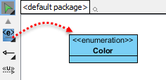
Creating Enumerations
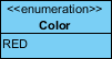
An enumeration is a special data type with predefined values (literals). Examples: Color (RED, GREEN, BLUE), Orientation (NORTH, SOUTH, EAST, WEST).
To create an enumeration, select Enumeration from the diagram toolbar and click on the diagram.
 |
|---|
| Create an enumeration |
To add an enumeration literal, right-click on the enumeration class and select Add > Enumeration Literal.
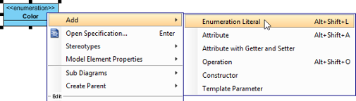 |
|---|
| Add an enumeration literal |
Enter the literal name and confirm.
 |
|---|
| Enumeration literal entered |
Managing Visibility of Attributes and Operations
UML identifies four visibility types: public (+), protected (#), private (-), and package (~).
Per Workspace (Global Setting)
-
Select Window > Project Options
-
Click Diagramming > Class tab > Presentation tab
-
Adjust Show attribute option and/or Show operation option
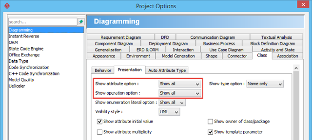
Show or hide operations
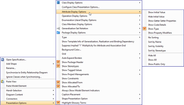
Per Diagram or Per Class
Right-click the diagram/class > Presentation Options > Attribute/Operation Display Options > Choose Hide All / Show All / Show Public Only.
 |
|---|
| Change the operations’ presentation options for classes in diagram |
For Specific Members
-
Right-click class > Presentation Options > Attributes/Operations > Customized…
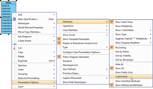
Show or hide specific class member -
Select Customized under Show dropdown
-
Move members to hide using > button
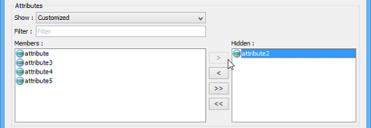
Select attributes to hide
🎯 Stakeholder Tip: When presenting to business audiences, I hide private/protected members and show only public operations. This reduces cognitive load and focuses discussion on interfaces, not implementation.
Setting Initial Values for Attributes
Initial values indicate defaults when objects are instantiated:
-
Right-click attribute > Open Specification…
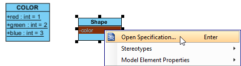
Opening the attribute specification -
In General tab, enter text value OR select a public static field from another class
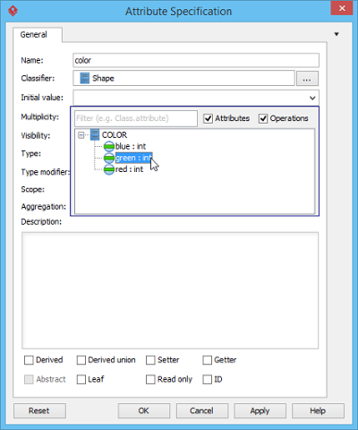
Selecting an initial value
⚠️ Note: To reference another class’s attribute as a default value, ensure it’s both static and public.
Working with Generalization Sets
A generalization set groups related inheritance relationships:
-
Select the generalizations to include
-
Right-click > Generalization set > Create Generalization Set…
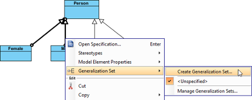
Create a generalization set -
Name the set in the dialog and click OK
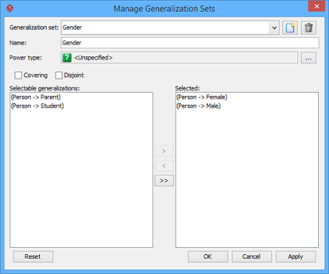
Name the generalization set -
Adjust connectors for clarity
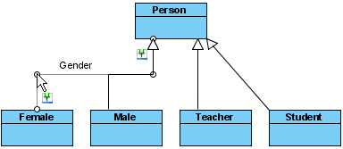
Adjust connector
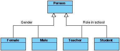 |
|---|
| Generalization sets defined |
Pro Tips: Efficiency Tricks and Workflow Optimization
Drag-and-Drop Class Member Management
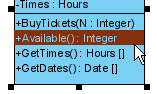
Reordering: Select a member and drag within its compartment. A thick black line shows the insertion point.
 |
|---|
| Reorder class member |
Release to confirm.
 |
|---|
| Class member reordered |
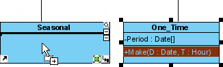
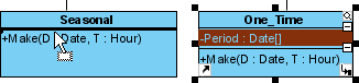
Copying: Select member + drag while holding Ctrl (plus sign appears in cursor).
 |
|---|
| Copy class member |
 |
|---|
| Class member copied |
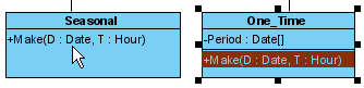
Moving: Drag without Ctrl key (no plus sign).
 |
|---|
| Move class member |
 |
|---|
| Class member moved |
Selecting All Class Members
Select any member first, then press Alt+A to select all others in the class.
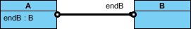
Setting Association End Ownership
Ownership may be indicated by a small dot. Right-click at the association end > Owned by > select association or opposite class.
 |
|---|
| Association end with ownership set |
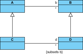
Subsetting on Association Ends
To define that one collection is a subset of another:
-
Right-click association > Open Specification…
-
In General tab, click … for the Role property of the target end
-
Open Subsetted Association Ends tab
-
Select the role to subset from the left list, click >
-
Confirm and show property strings via Presentation Options > Show Association End Property Strings
 |
|---|
| Subsetting on association end |
🔄 My Workflow: I create all classes first, then add relationships in batches by type (all associations, then all generalizations). This prevents the diagram from becoming a tangled mess mid-creation.
Leveraging AI: Modern Approaches to Class Diagramming
Building robust static structures no longer requires starting from scratch. Visual Paradigm’s AI ecosystem has transformed my workflow:
Multi-Platform AI Support
-
VP Desktop: Generate Class Diagrams via AI, then refine with professional modeling tools
-
AI Chatbot: Describe your domain at chat.visual-paradigm.com and get instant class structures
-
OpenDocs: Embed AI-generated diagrams directly into documentation at ai.visual-paradigm.com/tool/opendocs
Specialized AI Tools I Actually Use
⚡ AI Class Diagram Wizard: Step-by-step assistant for classes, attributes, and operations
🔄 Use Case Studio: Extracts domain classes from behavior descriptions
🚀 Agilien: Bridges User Stories/Epics directly to structural UML models
💾 DB Modeler AI: Generates conceptual Domain Class Diagrams for database design
🏛️ MVC Architecture: Creates specialized Controller Class Diagrams
Explore comprehensive guides:
AI Class Diagram Guide | Full AI Ecosystem
🤖 Honest Review: The AI tools excel at bootstrapping diagrams from natural language prompts. However, I still manually refine relationships and visibility settings—AI gets you 80% there; domain expertise delivers the final 20%.
Real-World Application: When to Use Single vs. Multiple Diagrams
Inevitably, modeling large systems means considering numerous entities. Should you use one massive diagram or multiple focused ones?
My recommendation: Always prefer multiple diagrams.
Why?
-
Cognitive load: Stakeholders can’t process 50+ classes on one canvas
-
Maintainability: Changes to one domain don’t require re-exporting a monolithic diagram
-
Collaboration: Different teams can own different diagrams (e.g., “CD_Payment”, “CD_UserAuth”)
-
Documentation: Smaller diagrams embed better in Confluence, wikis, or PDF reports
📐 Rule of Thumb: If a diagram requires scrolling in both directions to see all elements, it’s too big. Split it by bounded context or feature area.
Conclusion: Why Class Diagrams Still Matter in 2026
After years of using Visual Paradigm for class diagrams across startups and enterprise projects, here’s my takeaway: Class diagrams aren’t about perfect UML compliance—they’re about shared understanding.
The tool’s strength isn’t just in its comprehensive feature set (though the Resource Catalog and drag-and-drop member management are genuinely brilliant). It’s in how it supports iterative modeling: sketch quickly, refine deliberately, and communicate clearly.
What I Love
✅ Intuitive Resource Catalog for relationship creation
✅ Granular visibility controls for stakeholder-specific views
✅ AI integration that accelerates (not replaces) thoughtful design
✅ Cross-platform support (Desktop + Web + AI Chatbot)
Where to Be Cautious
⚠️ Don’t over-engineer early diagrams—start simple, add detail as needed
⚠️ Avoid showing all attributes/operations to non-technical audiences
⚠️ Remember: diagrams document decisions; they don’t replace conversations
Whether you’re documenting a microservice architecture, aligning product and engineering on domain models, or onboarding new team members, a well-crafted class diagram in Visual Paradigm remains one of the most efficient ways to turn ambiguity into alignment.
Ready to try it? Download Visual Paradigm Community Edition (free) and start modeling today.
Reference
- Class Diagram Feature Overview: Visual Paradigm’s official feature page detailing class diagram capabilities within their UML modeling tool.
- Visual Paradigm UML Tool Suite: Comprehensive overview of Visual Paradigm’s UML modeling features and supported diagram types.
- Unified Modeling Language (Wikipedia): Encyclopedic reference on UML standards, history, and diagram types.
- What is Class Diagram? – Introductory Guide: Beginner-friendly explanation of class diagram concepts, notation, and use cases.
- Visual Paradigm Tutorials Library: Collection of step-by-step tutorials to help users get started with Visual Paradigm and UML modeling.
- Visual Paradigm YouTube Channel: Official video tutorials, feature demonstrations, and modeling best practices.
- Visual Paradigm Know-How: Community-driven knowledge base with tips, tricks, Q&A, and solutions to common modeling challenges.
- Visual Paradigm Support Portal: Official support channel for product assistance, feature requests, and technical help.
- Download Visual Paradigm Community Edition: Free download page for the award-winning, fully-featured Community Edition of Visual Paradigm.
- Visual Paradigm AI Chatbot: AI-powered assistant for generating and refining UML diagrams through natural language prompts.
- OpenDocs with AI Integration: Tool for embedding AI-generated diagrams directly into living documentation pages.
- AI Class Diagram Wizard: Step-by-step AI assistant for generating class diagrams from textual requirements.
- Use Case Studio: AI tool that extracts domain classes and relationships from use case descriptions.
- Agilien Platform: Agile-focused tool that bridges user stories and epics to structural UML models.
- DB Modeler AI: AI-powered database modeling tool that generates conceptual class diagrams for schema design.
- MVC Architecture Generator: Specialized AI tool for generating Controller-focused class diagrams in MVC patterns.
- AI Class Diagram Generator Guide: Comprehensive guide to leveraging AI for class diagram creation in Visual Paradigm.
- Visual Paradigm AI Ecosystem Overview: Strategic guide to using Visual Paradigm’s full suite of AI-powered modeling tools.
This post is also available in Deutsch, Español, فارسی, Français, English, Bahasa Indonesia, 日本語, Polski, Portuguese, Ру́сский, Việt Nam, 简体中文 and 繁體中文.