


Introduction: Why Component Diagrams Matter in Modern Software Design
As someone who has navigated the complexities of software architecture for over a decade, I’ve come to appreciate the immense value of clear, visual documentation. Among the various UML diagram types, component diagrams hold a special place in my toolkit—they bridge the gap between abstract design concepts and tangible implementation details.

In this comprehensive review, I’ll share my firsthand experience working with component diagrams in Visual Paradigm, walking through not just the “how” but also the “why” behind effective component modeling. Whether you’re a seasoned architect or just starting your UML journey, this guide aims to provide practical insights you can apply immediately to your projects.
Understanding Component Diagrams: The Foundation
Component diagrams are essentially class diagrams that focus on a system’s components that often used to model the static implementation view of a system. In Unified Modeling Language (UML), a component diagram depicts how components are wired together to form larger components or software systems. In other words, component diagrams are used to visualize the organization and relationships among components in a system.
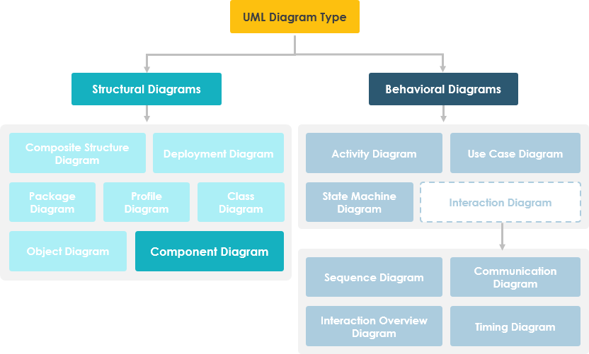
From my perspective, what makes component diagrams particularly powerful is their ability to break down complex systems into manageable, high-level functional units. Each component represents a clear responsibility within the entire system and interacts with other essential elements only on a need-to-know basis. It doesn’t describe what the system does, but rather which components enable those functionalities. This distinction is crucial for architectural planning and team communication.
Other Related Component Diagram Articles
Getting Started: Creating Your First Component Diagram in Visual Paradigm
Component diagram is a kind of UML diagram that shows the physical aspect of an object-oriented software system. It illustrates the architectures of the software components and dependencies between them.
Creating a Component Diagram: My Step-by-Step Workflow
When I first started using Visual Paradigm, I appreciated how intuitive the diagram creation process was. Here’s the workflow I now use consistently:
-
Select Diagram > New from the application toolbar.
-
In the New Diagram window, select Component Diagram.
-
Click Next.
-
Enter the diagram name and description. The Location field enables you to select a model to store the diagram.
-
Click OK.
Pro tip from my experience: Always use descriptive diagram names and include a brief description in the metadata. This small habit saves hours when revisiting projects months later or when onboarding new team members.
Creating Components: Building Your Architecture
To create a component in a component diagram, click Component on the diagram toolbar and then click on the diagram.
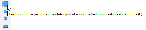
A component will be created.

In my projects, I typically start by identifying the major functional modules—authentication service, data access layer, API gateway, etc.—and represent each as a distinct component. This visual separation helps teams understand ownership boundaries and integration points.
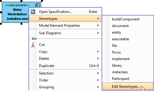
Assigning Stereotypes: Adding Semantic Clarity
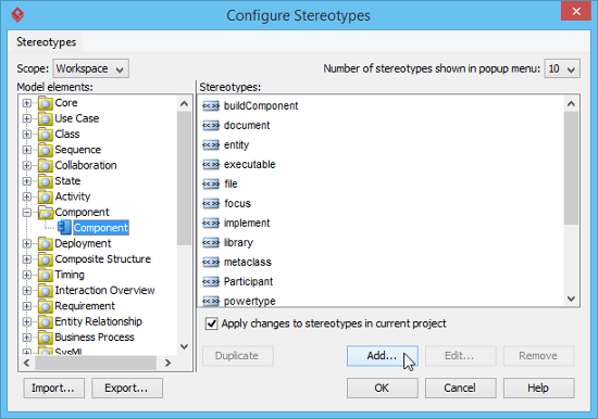
One feature I’ve grown to rely on is stereotype assignment. Right-click on the component and select Stereotypes > Edit Stereotypes… from the pop-up menu.
When the Component Specification window opens with the Stereotypes tab selected, the list on the left shows selectable stereotypes. If the stereotype you want to use isn’t on the list, click the Edit Stereotypes… button.
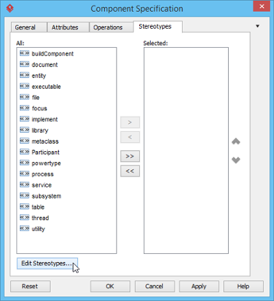
Click the Add… button in the Configure Stereotypes window.
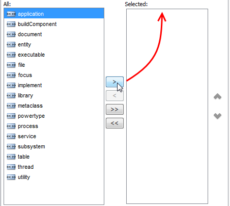
Name the stereotype (e.g., application) in the Stereotype Specification window and then click OK to close it. Click OK in the Configure Stereotypes window. The added stereotype will then appear on the list in the Component Specification window. Select it and click Add Selected button. Finally, click OK to confirm.
Close the specification window. Stereotypes will be applied to the component.
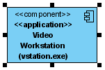
Why this matters: In my experience, stereotypes like <>, <>, or <> immediately communicate a component’s role to stakeholders without requiring lengthy documentation.
Modeling Interfaces: The Glue Between Components
Creating Provided Interfaces
To create a provided interface for a component:
-
Move your mouse pointer over the source component.
-
Press on the Resource Catalog button and drag it out.
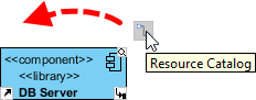
-
Release the mouse button at the place where you want the interface to be created.
-
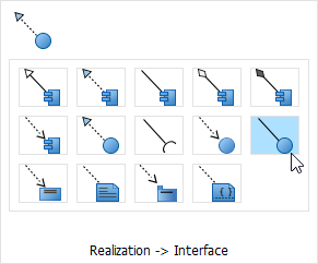
Select Realization -> Interface from Resource Catalog.
-
A new interface will be created and is connected to the source component. Enter its name and press Enter to confirm editing.

Creating Required Interfaces
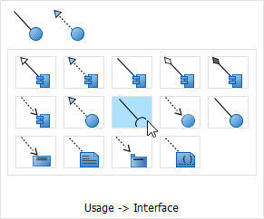
To create a required interface for a component, follow the same steps described above for creating a provided interface, but select Usage-> Interface in the Resource Catalog.
My workflow insight: I always model interfaces before dependencies. This “interface-first” approach forces me to think about contracts and boundaries, which leads to more loosely coupled, maintainable architectures.
Creating Dependencies: Mapping Component Relationships
To create a dependency, click Dependency on the diagram toolbar.
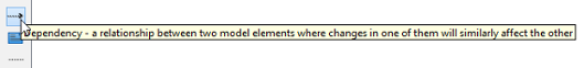
Drag from the source shape, move the mouse over the target shape, and then release the mouse button to create the dependency.
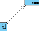
Continue to complete the diagram.
Practical tip: Use dependency arrows sparingly. In my reviews, I’ve found that diagrams with too many dependencies become visual noise. Focus on critical integration points that impact deployment or testing strategies.
Refining Presentation: Making Diagrams Communication-Ready
Showing/Hiding Attributes in Components
Per Diagram
You can add attributes to a component. To show/hide attributes for all components in a diagram:
-
Right-click on the background of the component diagram.
-
Select Presentation Options > Component Display Options from the popup menu.
-
Select/Deselect Show Attributes to cause attributes to be shown or hidden.
Per Component
To show/hide attributes for a specific component:
-
Right-click on the desired component.
-
Select Presentation Options > Show Attributes Mode from the popup menu.
-
Select Follow Diagram/Show All/Hide All/Customized… from the popup menu. If you’ve selected the Customized option, you can select specific attribute(s) to be shown or hidden.
Showing/Hiding Operations in Components
Per Diagram
You can add operations to a component. To show/hide operations for all components in a diagram:
-
Right-click on the background of the component diagram.
-
Select Presentation Options > Component Display Options from the popup menu.
-
Select/Deselect Show Operations to cause operations to be shown or hidden.
Per Component
To show/hide operations for a specific component:
-
Right-click on the desired component.
-
Select Presentation Options > Show Operations Mode from the popup menu.
-
Select Follow Diagram/Show All/Hide All/Customized… from the popup menu. If you’ve selected the Customized option, you can select specific operation(s) to be shown or hidden.
My presentation philosophy: I keep attributes and operations hidden in high-level architectural diagrams shown to executives, but reveal them in technical design reviews. Visual Paradigm’s granular display controls make this context-switching effortless.
Key Features That Enhanced My Workflow
Based on my hands-on experience, here are the Visual Paradigm capabilities that delivered the most value:
-
Modular Modeling: Represent self-contained units of software that can be independently replaced or upgraded within a system. This aligns perfectly with microservices architecture patterns I frequently implement.
-
Interface Visualization: Define Provided Interfaces (services a component offers, shown as a “lollipop” symbol) and Required Interfaces (services a component needs, shown as a “socket” symbol). These visual metaphors make contract-based design intuitive.
-
Relationship Management: Model dependencies, realizations, associations, and aggregations between various components and interfaces. The drag-and-drop Resource Catalog significantly speeds up this process.
-
AI-Powered Generation: Use the Visual Paradigm AI Chatbot to instantly brainstorm architectures and generate initial component diagrams from text descriptions. While I still refine the output manually, this feature accelerates the initial ideation phase remarkably.
-
Collaboration Tools: Facilitate team reviews and simultaneous editing through Visual Paradigm Online for remote work and online workshops. This has been invaluable for distributed teams.
Practical Tips from the Trenches
After creating dozens of component diagrams across multiple projects, here are my hard-earned recommendations:
-
Start high-level, then drill down: Begin with major subsystems, then decompose complex components in separate diagrams. Avoid the temptation to show everything on one canvas.
-
Name components by responsibility, not technology: Use “Payment Processing Service” rather than “StripeIntegrationModule.” This keeps your architecture resilient to technology changes.
-
Document interface contracts separately: While component diagrams show that interfaces exist, maintain detailed API specifications in complementary documentation.
-
Version your diagrams: Treat architectural diagrams like code—store them in version control and include change logs in descriptions.
-
Review with stakeholders early: Share preliminary diagrams with both technical and non-technical stakeholders. Visual Paradigm’s export options make this seamless.
Conclusion: Component Diagrams as Living Documentation
Component diagrams, when crafted thoughtfully in tools like Visual Paradigm, transcend static documentation—they become living artifacts that evolve alongside your system. My journey with these diagrams has taught me that their greatest value isn’t in perfect initial creation, but in their ability to facilitate ongoing conversations about system structure, integration points, and architectural evolution.
The combination of Visual Paradigm’s intuitive interface, robust feature set, and flexible presentation options has consistently helped me translate complex architectural concepts into clear, actionable visuals. Whether you’re designing a monolithic application or orchestrating a microservices ecosystem, mastering component diagrams is an investment that pays dividends in team alignment, onboarding efficiency, and long-term maintainability.
As software systems continue to grow in complexity, the ability to visualize and communicate component relationships becomes not just valuable, but essential. I encourage you to experiment with the techniques shared here, adapt them to your context, and discover how component diagrams can elevate your architectural practice.
References
-
What is Component Diagram?: Explains the fundamentals of component diagrams in UML, their purpose, and how they visualize system components.
-
What is UML?: Overview of Unified Modeling Language and its role in software design.
-
How to Draw Component Diagram in UML: Step-by-step tutorial for creating component diagrams in Visual Paradigm.
-
AI-Powered Component Diagram Generation: Feature guide for using AI to generate component diagrams from text descriptions.
-
Beginner’s Guide to Component Diagrams: Entry-level tutorial covering component diagram basics and best practices.
-
How to Draw Component Diagram Tutorial: Interactive tutorial with practical examples for drawing component diagrams.
-
Visual Paradigm Homepage: Main website for Visual Paradigm UML modeling tools and resources.
-
Component Diagram Video Tutorial: YouTube video demonstrating component diagram creation techniques.
-
Component Diagram Templates: Collection of pre-built templates for various component diagram scenarios.
-
Drawing Component Diagrams User Guide: Detailed user guide section on component diagram creation workflows.
-
How to Draw a Component Diagram in UML: Comprehensive documentation on component diagram drawing techniques.
-
Component Display Options: Guide for customizing component appearance and display settings.
-
Component Diagram Tutorial: Online interactive tutorial for learning component diagram fundamentals.
-
Free Component Diagram Tool: Information about Visual Paradigm’s free edition for creating component diagrams.
This post is also available in Deutsch, Español, فارسی, Français, English, Bahasa Indonesia, 日本語, Polski, Portuguese, Ру́сский, Việt Nam, 简体中文 and 繁體中文.