


BPMN—Business Process Model and Notation—is a standard visual language for describing how business processes work. It helps business users, analysts, developers, and managers understand the same process using consistent symbols.
The image summarizes five main BPMN areas:
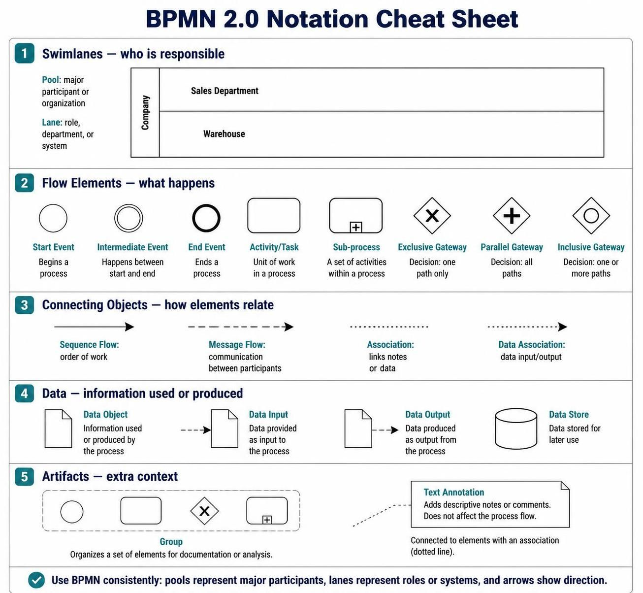
-
Swimlanes – who is responsible
-
Flow elements – what happens in the process
-
Connecting objects – how elements relate
-
Data – information used or produced
-
Artifacts – additional explanatory information
1. What BPMN Is Used For
BPMN can describe processes such as:
-
Processing a customer order
-
Approving an employee vacation request
-
Handling an insurance claim
-
Onboarding a new employee
-
Shipping products from a warehouse
-
Resolving a customer complaint
-
Approving an invoice
A BPMN diagram answers questions such as:
-
Who performs each activity?
-
What happens first?
-
What decisions are made?
-
Which activities happen in parallel?
-
What information is required?
-
What happens when an error occurs?
-
When does the process end?
A simple process might look like this:
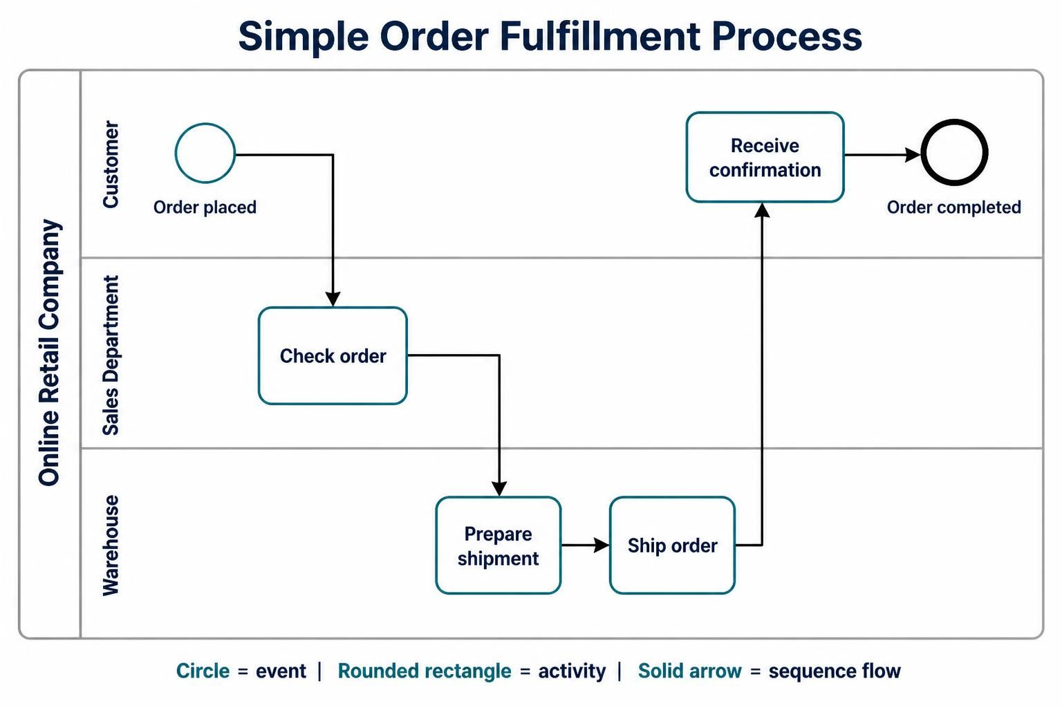
Customer places order
        ↓
Sales checks order
        ↓
Warehouse prepares shipment
        ↓
Order is shipped
        ↓
Customer receives confirmation
BPMN represents this process visually using events, tasks, gateways, flows, pools, and lanes.
2. BPMN Diagram Structure
A BPMN process usually contains four basic parts:
Start Event → Activity → Decision → Activity → End Event
For example:
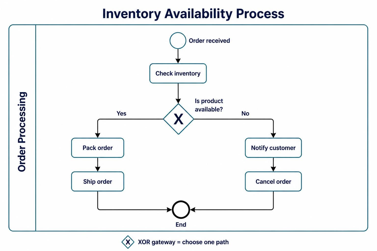
Order received
      ↓
Check inventory
      ↓
Is product available?
   ↙              ↘
 Yes              No
  ↓                ↓
Pack order     Notify customer
  ↓                ↓
Ship order     Cancel order
   ↘              ↙
       End
The main elements are described below.
3. Swimlanes: Pools and Lanes
Swimlanes organize responsibility. They show which participant, department, role, or system performs each activity.
Pools
A pool represents a major participant in a process.
A participant might be:
-
A company
-
A customer
-
A supplier
-
A bank
-
A government agency
-
An external software system
Example:
Pool: Online Retail Company
A pool can contain one or more lanes.
A pool may also be shown as a collapsed box when the internal process is not being modeled.
Lanes
A lane is a subdivision inside a pool. It normally represents:
-
A department
-
A job role
-
A team
-
A system
-
A business function
Example:
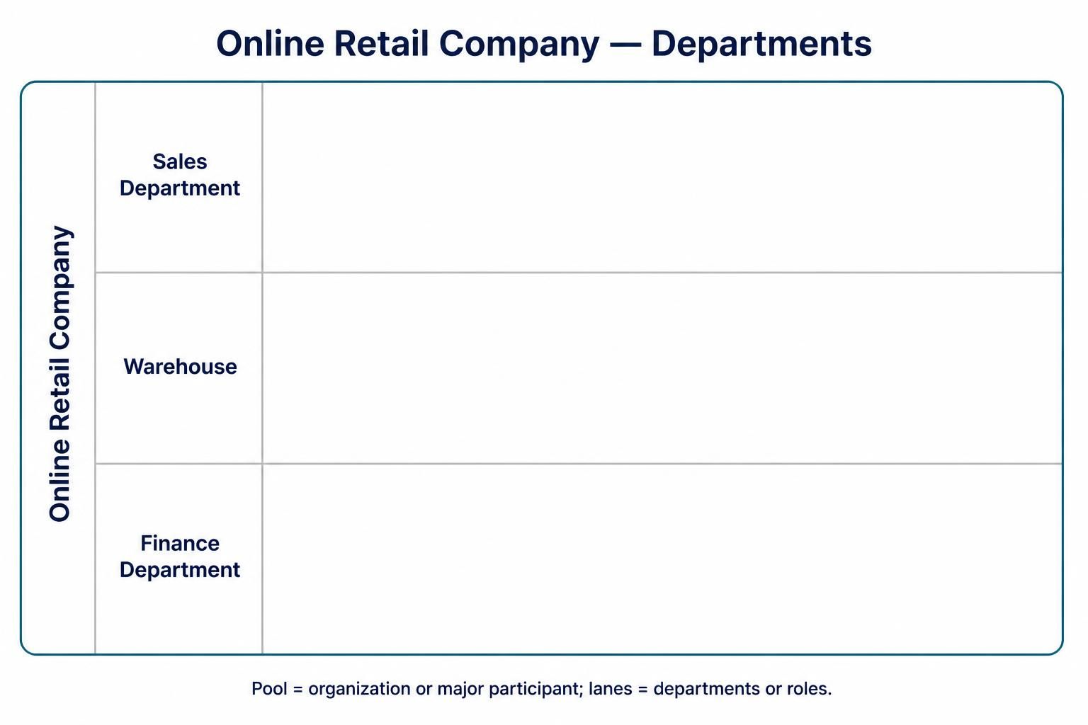
Pool: Online Retail Company
 ├── Sales Department
 ├── Warehouse
 └── Finance Department
A process might be organized like this:
| Lane | Responsibility |
|---|---|
| Customer | Places the order and receives notifications |
| Sales Department | Reviews and confirms the order |
| Warehouse | Picks, packs, and ships products |
| Finance Department | Processes payment |
| Delivery Partner | Delivers the package |
Example with lanes
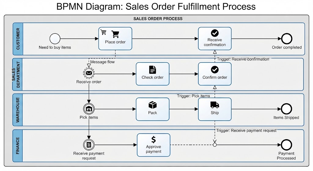
Customer          | Place order ─────────────── Receive confirmation
                  |
Sales Department  | Receive order → Check order → Confirm order
                  |
Warehouse         |                         Pick items → Pack → Ship
                  |
Finance           | Receive payment request → Approve payment
The position of an activity in a lane indicates who is responsible for it.
Pool versus lane
| Element | Meaning | Typical example |
|---|---|---|
| Pool | Major participant or organization | Customer, Supplier, Bank |
| Lane | Role, department, or system within a participant | Sales, Warehouse, Finance |
Beginner rule
Use a pool when the participant is organizationally or operationally separate. Use a lane when the participant is a role or group inside that pool.
4. Flow Elements
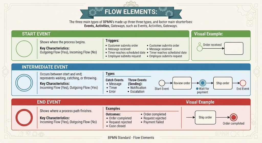
Flow elements describe what happens in the process. The three main types are:
-
Events
-
Activities
-
Gateways
4.1 Events
An event represents something that happens during a process. Events do not usually describe work being performed; instead, they indicate that something starts, interrupts, or ends the process.
Events are represented by circles.
Start event
A start event shows where the process begins.
Symbol: thin-lined circle
Examples:
-
Customer submits an order
-
A message is received
-
A timer reaches a scheduled date
-
An employee submits a request
Example:
○ Order received
A start event should normally have outgoing flow but no incoming sequence flow.
Intermediate event
An intermediate event occurs between the start and end of a process.
Symbol: double-lined circle
It can represent:
-
Waiting for a message
-
Waiting for a timer
-
Catching an error
-
Sending a notification
-
Escalating a problem
Example:
Start → Review order → ◉ Wait for payment → Ship order
An intermediate event can either:
-
Catch something, such as waiting for an incoming message
-
Throw something, such as sending a message or raising an error
End event
An end event shows where a process path finishes.
Symbol: thick-lined circle
Examples:
-
Order completed
-
Request rejected
-
Payment failed
-
Case closed
Example:
Ship order → ● Order completed
An end event normally has incoming sequence flow but no outgoing sequence flow.
4.2 Activities
An activity represents work performed in the process. Activities are shown as rounded rectangles.
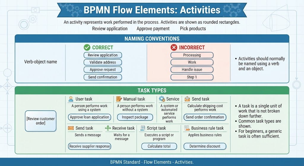
Examples:
-
Review application
-
Approve payment
-
Pick products
-
Send invoice
-
Update customer record
Activities should normally be named using a verb and an object:
-
Review application
-
Validate address
-
Approve request
-
Send confirmation
Avoid vague names such as:
-
Processing
-
Work
-
Handle issue
-
Step 1
Task
A task is a single unit of work that is not broken down further in the current diagram.
Example:
[Review customer order]
A task can be performed manually, automatically, or by a user working with a system.
Common BPMN task types include:
| Task type | Meaning | Example |
|---|---|---|
| User task | A person performs work using a system | Approve loan application |
| Manual task | A person performs work without a system | Inspect package |
| Service task | A system or automated service performs work | Calculate shipping cost |
| Send task | Sends a message | Send order confirmation |
| Receive task | Waits for a message | Receive supplier response |
| Script task | Executes a script or program | Calculate total |
| Business rule task | Applies business rules | Determine discount |
For beginners, a normal generic task is often sufficient unless the exact implementation matters.
Sub-process
A sub-process is a group of activities treated as one larger activity.
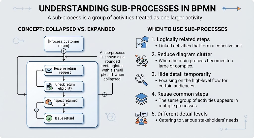
Example:
[Process customer return]
Inside the sub-process might be:
Receive return request
      ↓
Check return eligibility
      ↓
Inspect returned item
      ↓
Issue refund
Use a sub-process when:
-
The group of activities is logically related
-
The diagram is becoming too large
-
You want to hide detail temporarily
-
The same group of steps is reused
-
Different people need different levels of detail
A sub-process is shown as a rounded rectangle with a small plus sign when collapsed.
4.3 Gateways
A gateway controls how the process branches, merges, or makes decisions. Gateways are represented by diamonds.
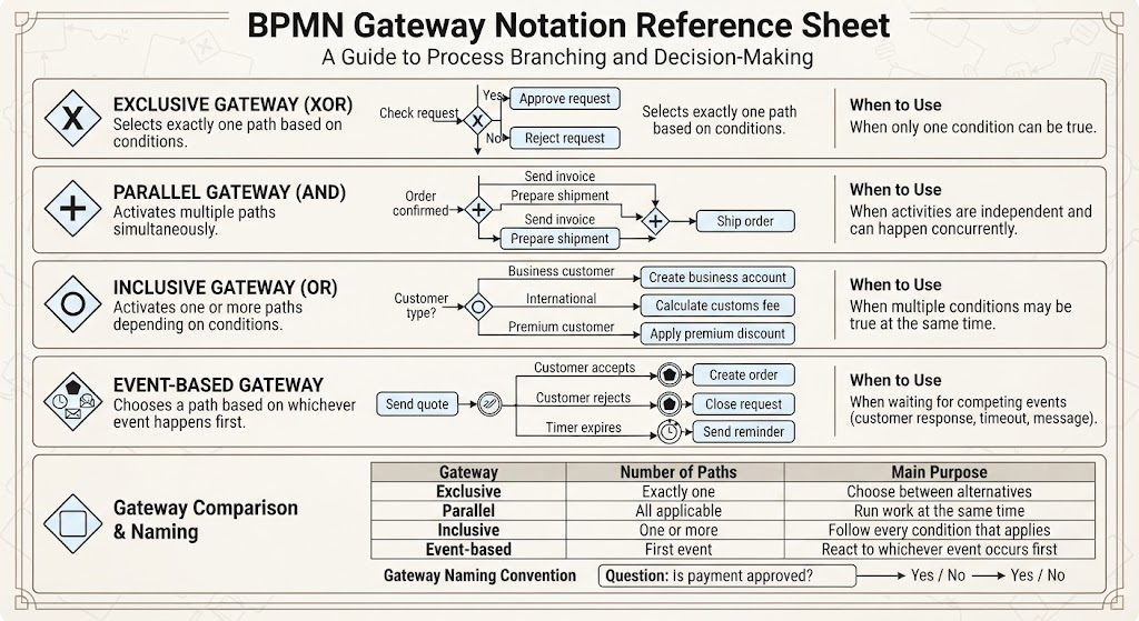
The symbol inside the diamond indicates the gateway type.
Exclusive gateway: XOR
An exclusive gateway selects exactly one path.
Example:
                 ┌── Yes → Approve request
Check request ─◇─┤
                 └── No  → Reject request
Use an exclusive gateway when only one condition can be true.
Example question:
Is the order value greater than $1,000?
Possible paths:
-
Yes: Require manager approval
-
No: Continue automatically
Typical notation:
◇ Is payment approved?
Only one outgoing path should be followed.
Parallel gateway: AND
A parallel gateway activates multiple paths at the same time.
Example:
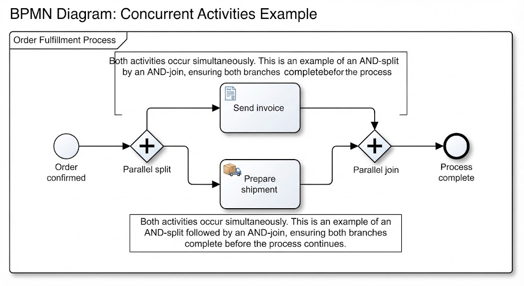
                 ┌── Send invoice
Order confirmed ─◇
                 └── Prepare shipment
Both activities occur.
A parallel gateway can also synchronize parallel paths:
Send invoice ────┐
                 ◇── Ship order
Prepare shipment ┘
The process continues only after both branches are complete.
Use a parallel gateway when activities are independent and can happen concurrently.
Inclusive gateway: OR
An inclusive gateway activates one or more paths depending on conditions.
Example:
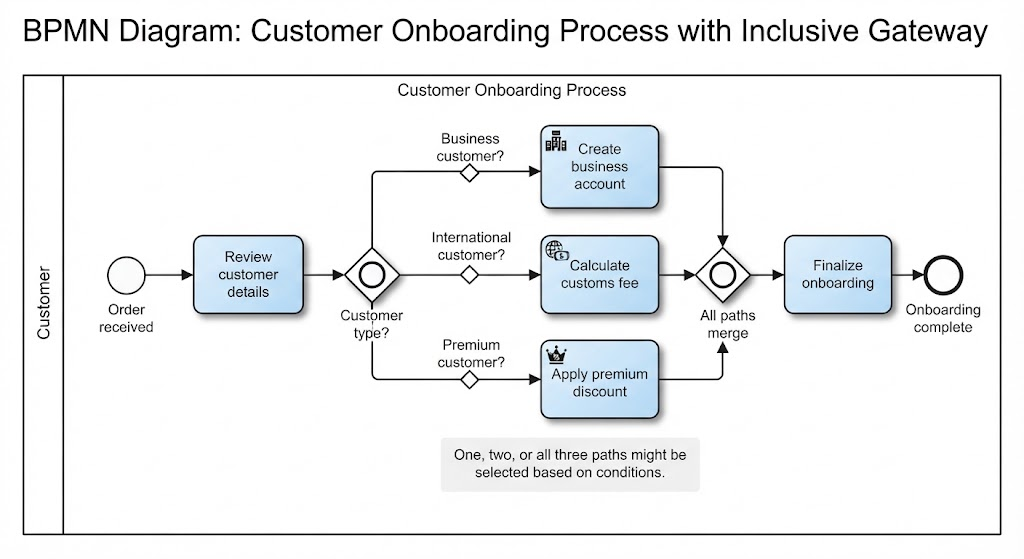
Customer type?
   ├── Business customer → Create business account
   ├── International     → Calculate customs fee
   └── Premium customer  → Apply premium discount
One, two, or all three paths might be selected.
Use an inclusive gateway when multiple conditions may be true at the same time.
Event-based gateway
An event-based gateway chooses a path based on whichever event happens first.
Example:
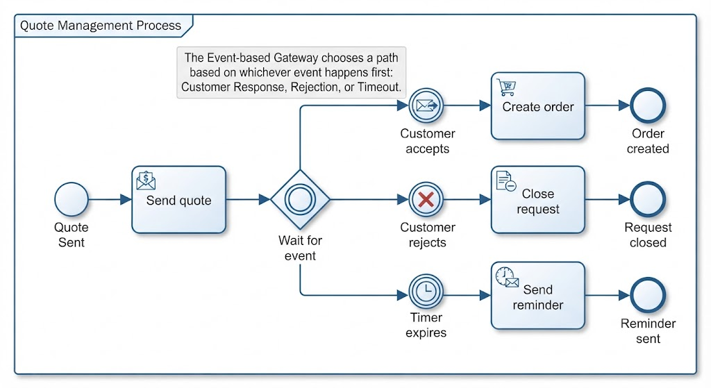
Send quote
    ↓
◇ Wait for event
   ├── Customer accepts → Create order
   ├── Customer rejects → Close request
   └── Timer expires    → Send reminder
This is useful when the process waits for competing events, such as:
-
A customer response
-
A timeout
-
A message from another system
Gateway comparison
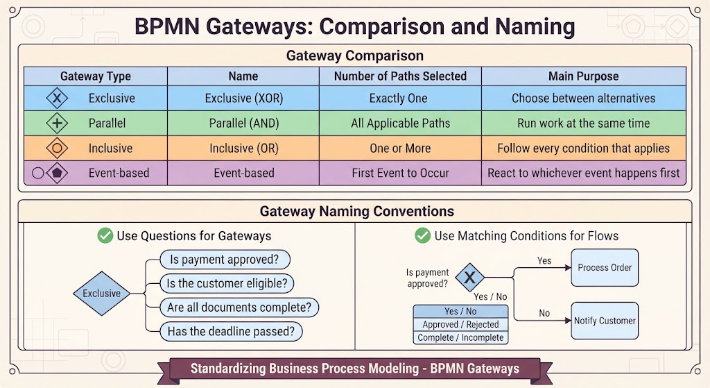
| Gateway | Number of paths selected | Main purpose |
|---|---|---|
| Exclusive | Exactly one | Choose between alternatives |
| Parallel | All applicable paths | Run work at the same time |
| Inclusive | One or more | Follow every condition that applies |
| Event-based | First event to occur | React to whichever event happens first |
Gateway naming
A gateway can be written as a question:
-
Is payment approved?
-
Is the customer eligible?
-
Are all documents complete?
-
Has the deadline passed?
The outgoing flows should then use matching conditions:
-
Yes / No
-
Approved / Rejected
-
Complete / Incomplete
5. Connecting Objects
Connecting objects show how BPMN elements relate to one another.
5.1 Sequence flow
A sequence flow shows the order in which activities, events, and gateways occur.
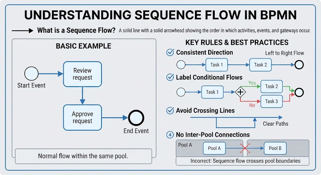
It is represented by a solid line with a solid arrowhead.
Start → Review request → Approve request → End
Sequence flow is normally used within the same pool.
Example:
○ Start → [Validate order] → ◇ Payment approved?
Rules for sequence flow
-
Use arrows to show direction.
-
Keep the direction consistent, usually left to right or top to bottom.
-
Label conditional flows when necessary.
-
Avoid crossing lines.
-
Do not use sequence flow to connect separate pools.
5.2 Message flow
A message flow shows communication between separate participants or pools.
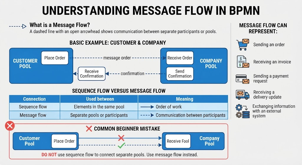
It is represented by a dashed line with an open arrowhead.
Example:
Customer Pool       - - - message order - - -> Company Pool
Company Pool        - - - confirmation - - -> Customer Pool
Message flow can represent:
-
Sending an order
-
Receiving an invoice
-
Sending a payment request
-
Receiving a delivery update
-
Exchanging information with an external system
Sequence flow versus message flow
| Connection | Used between | Meaning |
|---|---|---|
| Sequence flow | Elements in the same pool | Order of work |
| Message flow | Separate pools or participants | Communication between participants |
A common beginner mistake is using sequence flow across two pools. Use message flow instead.
5.3 Association
An association links additional information to a BPMN element.
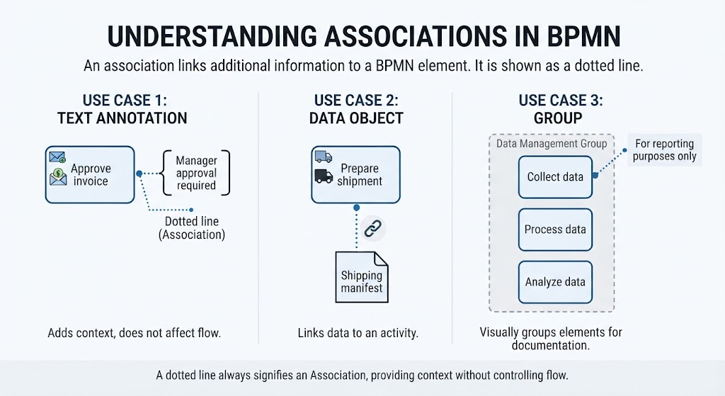
It is shown as a dotted line.
Use it to connect:
-
A text annotation to an activity
-
A data object to a task
-
A group to related elements
Example:
[Approve invoice] ······· “Manager approval required”
An association does not control the order of the process. It simply adds context.
5.4 Data association
A data association shows how data enters or leaves an activity.
It can show:
-
An input document being used
-
An output document being produced
-
Information being updated
-
Data being stored
Example:
[Create invoice] ─ ─ ─ → Invoice document
The line is usually dotted with an open arrowhead.
6. Data Elements
BPMN data elements show information used or created by the process.
6.1 Data object
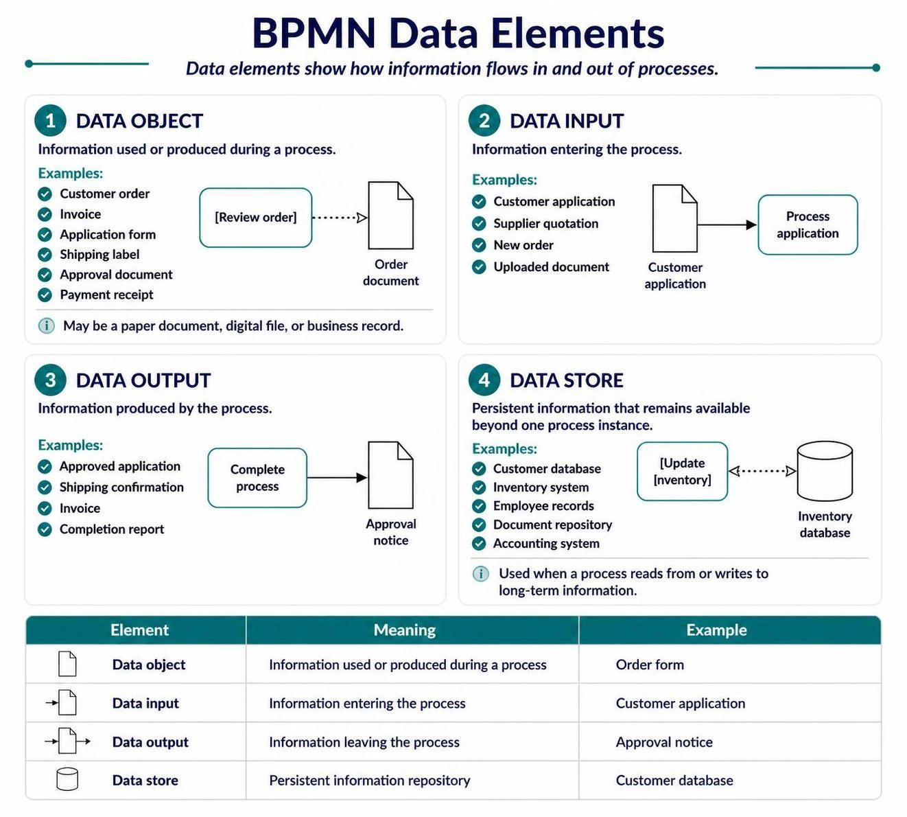
A data object represents information used or produced during a process.
Examples:
-
Customer order
-
Invoice
-
Application form
-
Shipping label
-
Approval document
-
Payment receipt
Example:
[Review order] ─ ─ ─ → Order document
A data object does not necessarily mean a physical paper document. It may also represent a digital file or business record.
6.2 Data input
A data input represents information entering the process.
Examples:
-
Customer application
-
Supplier quotation
-
New order
-
Uploaded document
Example:
Customer application → Process application
6.3 Data output
A data output represents information produced by the process.
Examples:
-
Approved application
-
Shipping confirmation
-
Invoice
-
Completion report
6.4 Data store
A data store represents persistent information that remains available beyond one process instance.
Examples:
-
Customer database
-
Inventory system
-
Employee records
-
Document repository
-
Accounting system
Example:
[Update inventory] ─ ─ ─ ↔ Inventory database
A data store is useful when the process reads from or writes to a long-term information repository.
Data element comparison
| Element | Meaning | Example |
|---|---|---|
| Data object | Information used or produced during a process | Order form |
| Data input | Information entering the process | Customer application |
| Data output | Information leaving the process | Approval notice |
| Data store | Persistent information repository | Customer database |
7. Artifacts
Artifacts add information without changing the process flow.
The image shows two common artifacts: groups and text annotations.
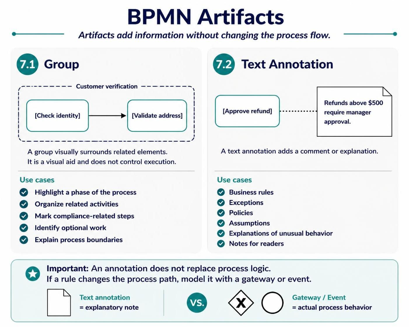
7.1 Group
A group visually surrounds related elements.
A group is shown using a dashed rounded rectangle.
Use a group to:
-
Highlight a phase of the process
-
Organize related activities
-
Mark compliance-related steps
-
Identify optional work
-
Explain process boundaries
Example:
┌ - - - - - Customer verification - - - - - ┐
  [Check identity] → [Validate address]
└ - - - - - - - - - - - - - - - - - - - - -┘
A group does not control execution. It is only a visual aid.
7.2 Text annotation
A text annotation adds a comment or explanation.
Example:
[Approve refund] ····· “Refunds above $500 require manager approval.”
Annotations are helpful for:
-
Business rules
-
Exceptions
-
Policies
-
Assumptions
-
Explanations of unusual behavior
-
Notes for readers
Do not use text annotations as a replacement for actual BPMN logic. If a rule changes the process path, model it with a gateway or event.
8. Complete Example: Online Order Process
The following example combines pools, lanes, activities, gateways, data, and messages.
Scenario
A customer places an online order. The company checks inventory and payment. If the product is available and payment is approved, the warehouse ships the order. Otherwise, the customer is notified.
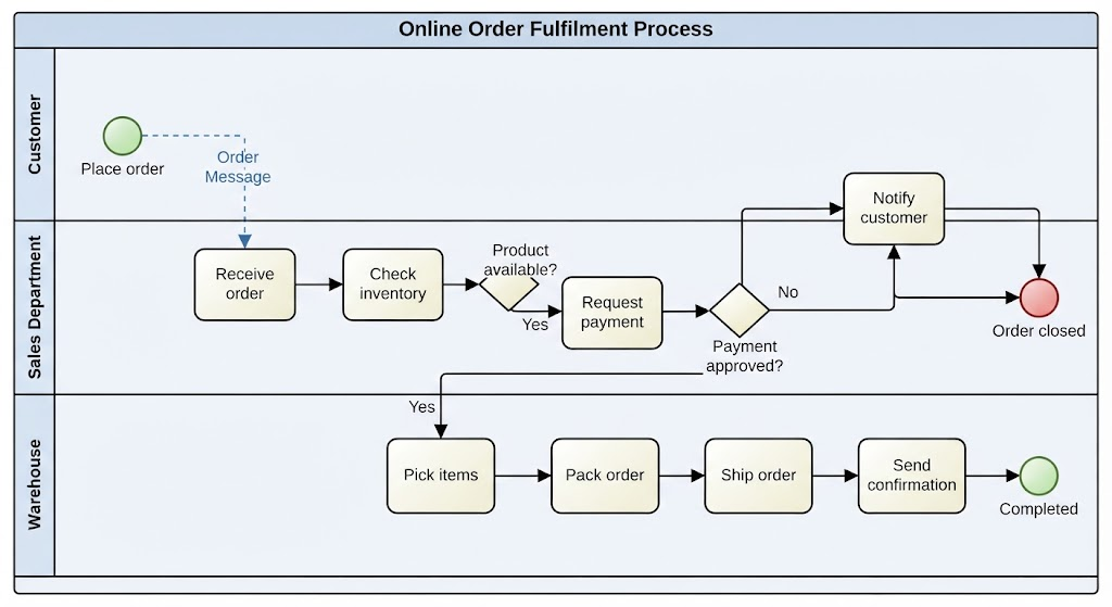
Customer
  ○ Place order
        |
        | Order message
        v

Online Store
  Sales Department
  ○ Receive order
        ↓
  [Check inventory]
        ↓
  ◇ Product available?
     ↙              ↘
   No                Yes
   ↓                  ↓
[Notify customer]  [Request payment]
   ↓                  ↓
  ● Order closed   ◇ Payment approved?
                     ↙              ↘
                   No                Yes
                   ↓                  ↓
             [Notify customer]   Warehouse
                   ↓             [Pick items]
              ● Order closed          ↓
                                  [Pack order]
                                       ↓
                                  [Ship order]
                                       ↓
                                  [Send confirmation]
                                       ↓
                                      ● Completed
Data used in the process
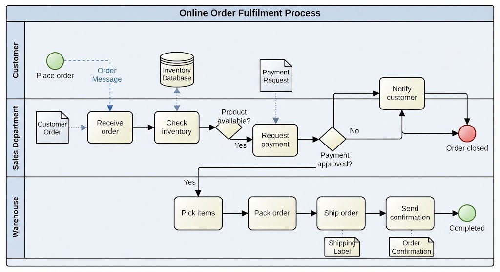
Customer order → Receive order
Inventory database ↔ Check inventory
Payment request → Request payment
Shipping label → Ship order
Order confirmation → Send confirmation
Communication between participants
-
Customer sends an order to the company.
-
Company sends a payment request to the payment provider.
-
Payment provider sends an approval or rejection message.
-
Company sends a confirmation to the customer.
-
Warehouse receives a shipment request.
9. Example: Employee Vacation Request
Business rule
An employee submits a vacation request. The manager approves or rejects it. If approved, the HR system updates the employee’s leave balance.
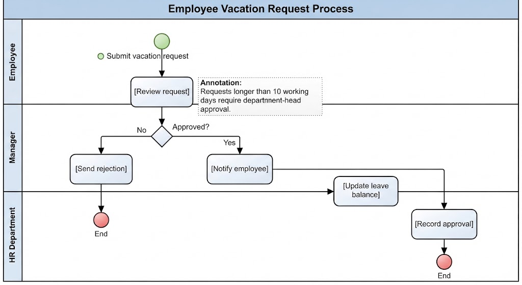
Employee
  ○ Submit vacation request
        ↓
Manager
  [Review request]
        ↓
  ◇ Approved?
    ↙       ↘
  No         Yes
  ↓           ↓
[Send       [Notify employee]
 rejection]       ↓
  ↓         HR Department
  ● End      [Update leave balance]
                    ↓
               [Record approval]
                    ↓
                   ● End
Possible data elements
-
Vacation request
-
Employee leave balance
-
Approval notification
-
HR record
Possible annotation
“Requests longer than 10 working days require department-head approval.”
If the rule creates another decision path, it should be modeled with a gateway rather than only written as an annotation.
10. Example: Parallel Activities
Suppose an approved loan application requires both a credit check and an identity check. These can happen at the same time.
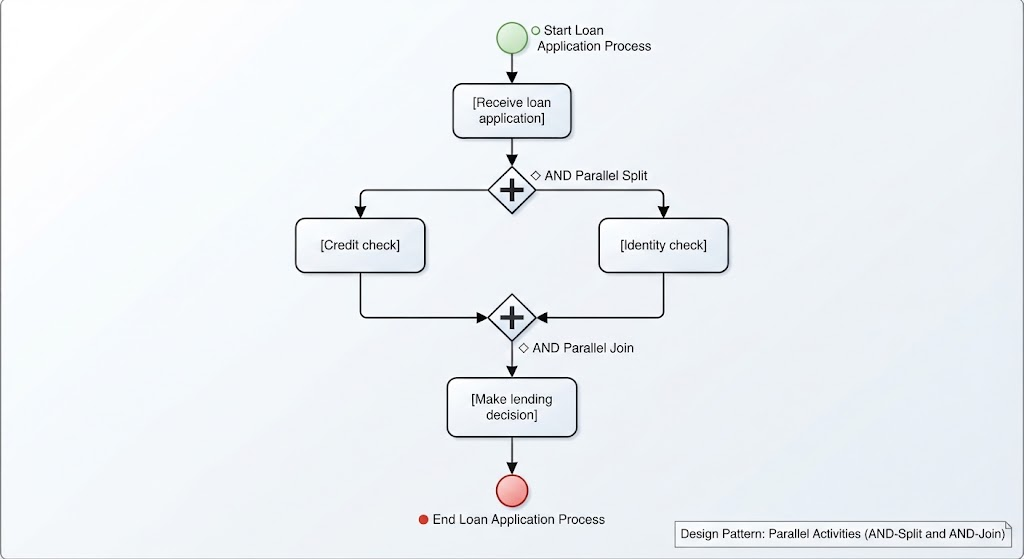
[Receive loan application]
          ↓
       ◇ AND
       ↙   ↘
[Credit check] [Identity check]
       ↘   ↙
       ◇ AND
          ↓
 [Make lending decision]
          ↓
         ● End
The first parallel gateway splits the process. The second waits until both activities are complete.
Use this pattern when:
-
Activities are independent
-
Both activities are required
-
Performing them simultaneously saves time
11. Example: Waiting for Events
A supplier sends a quotation, but the company may also cancel the request if the response takes too long.
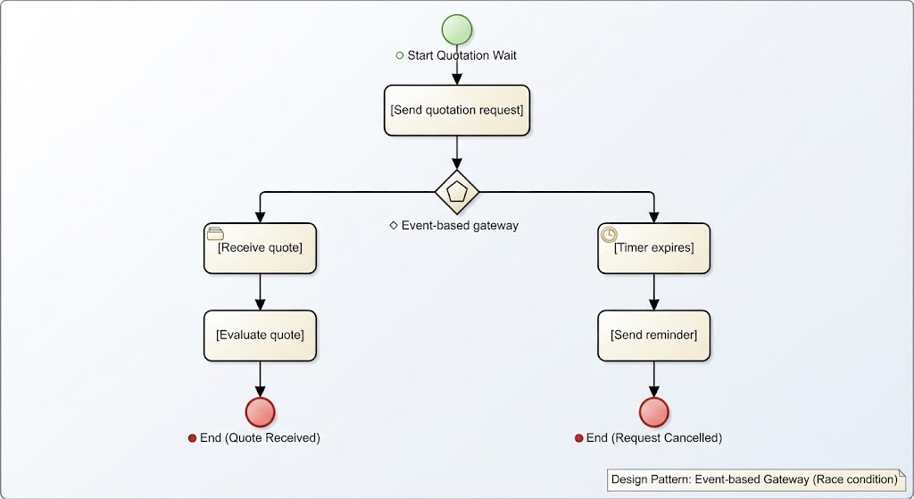
[Send quotation request]
          ↓
  ◇ Event-based gateway
      ↙          ↘
[Receive quote]  [Timer expires]
      ↓              ↓
[Evaluate quote]  [Send reminder]
      ↓              ↓
     ● End          ● End
The path depends on which event happens first.
12. How to Create a BPMN Diagram
Follow this process when modeling a new business process.
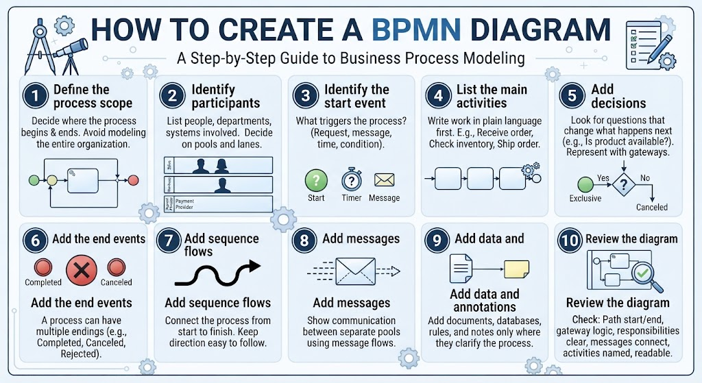
Step 1: Define the process scope
Decide where the process begins and ends.
Example:
-
Start: Customer submits an order
-
End: Order is shipped or canceled
Avoid modeling the entire organization in one diagram.
Step 2: Identify participants
List the people, departments, organizations, and systems involved.
Example:
-
Customer
-
Sales department
-
Warehouse
-
Payment provider
Decide which should be pools and which should be lanes.
Step 3: Identify the start event
Ask:
What triggers this process?
Possible answers:
-
A request is submitted
-
A message arrives
-
A scheduled time occurs
-
A condition becomes true
Step 4: List the main activities
Write the work in plain language first.
Example:
-
Receive order
-
Check inventory
-
Request payment
-
Pick products
-
Pack order
-
Ship order
-
Send confirmation
Step 5: Add decisions
Look for questions that change what happens next.
Examples:
-
Is the product available?
-
Is payment approved?
-
Is the request complete?
-
Has the deadline passed?
Represent these decisions with gateways.
Step 6: Add the end events
A process may have multiple endings.
Examples:
-
Order completed
-
Order canceled
-
Request rejected
-
Payment failed
Step 7: Add sequence flows
Connect the process from start to finish. Keep the direction easy to follow.
Step 8: Add messages
Show communication between separate pools using message flows.
Step 9: Add data and annotations
Add documents, databases, rules, and notes only where they clarify the process.
Step 10: Review the diagram
Check whether:
-
Every process path starts correctly
-
Every path reaches an end
-
Gateways are logically paired
-
Responsibilities are clear
-
Messages connect separate participants
-
Activities are named consistently
-
The diagram is readable
13. Naming Conventions
Good names make BPMN diagrams much easier to understand.
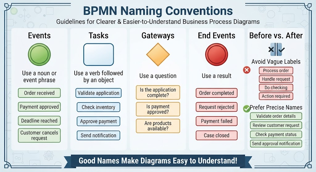
Events
Use a noun or event phrase:
-
Order received
-
Payment approved
-
Deadline reached
-
Customer cancels request
Tasks
Use a verb followed by an object:
-
Validate application
-
Check inventory
-
Approve payment
-
Send notification
Gateways
Use a question:
-
Is the application complete?
-
Is payment approved?
-
Are products available?
End events
Use a result:
-
Order completed
-
Request rejected
-
Payment failed
-
Case closed
Avoid vague labels such as:
-
Process order
-
Handle request
-
Do checking
-
Action required
Prefer more precise names:
-
Validate order details
-
Review customer request
-
Check payment status
-
Send approval notification
14. Common Beginner Mistakes
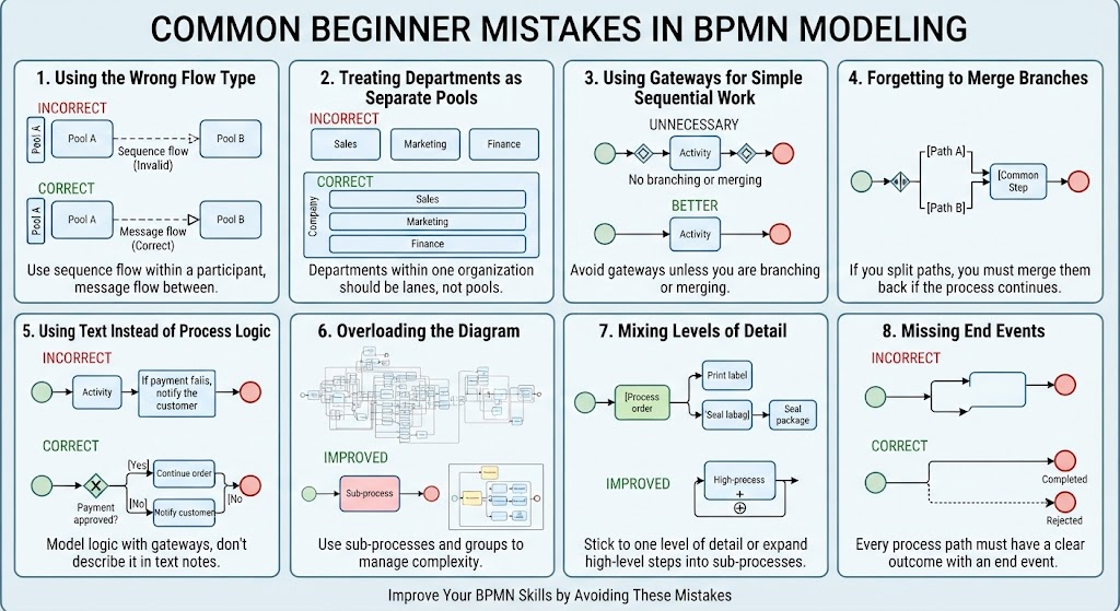
Using the wrong flow type
Incorrect:
Sequence flow between two separate pools
Correct:
Message flow between separate pools
Use sequence flow for the order of activities within a participant. Use message flow for communication between participants.
Treating every department as a separate pool
Departments within the same organization are usually better represented as lanes within one pool. Separate pools are more suitable for independent participants.
Using gateways for simple sequential work
Do not add a gateway when there is no branching or merging.
Unnecessary:
Start → ◇ → Review form → ◇ → End
Better:
Start → Review form → End
Forgetting to merge branches
If a gateway splits the process, its branches may need to be merged later.
For example, after either approving or rejecting a request, the process might continue to a common notification step.
Using text instead of process logic
Writing “If payment fails, notify the customer” as a note does not model the behavior. Use an exclusive gateway:
◇ Payment approved?
   ├── Yes → Continue order
   └── No  → Notify customer
Overloading the diagram
A diagram with too many details becomes difficult to read. Use:
-
Sub-processes
-
Separate diagrams
-
Groups
-
More specific views for different audiences
Mixing levels of detail
Avoid placing a high-level activity such as “Process order” beside detailed steps such as “Print label” and “Seal package” unless the relationship is clear.
Choose one level of detail for the diagram or use a sub-process.
Missing end events
A process should normally make its possible outcomes clear. Include end events for successful, rejected, canceled, or failed paths where appropriate.
15. BPMN Modeling Best Practices
-
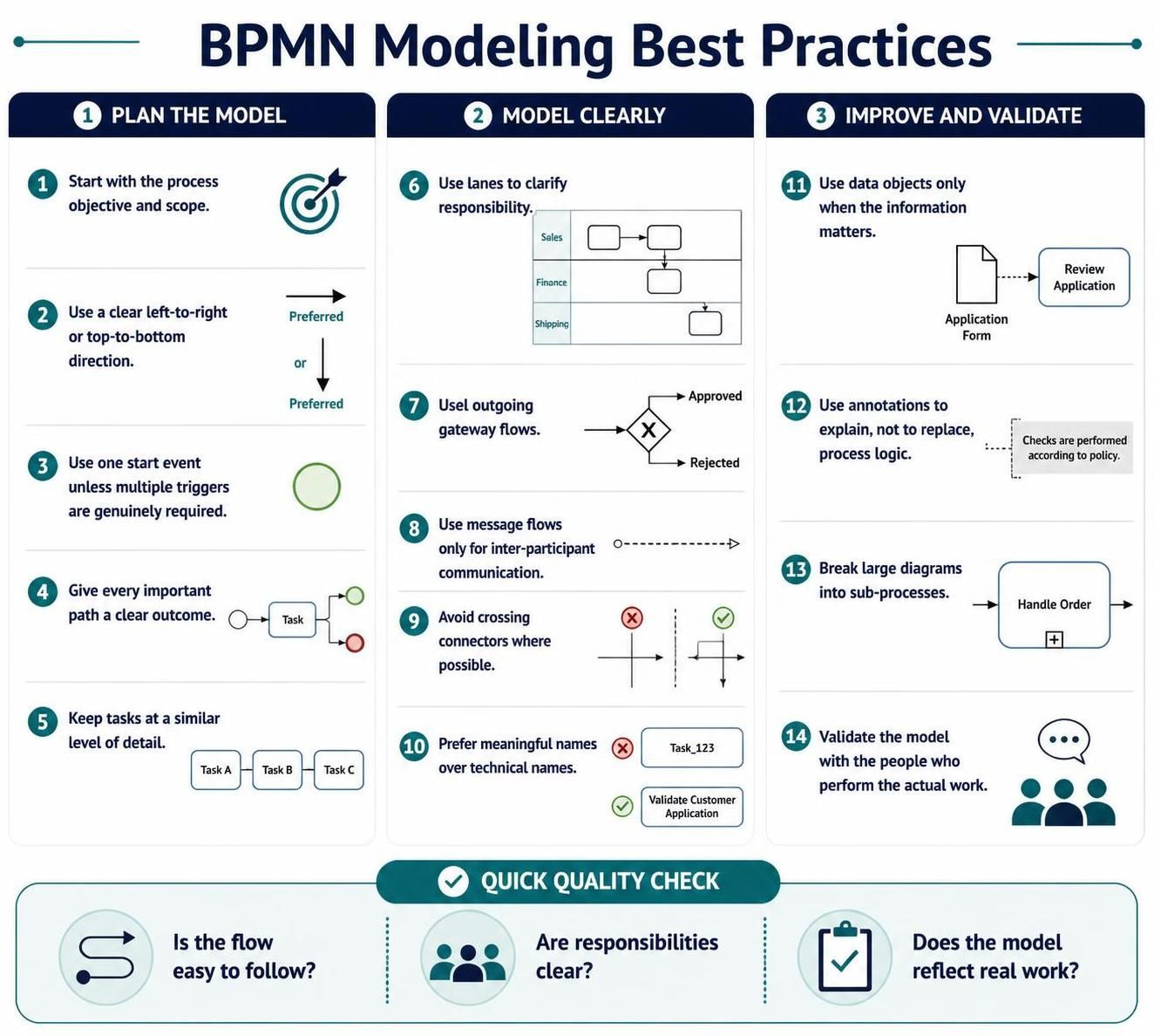
Start with the process objective and scope.
-
Use a clear left-to-right or top-to-bottom direction.
-
Use one start event unless multiple triggers are genuinely required.
-
Give every important path a clear outcome.
-
Keep tasks at a similar level of detail.
-
Use lanes to clarify responsibility.
-
Label outgoing gateway flows.
-
Use message flows only for inter-participant communication.
-
Avoid crossing connectors where possible.
-
Prefer meaningful names over technical names.
-
Use data objects only when the information matters.
-
Use annotations to explain, not to replace, process logic.
-
Break large diagrams into sub-processes.
-
Validate the model with the people who perform the actual work.
16. Quick BPMN Cheat Sheet
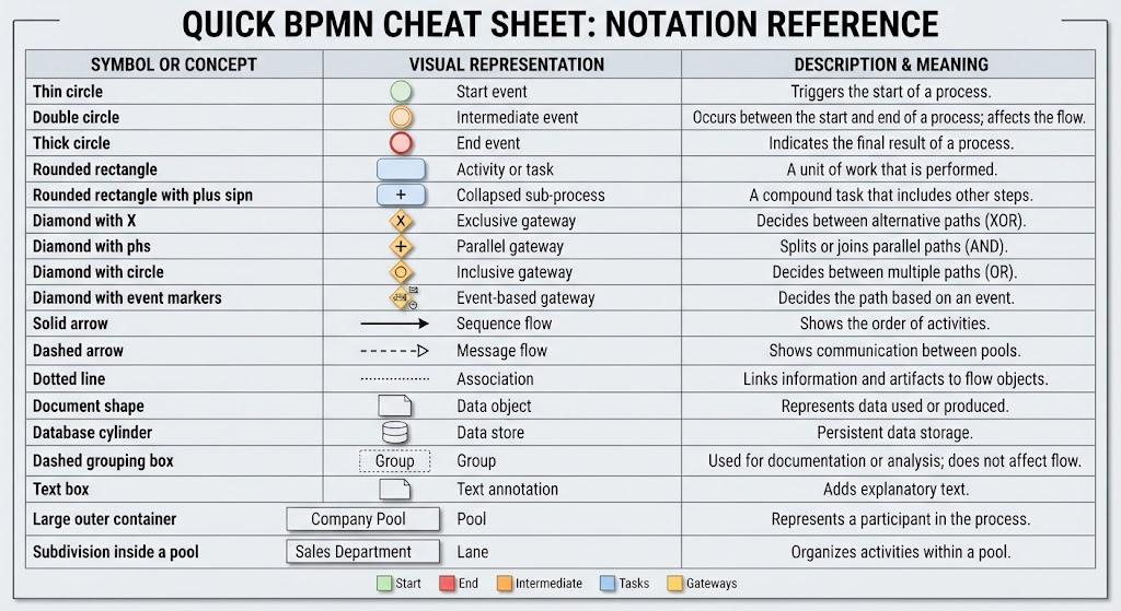
| Symbol or concept | Meaning |
|---|---|
| Thin circle | Start event |
| Double circle | Intermediate event |
| Thick circle | End event |
| Rounded rectangle | Activity or task |
| Rounded rectangle with plus sign | Collapsed sub-process |
| Diamond with X | Exclusive gateway |
| Diamond with plus sign | Parallel gateway |
| Diamond with circle | Inclusive gateway |
| Diamond with event markers | Event-based gateway |
| Solid arrow | Sequence flow |
| Dashed arrow | Message flow |
| Dotted line | Association |
| Document shape | Data object |
| Database cylinder | Data store |
| Dashed grouping box | Group |
| Text box | Text annotation |
| Large outer container | Pool |
| Subdivision inside a pool | Lane |
17. A Simple BPMN Modeling Checklist
Before finalizing a diagram, ask:
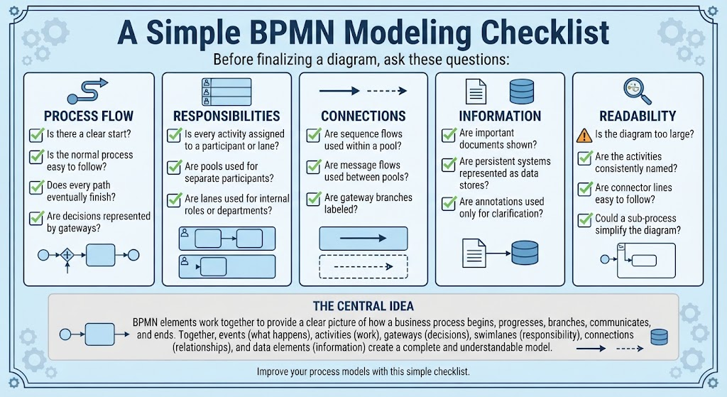
Process flow
-
Is there a clear start?
-
Is the normal process easy to follow?
-
Does every path eventually finish?
-
Are decisions represented by gateways?
Responsibilities
-
Is every activity assigned to a participant or lane?
-
Are pools used for separate participants?
-
Are lanes used for internal roles or departments?
Connections
-
Are sequence flows used within a pool?
-
Are message flows used between pools?
-
Are gateway branches labeled?
Information
-
Are important documents shown?
-
Are persistent systems represented as data stores?
-
Are annotations used only for clarification?
Readability
-
Is the diagram too large?
-
Are the activities consistently named?
-
Are connector lines easy to follow?
-
Could a sub-process simplify the diagram?
The central idea is simple: events describe what happens, activities describe the work, gateways control decisions or parallel paths, swimlanes show responsibility, connections show relationships, and data elements show information. Together, these elements provide a clear picture of how a business process begins, progresses, branches, communicates, and ends.
References
- Comprehensive Guide to BPMN, Visual Paradigm Tooling, AI, and Ecosystem: Official blog post outlining the four pillars of the VP AI ecosystem with practical BPMN examples like Employee Onboarding and Order Fulfillment .
- Mastering Business Process Modeling: A Complete Guide to BPMN and AI-Powered Diagram Generation: Official guide detailing how to use the AI Business Process Diagram generator, with step-by-step instructions and feature comparisons .
- From Text to Process Flow: My Hands-On Review of Visual Paradigm’s AI-Powered BPMN Generator: Independent review testing the generator across real-world scenarios (e-commerce, IT support, banking) from a business analyst perspective .
- AI BPMN Diagram Generator: Professional BPD Tool: Official product page explaining the text-to-diagram feature, how to access it in VP Desktop, and key benefits like standard compliance .
- BPMN、Visual Paradigm 工具、人工智能与生态系统全面指南: Chinese version of the comprehensive guide, covering BPMN fundamentals and AI-driven generation case studies .
- From Text to Process Flow: A Hands-On Review of Visual Paradigm’s AI-Powered BPMN Generator: Detailed case study on a hardware retailer’s shipment process, demonstrating how AI handles gateways, parallel execution, and swimlane logic .
- AI BPMN图生成器:专业BPD工具: Chinese product guide detailing the AI generator’s capabilities, including automatic pool and lane inclusion for cross-functional clarity .
- 我的亲身体验:利用 Visual Paradigm 的 AI 驱动 BPMN 改变工作流程文档: First-hand review of the AI generator’s performance on employee onboarding, customer support, and loan approval scenarios .
- BPMN 2.0 商业流程建模新手实战指南:运用 Visual Paradigm 与 AI 轻松打造专业流程图: Practical tutorial with prompt writing strategies and advanced optimization techniques using the AI Chatbot for conversational refinement .
- BPMN 完整实战教程:Visual Paradigm 体验、AI 功能与生态系统深度指南: Series of articles covering the AI-powered BPMN generator launch, with deep dives into ecosystem integration and practical examples .
This post is also available in Deutsch, Español, فارسی, Français, English, Bahasa Indonesia, 日本語, Polski, Portuguese, Ру́сский, Việt Nam, 简体中文 and 繁體中文.