


Introduction
If you’ve ever struggled to communicate how multiple interaction scenarios fit together within a larger system workflow, you’re not alone. Many product managers, systems architects, and software engineers find themselves jumping between sequence diagrams, activity flows, and use case descriptions—only to lose the big picture in the process.
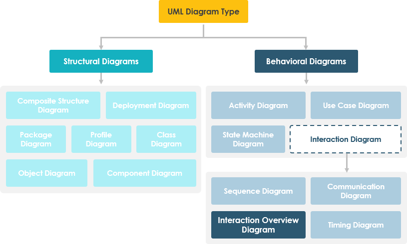
That’s where the Interaction Overview Diagram comes in. As one of the fourteen UML diagram types, it offers a unique “zoomed-out” perspective that bridges high-level control flow with detailed interaction sequences. In this practitioner-focused guide, we’ll walk through what makes this diagram valuable, how to create one effectively using Visual Paradigm, and share real-world insights on when—and when not—to use it. Whether you’re documenting a complex microservices architecture or aligning stakeholders on a multi-step user journey, this guide aims to help you leverage interaction overview diagrams with confidence.

What Is an Interaction Overview Diagram? (And Why Should You Care?)
From a practitioner’s perspective, the Interaction Overview Diagram is like the “table of contents” for your system’s behavioral models. Rather than diving into message-level details, it provides a high-level abstraction—similar to an activity diagram—but with a crucial twist: its nodes can reference other interaction diagrams like sequence diagrams, communication diagrams, or timing diagrams.
Key characteristics users appreciate:
-
Navigability: Link “real” detailed diagrams together for seamless exploration
-
Control Flow Clarity: Model normal, alternative, or conditional flows between interactions
-
Hybrid Notation: Combines familiar elements from both activity and sequence diagrams
-
Scalability: Keep complex systems understandable by separating concerns across diagram layers
💡 Pro Tip from the Field: Start with an interaction overview when onboarding new team members. It gives them a mental map before they dive into the granular sequence diagrams.
Getting Started: Creating Your First Interaction Overview Diagram in Visual Paradigm
Based on hands-on experience with Visual Paradigm, here’s a streamlined workflow that balances efficiency with best practices.
Step 1: Initialize the Diagram
-
Navigate to Diagram > New from the application toolbar
-
In the New Diagram window, select Interaction Overview Diagram
-
Click Next
-
Enter a meaningful diagram name and description. Use the Location field to organize it within your model repository
-
Click OK
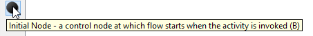
Step 2: Add an Initial Node
The initial node marks the entry point of your control flow.
-
Click Initial Node on the diagram toolbar
-
Click on the canvas to place it
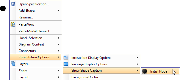
User Note: Captions are hidden by default. To display them: right-click the diagram → Presentation Options → Show Shape Caption → Initial Node
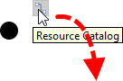
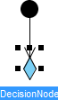
Step 3: Model Decision Points with Decision Nodes
Real-world workflows rarely follow a single path. Here’s how to add branching logic:
-
Hover over the source node (e.g., your initial node)
-
Press and drag the Resource Catalog button outward
-
Release where you want the decision node
-
Select Control Flow -> Decision Node from the catalog
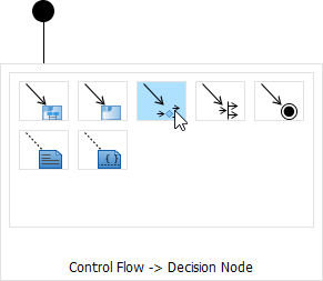
-
Name your decision node (e.g., “Payment Valid?”) and press Enter
Step 4: Embed Interaction Uses (The Power Move)
This is where interaction overview diagrams truly shine—referencing detailed sequence diagrams as reusable components.
-
Hover over your source shape
-
Drag out the Resource Catalog
-
Release at the target location
-
Select Control Flow -> Interaction Use
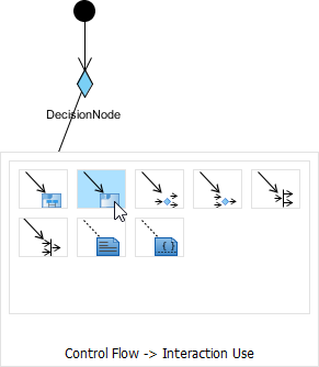
-
Name the interaction use and confirm
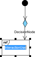
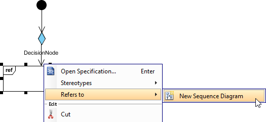
🔗 Linking to Actual Sequence Diagrams
To maximize navigability:
-
Right-click the interaction use shape
-
Select Refers to → New Sequence Diagram
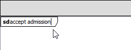
-
Rename the newly created sequence diagram for clarity
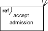
-
Return to your overview: the interaction use caption now displays its referenced diagram
💡 Field Insight: Use consistent naming conventions for interaction uses (e.g., “IU_LoginFlow”) to make cross-diagram navigation intuitive during code reviews or stakeholder walkthroughs.
Practical Tips from Real-World Usage
After working with interaction overview diagrams across multiple projects, here are lessons worth sharing:
✅ Do:
-
Start simple: Model 3–5 key interaction flows before expanding
-
Use descriptive names for interaction uses—they become navigation anchors
-
Color-code decision branches for faster visual parsing in presentations
-
Keep the overview at a “managerial” abstraction level; save message details for referenced diagrams
❌ Avoid:
-
Overloading the overview with too many nodes (aim for <15 for readability)
-
Creating circular references between diagrams
-
Using interaction overviews for purely linear workflows (a simple activity diagram may suffice)
🔧 Tool-Specific Hack: In Visual Paradigm, use the “Model Explorer” pane to quickly jump between an interaction use and its referenced sequence diagram—saving significant context-switching time.
Conclusion: When to Reach for an Interaction Overview Diagram
Interaction Overview Diagrams aren’t a silver bullet—but when used intentionally, they’re incredibly powerful. Consider adopting them when:
-
You’re modeling systems with multiple conditional interaction paths (e.g., e-commerce checkout with payment failures, inventory checks, and user authentication branches)
-
Your team maintains a library of sequence diagrams and needs a “map” to navigate them
-
Stakeholders request a high-level behavioral view without drowning in technical detail
-
You’re documenting compliance workflows where audit trails require clear control flow visualization
Like any modeling technique, its value emerges from disciplined application. Start small, iterate with feedback, and let the diagram evolve alongside your system. When done well, an interaction overview doesn’t just document your architecture—it becomes a living artifact that accelerates onboarding, clarifies requirements, and aligns cross-functional teams.
Ready to try it? Open Visual Paradigm, sketch your first flow, and experience how connecting the dots between interactions can transform how you communicate system behavior.
- References
- What is Interaction Overview Diagram?: Comprehensive explanation of interaction overview diagrams in UML, including their purpose, notation, and relationship to other diagram types.
- What is UML?: Foundational overview of the Unified Modeling Language, its history, purpose, and the fourteen diagram types it encompasses.
- What is Activity Diagram?: Detailed guide to activity diagrams, which share structural similarities with interaction overview diagrams and serve as a basis for understanding control flow modeling.
- What is Sequence Diagram?: Explanation of sequence diagrams, which are commonly referenced within interaction overview diagrams as interaction uses.
- How to draw a Interaction Overview Diagram in UML: Step-by-step tutorial for creating interaction overview diagrams using Visual Paradigm, including practical tips for linking diagrams and managing references.
This post is also available in Deutsch, Español, فارسی, Français, English, Bahasa Indonesia, 日本語, Polski, Portuguese, Ру́сский, Việt Nam, 简体中文 and 繁體中文.