


Introduction: Why Activity Diagrams Matter in Modern System Design
As someone who regularly bridges technical teams and business stakeholders, I’ve found that few tools communicate complex workflows as effectively as UML Activity Diagrams. Whether you’re mapping a multi-step approval process, documenting a user journey, or designing concurrent system operations, activity diagrams provide the visual clarity that text-based specifications often lack.

Recently, I spent time exploring Visual Paradigm’s comprehensive activity diagram capabilities—from basic flowcharting to advanced animation and AI-powered generation. What follows is my practical, experience-based guide to getting the most out of this powerful modeling tool. If you’re evaluating diagramming solutions or looking to level up your UML skills, this review covers everything you need to know.
What Is an Activity Diagram?
Activity diagram is another important diagram in UML to describe the dynamic aspects of the system. Activity diagram is basically a flowchart to represent the flow from one activity to another activity which is a graphical representations of workflows of stepwise activities and actions with support for choice, iteration and concurrency. Typically, activity diagrams primarily show the overall flow of control, they can also include elements showing the flow of data between activities through one or more data stores. Thus, an activity can be described as an operation of the system. The control flow is drawn from one operation to another.
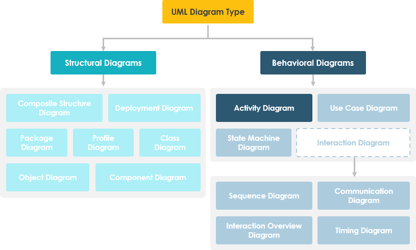
From my experience, the real power of activity diagrams lies in their ability to model both sequential and parallel processes while maintaining readability. Unlike simple flowcharts, they support swimlanes for role-based partitioning, object flows for data tracking, and decision nodes for complex branching logic.
When to Use Activity Diagrams: Practical Scenarios
Activity Diagrams describe how activities are coordinated to provide a service which can be at different levels of abstraction. Typically, an event needs to be achieved by some operations, particularly where the operation is intended to achieve a number of different things that require coordination, or how the events in a single use case relate to one another, in particular, use cases where activities may overlap and require coordination. It is also suitable for modeling how a collection of use cases coordinate to represent business workflows.
Here are the scenarios where I’ve found activity diagrams most valuable:
-
Identify candidate use cases, through the examination of business workflows
-
Identify pre- and post-conditions (the context) for use cases
-
Model workflows between/within use cases
-
Model complex workflows in operations on objects
-
Model in detail complex activities in a high level activity Diagram
In my work, I typically start with activity diagrams during the discovery phase of a project. They help stakeholders visualize “how things actually work” before we commit to technical implementation details.
Getting Started: Creating Your First Activity Diagram
Creating an Activity Diagram
Perform the steps below to create a UML activity diagram in Visual Paradigm:
-
Select Diagram > New from the application toolbar.
-
In the New Diagram window, select Activity Diagram.
-
Click Next.
-
Enter the diagram name and description. The Location field enables you to select a model to store the diagram.
-
Click OK.
The onboarding experience here is refreshingly straightforward. Even if you’re new to UML, the guided workflow gets you from zero to a functional diagram in under a minute.
Creating Swimlanes
You can click either Horizontal Swimlane or Vertical Swimlane on the diagram toolbar.
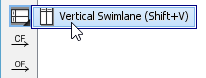
Click on the diagram to create the swimlane.
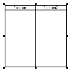
Double-click the partition name to rename it.
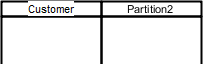
Pro tip from my workflow: I always start by defining swimlanes for each major actor or system component. This immediately clarifies responsibility boundaries and prevents the “who does what?” confusion that plagues many requirements documents.
Inserting Partitions to Swimlanes
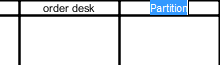
To insert partition to swimlane, right-click on a partition and select either Insert Partition Before or Insert Partition After from the pop-up menu.
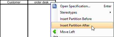
A partition is inserted.
Creating Initial Node and Actions
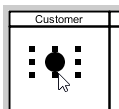
Click Initial Node on the diagram toolbar.
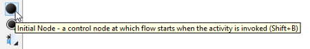
Click inside the partition to create the initial node there.
Creating actions is where the Resource Catalog really shines:
-
Move your mouse pointer over the source shape.
-
Press on the Resource Catalog button and drag it out.
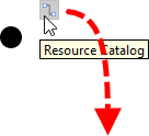
-
Release the mouse button at the place where you want the action to be created.
-
Select Control Flow -> Action from Resource Catalog.
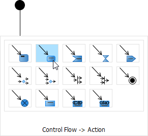
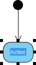
-
A new action will be created and is connected to the source shape with a control flow. Enter its name and press Enter to confirm editing.
The contextual suggestions from the Resource Catalog significantly speed up diagram creation. Instead of hunting through menus, the tool anticipates what you might want to add next—a small but meaningful productivity boost.
Working with Scenarios: From Diagrams to Executable Flows
A scenario is a diagram formed by the internal interaction of a sequence of action, modeled by their sub-diagrams. With scenario, you can produce a diagram which presents an overview of an execution path in activity diagram, so as to know how user and system communicate with each other in order to complete the flow.
Producing Scenario from Activity Diagram
-
Right click on the activity diagram that contains the flows that you want to produce a scenario and select Scenarios > Edit Scenarios… from the popup menu.
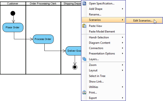
-
In the Edit Scenarios window, click Add… button at the bottom left corner.
-
Select a path for generating scenario. Click OK to confirm.
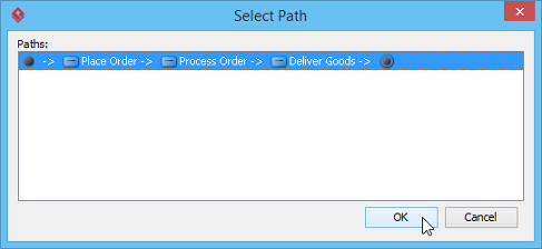
Note: A path is a continuous flow of actions in the diagram, with an initial node placed at the beginning of the actions. Multiple paths are obtained by determining the existence of decision nodes within the flow. -
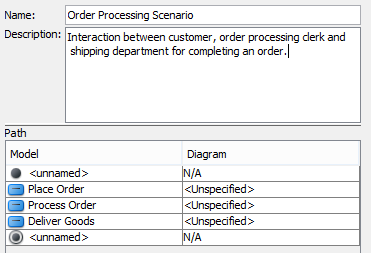
Name the scenario. Add description if necessary.
-
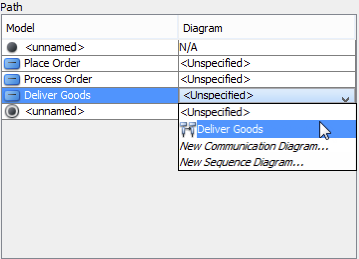
The actions being involved in the flow are listed in the Path table. For actions that have sub-diagram(s), pick up the sub-diagram in Diagram column or just create a new one. You may, however, leave it unspecified which cause that action to be ignored when producing scenario.
-
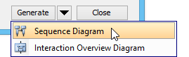
Click on the arrow beside the Generate button and select the type of diagram of the scenario.
Updating Scenario
Whenever the sub-diagram(s) of action(s) are updated, you can update the scenario to make it represents the latest information of interaction. To update scenario, right click on the activity diagram that have scenario produced before, select Scenarios, then the name of scenario from the popup menu.
My take: The scenario feature is particularly valuable for agile teams. Being able to extract and document specific execution paths from a complex diagram helps create focused test cases and user stories without losing the bigger picture.
Splitting Control Flows: Editing Without Starting Over
When you found a control flow in a UML Activity Diagram missing an action and you want to add the action back into the flow, you can make use of the split feature to easily insert the action shape back to a control flow. The insertion of action shape will result in the creation of new flow that connects the new action shape and the “to-shape” that is originally connected by the original flow. The original flow will be updated to connect to the new shape. In other words, the details specified to the original flow, if any, will remain intact.
To use the split resource:
-
Move your mouse pointer over the control flow to which you want to add the action shape.
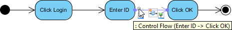
-
Click on
 .
. -
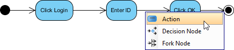
Select Action in the popup menu. You may also add a decision node and fork node into the flow.
-
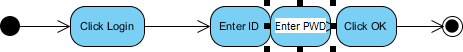
Enter the name of the action and press Enter to confirm.
-
Tidy up the flow.

This split feature has saved me countless hours during iterative design sessions. Instead of deleting and reconnecting multiple elements, I can simply insert a missing step directly into an existing flow—preserving all the metadata and connections I’ve already configured.
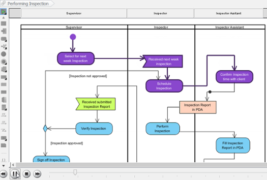
Animating Activity Diagrams: Bringing Your Workflows to Life
The UML tool of Visual Paradigm supports animating activity diagrams. The animation lets you see clearly the flow of actions in a control flow.
-
Select Modeling > Animation from the toolbar.
-
In Activity Diagram Animation window, select a path and then click Play.
Note: Animation can also be started by using any of the ways below:-
Right-click on the diagram background and select Utilities > Animation… from the popup menu.
-
Click the drop-down menu of Modeling Tools and select Animation… on the toolbar.
-
Overview of Animation
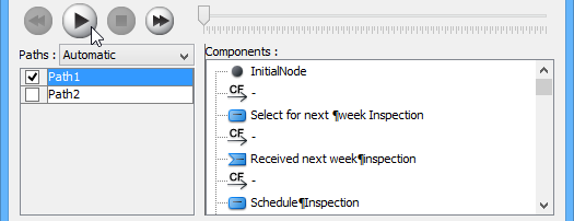
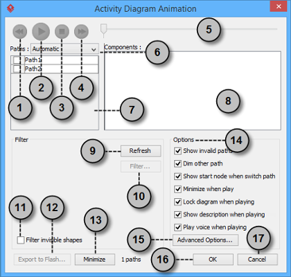
The Activity Diagram Animation window will pop out after clicking Animation…. This window is where you can select an execution path to play an animation.
| No. | Name | Description |
|---|---|---|
| 1 | Backward | Move one shape backward in the flow. |
| 2 | Play | Play or continue to play the animation with Animation minimized. |
| 3 | Stop | Terminate the animation. |
| 4 | Forward | Advance to the next shape in the flow. |
| 5 | Slider | It is used for controlling the flow of animation. |
| 6 | Paths | It provides two ways of producing animation for the possible paths.
Automatic: It is chosen by default. This helps you to detect all possible paths automatically. |
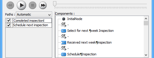
| 7 | Paths list | It lists all possible ways of executing an Activity. By default, paths are named as Path1, Path2, and so forth. You can rename them by double clicking on them and giving meaningful names. |
| 8 | Components list | It displays all components of the selected path. Pressing on a component will highlight the first shape of the chosen path until the chosen shape in the diagram. |
| 9 | Refresh | It is used for re-identifying the paths base on filter assignment and diagram content. |
| 10 | Filter… | It helps removing the non-selected paths by specifying the end result of fork nodes. |
| 11 | Filter invisible shapes | A shape can be set invisible on a diagram, or become invisible due to belonging to an invisible layer. By checking this option, invisible shapes will be ignored when calculating paths. By unchecking, invisible path will be included when calculating paths. By unchecking, you will see a black ball fly on diagram without attaching to the invisible shape(s) when executing a path. |
| 12 | Export to Flash… | Select an output path for exporting this diagram’s animation to Adobe Flash. |
| 13 | Minimize | Click to minimize this window. |
| 14 | Options pane | The Options pane helps you to configure animation.
Show invalid paths: It lists not only the valid and selected path, but also the invalid and non-playable paths in the Paths list. |
| 15 | Advanced Options… | It provides the color and speed options for animation. |
| 16 | OK | Click this button to confirm the settings and close Animation. |
| 17 | Cancel | Click this button to close Animation without saving the editing. |
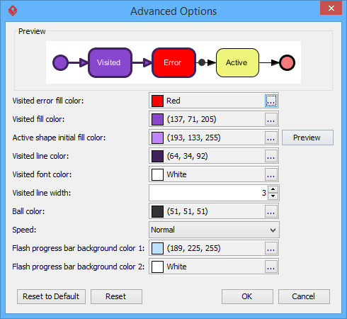
Advanced Options
| Name | Description |
|---|---|
| Visited error fill color | The background color of visited shape that cause an error. An error means the flow object that causes a path invalid. |
| Visited fill color | The background color of visited shapes. |
| Active shape initial fill color | When playing an animation, a tiny black ball will traverse the chosen path, from one shape to another. When it reaches a shape, the shape will render with a transition effect that means transiting from an initial color to visited fill color. This option manages the initial background color for visiting shape. |
| Visited line color | The line color of visited shapes. |
| Visited font color | The font color of visited shapes. |
| Visited line width | The thickness of visited shape’s border. |
| Ball color | The color of ball that goes through a path during animation for indicating the progress of flow. |
| Speed | The pace of animation. |
| Flash progress bar background color 1 | The background color for the top of progress bar in exported Flash movie. |
| Flash progress bar background color 2 | The background color for the bottom of progress bar in exported Flash movie. |
Naming a Path
The Paths list displays all possible animation paths of your diagram. Each path represents a possible way to go through the diagram. By default, paths are named as Path1, Path2, and so forth. It is recommended to name to the path(s) for better clarification.
-
To rename a path, move the mouse pointer on a path in the list and double click on it.
-
Enter the name of path.
-
Press Enter to confirm editing.
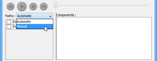
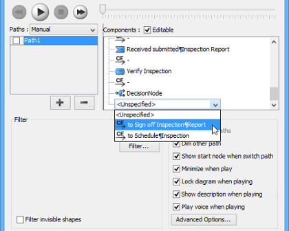
Creating a Manual Path
In Activity Diagram Animation window, all paths are listed in Paths list by default. However, you can manage the flow of animation with your own choice. To create a manual path:
-
Select Manual in Paths.
-
Press Add Path to insert a new path.
-
Select the shapes that are shown on the Components list to direct the flow of animation.
-
Click OK to confirm editing.
Handling Decision
You should choose an outgoing flow when there is more than one option in the flow. Different decisions will lead to different forks and make a different outcome for the flow of animation. Make either decision to view the outcome.
Reviewing an Animation
-
When everything is ready, click Play to start the animation of the selected path.
-
After click Play, Activity Diagram Animation window will be minimized to the bottom of your diagram with several buttons and a slider revealing on it.
Button Name Description 
Backward Move one shape backward in the flow. 
Pause Temporary stop playing the movie. Press Play to continue to play. 
Play Play or continue to play the animation. 
Forward Advance to the next shape in the flow. 
Stop Terminate the animation. 
Maximize Maximize Animation. -
When the animation starts, a black ball will appear at beginning of path and traverse through the path until the end.
-
When the black ball reaches a shape, the shape will turn into purple.
Exporting an Animation
You can export the animation to Web contents so that you can play it externally in another computer just by playing in a Web browser.
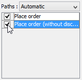
-
From the Paths list in the Animation window, select the execution paths to export as Flash movie.
-
Click the Export to Flash… button at bottom left. This shows the Export to Flash window. Here is a description of the Export to Flash window.
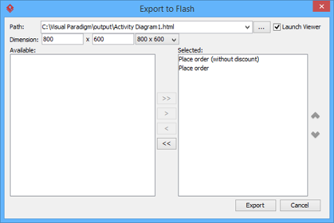
Here is a description of the Export to Flash window.Part Description Path The path of the exported HTML file. Flash movie file (.swf) will also be exported to the same folder as the HTML file. Launch Viewer When checked, default web browser will automatically start and play the exported Flash movie. Dimension The width and height of viewing region of Flash. Available Available paths that can be selected to export to Flash movie for animation. Selected Selected paths to export to Flash movie for animation. -
An HTML web page will be exported. Specify the path of the HTML file. Note that the Flash movie files (.swf) will be exported to the same folder as the HTML file.
-
Choose or enter the dimension of movie if necessary. Note that the dimension determins the size of viewable region instead of the size of diagram.
-
Click Export. Open the HTML file in the web browser to play the movie. If there are more then one path being selected, you can click on the drop down menu at top right corner and select another path to play with.
Personal insight: Animation isn’t just a “nice-to-have”—it’s a powerful validation tool. I’ve used animated diagrams in stakeholder reviews to walk through edge cases and error conditions. Seeing the flow execute step-by-step often reveals logical gaps that static diagrams hide.
Key Features Summary: What Stands Out
Based on my hands-on experience, here are the features that make Visual Paradigm’s activity diagram tool particularly effective:
🔹 AI-Powered Generation: You can instantly generate activity diagrams from text descriptions or use case scenarios using the built-in AI assistant. This dramatically accelerates initial diagram creation.
🔹 Intuitive Editor: The platform features a drag-and-drop interface with a “Resource Catalog” that suggests the next logical element (e.g., connecting an action to a decision node) as you draw.
🔹 Templates & Examples: Access a large library of pre-made templates for various business processes and system behaviors to jumpstart your design.
🔹 Collaboration: Real-time collaborative editing allows teams to work on the same diagram simultaneously in the Visual Paradigm Cloud.
🔹 Animation & Export: The ability to animate workflows and export them as interactive web content transforms static documentation into engaging, executable specifications.
Access Options: Choosing the Right Tier
-
Visual Paradigm Online (Free): A web-based free edition specifically for non-commercial and personal use. Great for learning and small projects.
-
Visual Paradigm Desktop: A more powerful version for professional modeling, supporting advanced features like AI generation and team collaboration. Ideal for enterprise teams and complex system design.
Conclusion: Is Visual Paradigm Right for Your Workflow Modeling Needs?
After extensively testing Visual Paradigm’s activity diagram capabilities, I can confidently say this tool strikes an exceptional balance between power and usability. For product managers, business analysts, and systems architects who need to communicate complex workflows clearly, it delivers tangible value.
Who should use it:
-
Teams practicing agile or iterative development who need living documentation
-
Business analysts mapping cross-functional processes
-
Technical leads designing concurrent or distributed systems
-
Educators teaching UML or workflow modeling concepts
Consider alternatives if:
-
You only need very simple flowcharts (a lighter tool may suffice)
-
Your organization has strict constraints on cloud-based collaboration tools
-
You’re working exclusively with legacy UML tools that must integrate
My final recommendation: Start with the free Online edition to evaluate the core experience. If you find yourself creating multiple diagrams or collaborating with teammates, the Desktop version’s advanced features—particularly AI generation, animation, and scenario management—justify the investment.
Activity diagrams are more than just pretty pictures; they’re executable specifications that bridge the gap between requirements and implementation. With Visual Paradigm, creating and maintaining those diagrams becomes not just feasible, but genuinely enjoyable.
References
- What is Activity Diagram?: Comprehensive introduction to UML activity diagrams, their purpose, and core components within the UML diagram hierarchy.
- What is UML?: Foundational overview of the Unified Modeling Language, its history, and its role in software engineering.
- Why UML Modeling?: Explores the practical benefits and business value of adopting UML for system design and documentation.
- Overview of the 14 UML Diagram Types: Comparative guide to all standard UML diagram types and their appropriate use cases.
- How to draw a Activity Diagram in UML: Step-by-step tutorial for creating activity diagrams using Visual Paradigm’s interface and tooling.
- Splitting a control flow in Activity Diagram: Practical guide to editing existing control flows by inserting new actions without breaking connections.
- How to animate an Activity Diagram: Detailed instructions for using animation features to visualize and validate workflow execution paths.
- Activity Diagram: Software design handbook entry covering activity diagram best practices and modeling patterns.
- How to Draw Activity Diagram?: Official user guide documentation for activity diagram creation workflows.
- Activity Diagram (PDF): Downloadable PDF version of the activity diagram handbook for offline reference.
- AI Activity Diagram Generation: Release notes and feature overview for AI-powered diagram generation capabilities.
- YouTube Tutorial: Activity Diagram Basics: Video walkthrough demonstrating fundamental activity diagram creation techniques.
- YouTube Tutorial: Advanced Activity Diagram Features: Advanced video tutorial covering swimlanes, concurrency, and scenario modeling.
- Visual Paradigm Online: Free Activity Diagram Tool: Web-based free tier offering for non-commercial activity diagram creation.
- Visual Paradigm Online: Free Activity Diagram Software: Alternative landing page for the free online diagramming platform.
- Team Collaboration Toolset: Overview of real-time collaboration features for distributed modeling teams.
- Chat Visual Paradigm: AI-Generated Design Export: Guide to exporting AI-generated diagrams to the desktop application for advanced editing.
- Activity Diagram Tutorial (Online): Interactive web tutorial for learning activity diagram fundamentals.
- Beginner’s Guide to Activity Diagrams: Blog post tailored for newcomers to UML and workflow modeling.
- Activity Diagram Software Features: Feature comparison and capabilities overview for the online activity diagram tool.
- Use Case Elaboration with Activity Diagrams: Practical guide to using activity diagrams for refining and detailing use case specifications.
This post is also available in Deutsch, Español, فارسی, Français, English, Bahasa Indonesia, 日本語, Polski, Portuguese, Ру́сский, Việt Nam, 简体中文 and 繁體中文.