


Introduction to Sequence Diagrams
Both sequence diagrams and collaboration diagrams are kinds of interaction diagrams. Interaction diagrams address the dynamic view of a system. A sequence diagram is an interaction diagram that emphasizes the time-ordering of messages. It depicts the objects and classes involved in the scenario and the sequence of messages exchanged between the objects needed to carry out the functionality of the scenario.
💡 Typical Usage: Use one sequence diagram to specify a use case’s main flow, and variations of that diagram to specify a use case’s exceptional flows.
Core Elements of Sequence Diagrams
🧱 Object
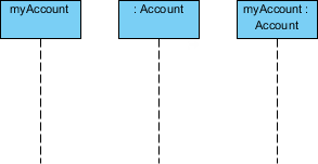
In UML, an object in a sequence diagram is drawn as a rectangle containing the name of the object, underlined. An object can be named in one of three ways:
| Naming Style | Example | Description |
|---|---|---|
| Object name only | myAccount |
Specific instance reference |
| Object name + class | myAccount :Account |
Instance with explicit type |
| Class name only (anonymous) | :Account |
Represents any object of the class |
⏳ Lifeline
Entities or participants in a collaboration (scenario) are written horizontally across the top of the diagram. A lifeline is represented by a dashed vertical line drawn below each object, indicating the existence of the object over time.
🔹 Object names can be specific (e.g.,
myAccount) or general (e.g.,myAccount :Account).
🔹 Anonymous objects (:Account) represent any object in the class.
🔹 Each object has its timeline represented by a dashed line below the object.
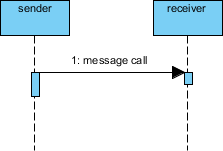
🔹 Messages between objects are represented by arrows pointing from sender to receiver.
Everything in an object-oriented system is accomplished by objects. Objects take on responsibilities like:
-
Managing data
-
Moving data around in the system
-
Responding to inquiries
-
Protecting the system
Objects work together by communicating or interacting with one another.
📨 Messages
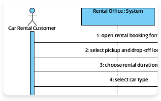
Messages depict the invocation of operations and are shown horizontally, drawn from the sender to the receiver. Ordering is indicated by vertical position, with the first message shown at the top of the diagram, and the last message shown at the bottom. As a result, sequence numbers are optional.
Message Types
1. Synchronous Message
A synchronous message (typically an operation call) is shown as a solid line with a filled arrowhead. It is a regular message call used for normal communication between sender and receiver.
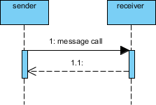
2. Return Message
A return message uses a dashed line with an open arrowhead.
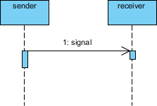
3. Asynchronous Message
An asynchronous message has a solid line with an open arrowhead. A signal is an asynchronous message that has no reply.
🔄 Creation and Destruction Messages
Participants do not necessarily live for the entire duration of a sequence diagram’s interaction. Participants can be created and destroyed according to the messages that are being passed.
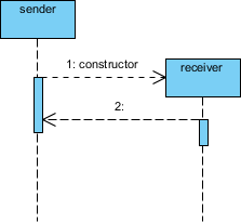
Constructor Message
A constructor message creates its receiver. Senders that already exist at the start of the interaction are placed at the top of the diagram. Targets that are created during the interaction by a constructor call are automatically placed further down the diagram.
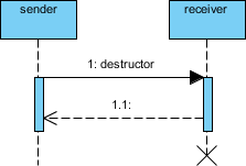
Destructor Message
A destructor message destroys its receiver. There are other ways to indicate that a target is destroyed during an interaction. Only when a target’s destruction is set to ‘after destructor’ do you have to use a destructor.
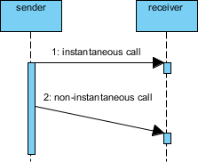
⏱️ Non-Instantaneous Messages
Messages are often considered to be instantaneous—the time it takes to arrive at the receiver is negligible. These messages are drawn as horizontal arrows.
To indicate that it takes a certain while before the receiver actually receives a message, a slanted arrow is used.
🎯 Focus of Control
Focus of Control represents the period during which an element is performing an operation. The top and bottom of the rectangle are aligned with the initiation and completion time respectively.
┌─────────────────┐
│   Activation    │ ← Object is actively processing
└─────────────────┘
🔁 Iteration Notation
Iteration notation represents a message sent many times to multiple receiver objects, as would happen when iterating over a collection. You can show the basis of the iteration within brackets:
*[for all order lines]
*[i = 1 to n]
*[while condition]
📋 Example: Place Order
The example shows a Sequence diagram with three participating objects: Customer, Order, and Stock. Without even knowing the notation formally, you can probably get a pretty good idea of what is going on.
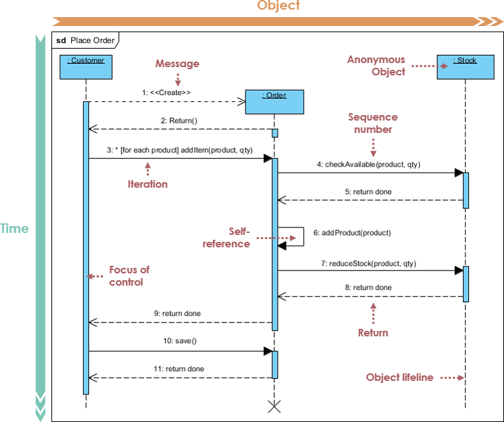
Step-by-Step Flow:
-
Steps 1-2: Customer creates an order
-
Step 3: Customer adds items to the order
-
Steps 4-5: Each item is checked for availability in inventory
-
Steps 6-8: If the product is available, it is added to the order
-
Step 9: Return confirmation
-
Steps 10-11: Save and destroy order
🧩 Sequence Fragments (Combined Fragments)
In a UML sequence diagram, combined fragments let you show loops, branches, and other alternatives. A combined fragment consists of one or more interaction operands, each enclosing one or more messages, interaction uses, or combined fragments.
A sequence fragment is represented as a box called a combined fragment, which encloses a portion of the interactions within a sequence diagram. The fragment operator (in the top left corner) indicates the type of fragment.
Fragment Operators Reference Table
| Operator | Meaning |
|---|---|
alt |
Alternative: Multiple fragments; only the one whose condition is true will execute |
opt |
Optional: The fragment executes only if the supplied condition is true (equivalent to alt with one trace) |
par |
Parallel: Each fragment is run in parallel |
loop |
Loop: The fragment may execute multiple times; the guard indicates the basis of iteration |
critical |
Critical region: The fragment can have only one thread executing it at once |
neg |
Negative: The fragment shows an invalid interaction |
ref |
Reference: Refers to an interaction defined on another diagram. The frame covers the lifelines involved. Parameters and return values can be defined |
sd |
Sequence diagram: Used to surround an entire sequence diagram |
Example: Place Order Scenario with Fragments
A member of a ship who would like to place an order online. The item ordered will be sent to the member either by courier or by ordinary mail depending on the member status (VIP, Ordinary membership). Optionally, the shop will send the member a confirmation notification if the member opted for the notification option in the order.
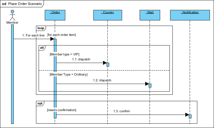
💡 This example demonstrates:
altfragment for VIP vs. Ordinary shipping logic
optfragment for optional confirmation notificationClear separation of conditional flows
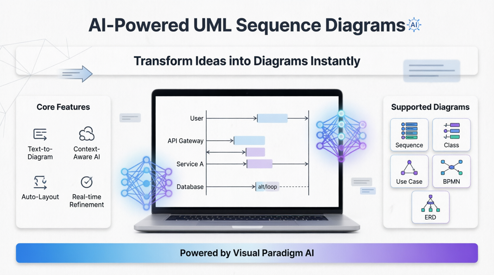
🤖 Smarter Diagrams. Powered by AI.
Describe what you need, and our AI builds it for you — perfectly laid out, beautifully designed, and ready to refine.

✨ Generate Diagrams Instantly from Text
Turn your ideas into diagrams instantly with AI — just type what you need and get accurate, presentation-ready diagrams without templates or manual drawing.

🎨 Always Beautiful, Always Clear
AI generates clean, balanced, and readable diagrams with perfect spacing and alignment, so you can focus on ideas instead of rearranging shapes.
🧠 AI That Understands Context
Our AI interprets your intent, fills in missing details, and suggests relationships to expand your ideas into structured, accurate diagrams.
✏️ Fully Editable & Seamlessly Integrated
Refine and customize diagrams with full control — move shapes, rename elements, and change styles while AI gives you a head start.
🖼️ AI Diagram Examples
Use Case Diagram
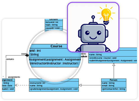
Class Diagram
Sequence Diagram
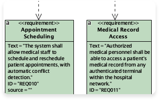
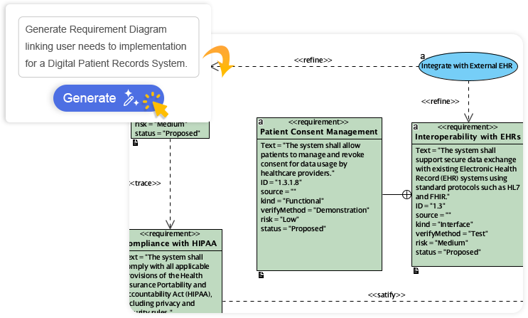
Requirement Diagram
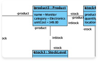
Object Diagram
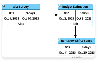
Enhanced PERT Chart
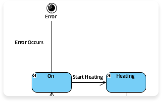
State Diagram
Visual Paradigm‘s AI diagram generator allows you to create professional, standards-compliant diagrams instantly from simple natural language prompts. Instead of manually drawing shapes, you describe your system or workflow, and the AI generates a structured layout that is fully editable within the Visual Paradigm ecosystem.
📚 AI Diagram Generation Guide: Instantly Create System Models
📚 AI Elastic Architecture Diagram Generator
📚 AI Object Diagram Generator
📚 New AI Diagram Generator – Product Updates
📚 AI PERT Chart Generator
🔑 Key Features
-
Instant Text-to-Diagram: Converts plain text (e.g., “A user logs in and selects a product”) into structured visuals like UML, BPMN, and ERDs.
-
Interactive Chatbot: Refine your work using conversational commands like “Add a payment gateway” or “Rename Customer to Buyer” to update the diagram in real-time.
-
Intelligent Analysis: The AI can identify missing actors, suggest relationships (like
<<include>>or<<extend>>), and optimize workflows from 1NF to 3NF for database designs. -
Documentation Generation: Beyond visuals, the tool can produce project summaries, detailed reports, and technical requirements based on your models.
📊 Supported Diagram Types
The AI engine currently supports over 13 diagram types, including:
UML Diagrams
-
Class Diagram
-
Sequence Diagram
-
Use Case Diagram
-
Activity Diagram
-
State Machine Diagram
-
Component Diagram
-
Package Diagram
Business & Strategy
-
BPMN
-
Flowcharts
-
SWOT Analysis
-
PESTLE Analysis
-
ArchiMate
Technical & Engineering
-
Entity Relationship Diagrams (ERD)
-
SysML
-
PERT Charts
🚀 How to Access
💻 Desktop Application
In the Visual Paradigm Desktop application (Professional Edition or higher):
Tools > AI Diagram Generation
🌐 Online Access
-
Use the web-based AI Diagram Generator
-
Or use the AI Chatbot to generate and import diagrams into your workspace
📚 References
-
Visual Paradigm AI Diagram Generation: Create professional diagrams instantly from natural language prompts with AI-powered tools.
-
AI Diagram Generator Release Notes: Product updates and announcements for the AI Diagram Generator feature.
-
Visual Paradigm AI Chatbot: Interactive AI assistant for refining and generating diagrams through conversation.
-
AI Chatbot Feature Page: Learn about conversational AI tools for diagram refinement and creation.
-
Comprehensive Review: Visual Paradigm AI Features: Third-party review of Visual Paradigm’s AI diagram generation capabilities.
-
AI Diagram Generation Tutorial Video: Video walkthrough of creating diagrams using Visual Paradigm’s AI tools.
-
ERD Tool with AI Support: Entity Relationship Diagram tool enhanced with AI-powered features.
-
AI Use Case Diagram Refinement Tool: AI assistant for improving and expanding use case diagrams.
-
AI Diagram Generator Now Supports 13 Diagram Types: Announcement of expanded diagram type support for AI generation.
-
AI Package Diagram Generation: New capability for generating UML package diagrams with AI.
-
Visual Paradigm Platform Overview: Overview of Visual Paradigm’s visual modeling and business analysis capabilities.
-
AI Diagram Generation Demo Video: Demonstration of AI-powered diagram creation workflow.
-
Desktop AI Activity Diagram Generation: Release notes for AI-powered activity diagram generation in desktop application.
-
AI Diagram Generator Tutorial Video: Step-by-step video guide for using the AI diagram generator.
This post is also available in Deutsch, Español, فارسی, Français, English, Bahasa Indonesia, 日本語, Polski, Portuguese, Ру́сский, Việt Nam, 简体中文 and 繁體中文.