
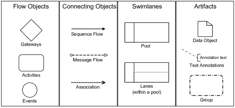
In the realm of business process management, clarity is the currency of efficiency. Business Process Model and Notation (BPMN) 2.0 serves as the universal language for modeling these processes. It allows organizations to visually represent complex workflows in a way that is easily understood by both technical developers and business stakeholders.
This tutorial breaks down the fundamental architecture of a BPMN diagram. By understanding the five core categories of elements—Flow Objects, Connecting Objects, Swimlanes, Artifacts, and Data—users can construct precise models that drive organizational success.
1. The Core: Flow Objects
Flow objects are the primary building blocks of a BPMN diagram. They are the elements that define the behavior and logic of the process. In the BPMN standard, there are three distinct types of flow objects that every modeler must master:
- Events: Represented by circles, events are things that happen during a process. They are the triggers that start the process (Start Events) and the outcomes that end it (End Events). They can also represent intermediate occurrences like message arrivals or timer expirations.
- Activities: Represented by rounded rectangles, activities are the actual work performed. This is the “verb” of the process. A single activity can be as simple as a single task or complex enough to be broken down into a sub-process.
- Gateways: Represented by diamonds, gateways control the divergence and convergence of the process flow. They determine the logic of the path, such as an Exclusive Gateway (XOR) which chooses one path based on a condition, or a Parallel Gateway (AND) which splits the flow to execute multiple paths simultaneously.
2. Connecting the Logic: Connecting Objects
Flow objects do not exist in isolation; they must be linked to form a coherent workflow. Connecting Objects provide the links between the elements, defining the sequence and the nature of the communication.
- Sequence Flow: Represented by a solid line with a classic arrowhead, this connects activities within the same process. It dictates the order in which steps are performed.
- Message Flow: Represented by a dashed line with a hollow circle at the start and an open arrow at the end. This is crucial for communication between different participants or pools, indicating a message being sent from one process to another.
- Associations: Represented by a dashed line, these are used to link flow objects to data objects or annotations, providing context without altering the process flow.
3. Organizing Roles: Swimlanes
To understand who is responsible for what, BPMN utilizes Swimlanes. These are graphical containers that partition the process space. There are two levels of swimlanes:
- Pools: A pool represents a major participant in the process, often a distinct organization or system. A pool can be seen as a container for a single process.
- Lanes: Lanes are subdivisions of a pool. They represent specific roles, departments, or actors within that participant. By organizing activities into lanes, the diagram clarifies exactly which role performs each task.
4. Enriching the Model: Artifacts and Data
While Flow Objects define the behavior and Swimlanes define the roles, Artifacts and Data add the necessary context and information required to execute the process.
Artifacts
Artifacts are elements used to add additional information to a diagram without changing the flow logic. Common artifacts include:
- Data Objects: Represent the data (documents, files) created or consumed by an activity.
- Groups: Visual boundaries (dashed rectangles) used to group elements for documentation purposes, such as categorizing activities by project phase.
- Text Annotations: Used to explain specific parts of the diagram with detailed notes.
Data
Data in BPMN is not just an artifact; it is a critical component of process execution. The standard classifies data into four key kinds:
- Data Objects: General data entities associated with activities.
- Data Inputs: The specific data required to start or perform an activity.
- Data Outputs: The data generated as a result of an activity.
- Data Stores: Represent persistent storage, such as a database or a file system, where information is saved for later retrieval.
Tooling: Visual Paradigm
To effectively translate these concepts into professional diagrams, robust tooling is essential. Visual Paradigm is a comprehensive modeling platform designed to handle the full spectrum of BPMN 2.0 requirements.
Visual Paradigm provides a drag-and-drop interface that strictly adheres to the standard specifications. When using Visual Paradigm for BPMN, users benefit from:
- Strict Conformance: The tool enforces the BPMN 2.0 syntax rules, ensuring that gateways, events, and flows are connected correctly according to the specification.
- Visual Clarity: It allows for the easy creation of complex swimlanes and pools, automatically managing the layout to keep diagrams readable.
- Execution Readiness: Diagrams created in Visual Paradigm can often be executed or converted into code, bridging the gap between design and implementation.
By mastering these elements and utilizing tools like Visual Paradigm, you can create process models that are not just drawings, but powerful blueprints for business improvement.