


Business Process Model and Notation (BPMN) serves as the industry standard for modeling business processes. It provides a graphical notation that is understandable by all business stakeholders, from technical developers to business analysts. Without a shared language, process improvement initiatives often stall due to miscommunication. This guide breaks down the core architecture of BPMN diagrams, focusing on the three pillars that drive process logic: Events, Gateways, and Flows.
Understanding these components allows organizations to map complex workflows accurately. Whether you are documenting a procurement cycle or orchestrating a customer onboarding journey, precision in notation ensures clarity. We will explore the specific symbols, their behaviors, and the rules governing their usage without referencing specific software tools.
1. Events: The Triggers and Outcomes ⏱️
Events represent something that happens during the execution of a process. They are depicted as circles. The thickness of the circle border indicates the type of event. Events do not start or end a process in isolation; they mark a point of action or reaction within the flow.
1.1 The Three Event States
Events are categorized by their position and function within a sequence:
- Start Event: Marks the beginning of a process. It has no incoming sequence flow. There must be at least one start event in every process diagram. If multiple start events exist, the process is triggered by any one of them.
- Intermediate Event: Occurs between the start and end. It represents a pause or an occurrence that happens during the process lifecycle. These events can catch an incoming trigger or throw an outgoing signal.
- End Event: Marks the termination of a process. A process can have multiple end events to indicate different outcomes (success, failure, cancellation).
1.2 Event Types and Their Symbols
The type of event is defined by the icon inside the circle. The border thickness also provides a visual cue: thin for normal events, thick for boundary events attached to activities, and double lines for complex or multi-instance scenarios.
| Event Type | Visual Indicator | Functionality | Common Use Case |
|---|---|---|---|
| Message Event | Envelope Icon | Receives or sends a message between participants. | Waiting for an email reply or sending an invoice. |
| Timer Event | Clock Icon | Triggers based on time or duration. | Reminder sent 3 days after signup. |
| Error Event | Exclamation Icon | Handles system or runtime errors. | Database connection failure during checkout. |
| Signal Event | Lightning Bolt Icon | Broadcasts or catches signals across the process. | Global alert triggering multiple workflows. |
1.3 Boundary Events
Boundary events are a specialized form of intermediate events attached to the side of an activity. They allow for the interruption of an ongoing activity.
- Interrupting Boundary Event: When the event occurs, it cancels the activity it is attached to. For example, if a timer boundary event fires, the task stops immediately.
- Non-Interrupting Boundary Event: When the event occurs, the activity continues running in parallel. This is useful for logging or notification purposes without stopping the core task.
For instance, in a loan approval process, a boundary event might trigger if the applicant submits missing documents. The approval task continues, but a notification is sent to the applicant simultaneously.
2. Gateways: The Decision Points 🚦
Gateways control the divergence and convergence of paths within a process. They are depicted as diamonds. Gateways do not perform work; they direct the flow based on conditions or the presence of tokens.
2.1 Exclusive Gateway (XOR)
The Exclusive Gateway is the most common decision point. It represents a choice where only one path can be taken. It acts as a logical OR.
- Logic: If condition A is true, follow path A. If condition B is true, follow path B. Only one path is active.
- Visual: A diamond with an ‘X’ inside.
- Example: A user submits a form. If the data is valid, proceed to save. If invalid, show an error. Both cannot happen at the same time.
2.2 Parallel Gateway (AND)
The Parallel Gateway splits or merges flows simultaneously. It represents a logical AND. All outgoing paths are activated at the same time, and all incoming paths must complete before the gateway proceeds.
- Logic: If path A and path B are triggered, both run concurrently.
- Visual: A diamond with a plus sign (+) inside.
- Example: After a purchase is confirmed, send an email receipt AND update the inventory system. Both tasks happen at once.
2.3 Inclusive Gateway (OR)
The Inclusive Gateway allows for one or more paths to be taken based on conditions. It is more flexible than the Exclusive Gateway.
- Logic: If condition A is met, take path A. If condition B is met, take path B. If both are met, take both paths.
- Visual: A diamond with an ‘O’ inside.
- Example: A customer qualifies for a discount. They may receive a text message, an email, or both, depending on their preferences.
2.4 Event-Based Gateway
This gateway waits for an event to occur rather than a condition. It is often used in scenarios where multiple outcomes are possible, and the process must react to whichever happens first.
- Logic: The process waits. If Event A happens, go left. If Event B happens, go right. Once one path is taken, the other is cancelled.
- Visual: A diamond with a circle inside.
- Example: Waiting for a customer response. If they reply within 24 hours, proceed to call back. If they do not reply, send a reminder.
3. Flows and Activities: The Work 🔄
While events and gateways control the logic, flows and activities represent the actual work being done. Understanding the distinction between sequence flows and message flows is critical for accurate modeling.
3.1 Sequence Flows
Sequence flows define the order of activities within a single process instance. They are represented by solid arrows.
- Direction: Flow goes from top to bottom, left to right.
- Usage: Connects events, gateways, and activities within the same pool.
- Labeling: Conditions should be labeled on outgoing paths from gateways to clarify the logic.
3.2 Message Flows
Message flows represent the exchange of information between participants (pools). They are represented by dashed arrows with an open circle at the start and an open arrow at the end.
- Direction: Indicates the direction of communication.
- Usage: Connects different pools or lanes. It cannot connect two activities within the same pool.
- Context: Used to show that a process in one department waits for a response from another department.
3.3 Activities and Tasks
Activities are the work performed. They are represented by rounded rectangles.
- User Task: Work performed by a human. Requires manual intervention.
- Service Task: Work performed by an automated system or backend service. No human interaction.
- Script Task: Logic defined by a script or code snippet.
- Send/Receive Task: Sending or receiving messages without waiting for a response (asynchronous).
3.4 Sub-Processes
Complex processes can be broken down into sub-processes to maintain diagram readability.
- Collapsed Sub-Process: Shows the task as a single box with a plus sign. Details are hidden.
- Expanded Sub-Process: Shows the internal logic of the task within the same diagram.
- Call Activity: References a reusable process definition defined elsewhere.
4. Structure and Containers 🧩
Organizing the diagram is as important as the symbols used. BPMN uses containers to group elements logically.
4.1 Pools and Lanes
Pools represent participants in a process. A single pool represents one organization. Multiple pools indicate multiple organizations interacting.
- Pool: The rectangular container for the process.
- Lane: Divides the pool into sub-categories, usually representing roles, departments, or systems.
For example, a “Customer Onboarding” process might have lanes for “Sales,” “IT Support,” and “Finance.” Tasks are placed in the lane responsible for them.
4.2 Data Objects
Data objects represent information created or consumed during the process. They are depicted as pages with a folded corner.
- Usage: Connects to tasks to show input or output.
- Example: A “Contract” document is attached to a “Review Contract” task.
4.3 Text Annotations
Annotations allow writers to add notes or explanations to the diagram without cluttering the flow. They are represented by a document with text lines.
- Usage: Clarify complex rules or provide context for specific tasks.
- Best Practice: Use sparingly to avoid diagram confusion.
5. Best Practices for Readability 📝
A well-constructed BPMN diagram is self-explanatory. Poorly constructed diagrams create confusion and require constant verbal explanation.
- Keep it Linear: Try to keep the flow moving from left to right or top to bottom. Avoid crisscrossing lines.
- Consistent Symbol Usage: Do not mix gateways arbitrarily. If a gateway splits paths, ensure the conditions are clear.
- Limit Complexity: If a diagram becomes too large, use sub-processes or call activities to break it down.
- Clear Labels: Every sequence flow leaving a gateway should have a label (e.g., “Yes,” “No,” “Status: Approved”).
- Balance Gateways: Every split gateway should ideally have a corresponding merge gateway to ensure the process returns to a single flow.
6. Common Pitfalls to Avoid ⚠️
Even experienced modelers can introduce errors. Being aware of common mistakes helps maintain high-quality documentation.
- Dangling Flows: Every element should be connected. An activity with no incoming or outgoing flow is a dead end.
- Orphaned Gateways: A gateway that splits but never merges can lead to multiple end states that are hard to track.
- Complex Logic in Tasks: Do not put complex decision logic inside a task box. Use a gateway to handle the decision.
- Message Flow Confusion: Ensure message flows only cross pool boundaries. Sequence flows should not cross pool boundaries unless they represent a specific integration.
7. The Impact of Accurate Modeling 📊
Investing time in accurate BPMN modeling yields tangible results. It reduces ambiguity in development teams and aligns business expectations.
- Efficiency: Identifying bottlenecks becomes easier when the flow is visualized correctly.
- Compliance: Regulatory requirements can be mapped directly to specific tasks and gateways.
- Automation: Clear logic paths allow automation tools to execute processes without human intervention.
- Communication: Stakeholders can review the diagram and understand the process without needing a presentation.
8. Summary of Components 🏁
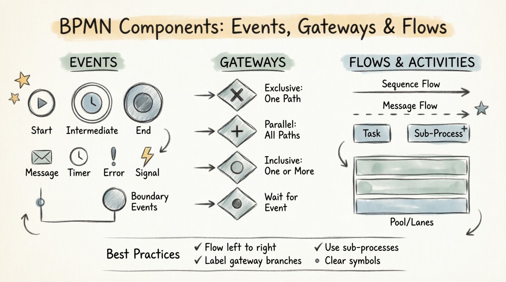
To recap, the core of BPMN relies on the interaction of specific elements:
- Events: Start, Intermediate, End. They trigger and conclude actions.
- Gateways: Exclusive, Parallel, Inclusive, Event-Based. They control branching and merging.
- Flows: Sequence and Message. They define the path and interaction.
- Activities: Tasks, Sub-processes. They represent the work.
- Containers: Pools and Lanes. They organize the scope.
Mastering these components requires practice. Start with simple linear flows, then introduce gateways for decision making, and finally add events for external triggers. As the complexity grows, the discipline of using standard notation ensures the model remains valid and useful for the organization.
By adhering to these standards, teams build a robust foundation for process improvement. The notation is a tool for clarity, not just documentation. When every stakeholder understands the diagram, the path to optimization becomes clear.
This post is also available in Deutsch, Español, فارسی, Français, English, Bahasa Indonesia, 日本語, Polski, Portuguese, Ру́сский, Việt Nam, 简体中文 and 繁體中文.