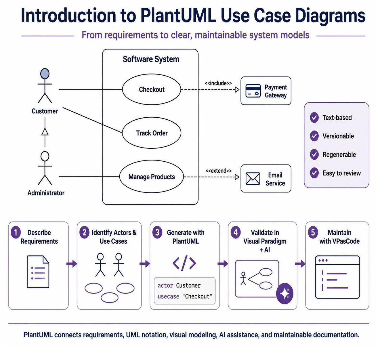
A use case diagram is a UML behavioral diagram that shows how external users or systems interact with a system. It focuses on what the system does from an actor’s perspective, not on internal implementation details.
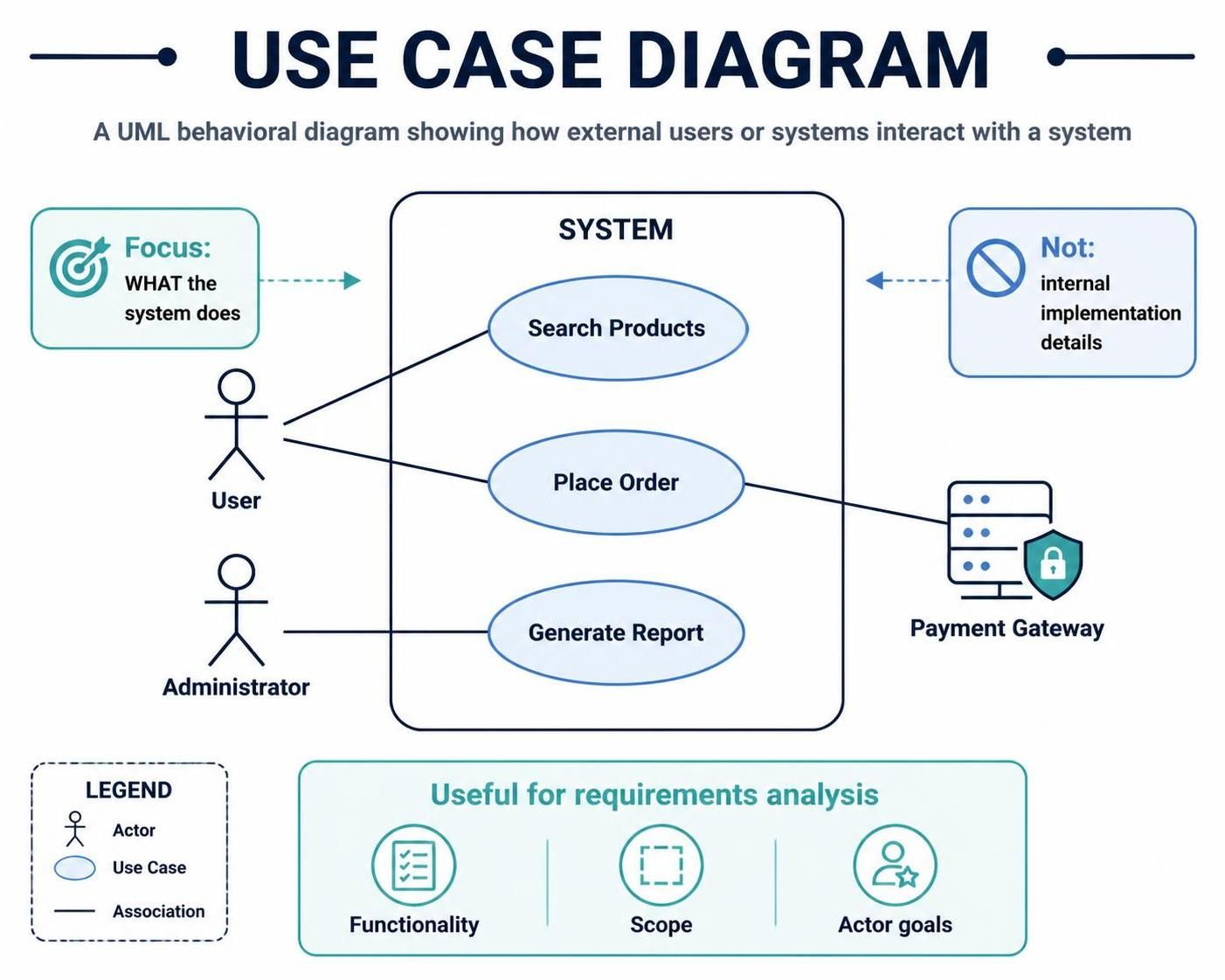
Use case diagrams are especially useful during requirements analysis because they provide a high-level view of system functionality and scope.
1. What a Use Case Diagram Shows
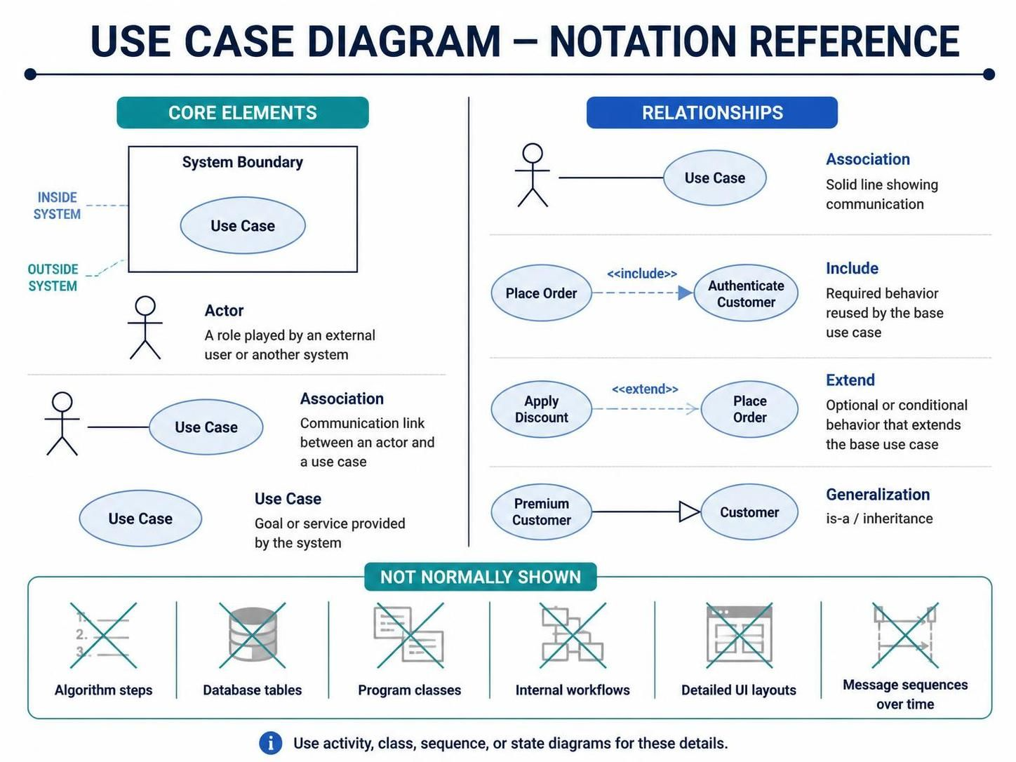
A use case diagram typically contains:
-
System boundary — defines what is inside the system being modeled.
-
Actors — external users, organizations, devices, or systems that interact with it.
-
Use cases — goals or services the system provides.
-
Associations — communication links between actors and use cases.
-
Relationships between use cases — such as
<<include>>and<<extend>>. -
Generalization — inheritance between actors or use cases.
A use case diagram does not normally show:
-
Algorithm steps
-
Database tables
-
Program classes
-
Internal workflows
-
Detailed user-interface layouts
-
Message sequences over time
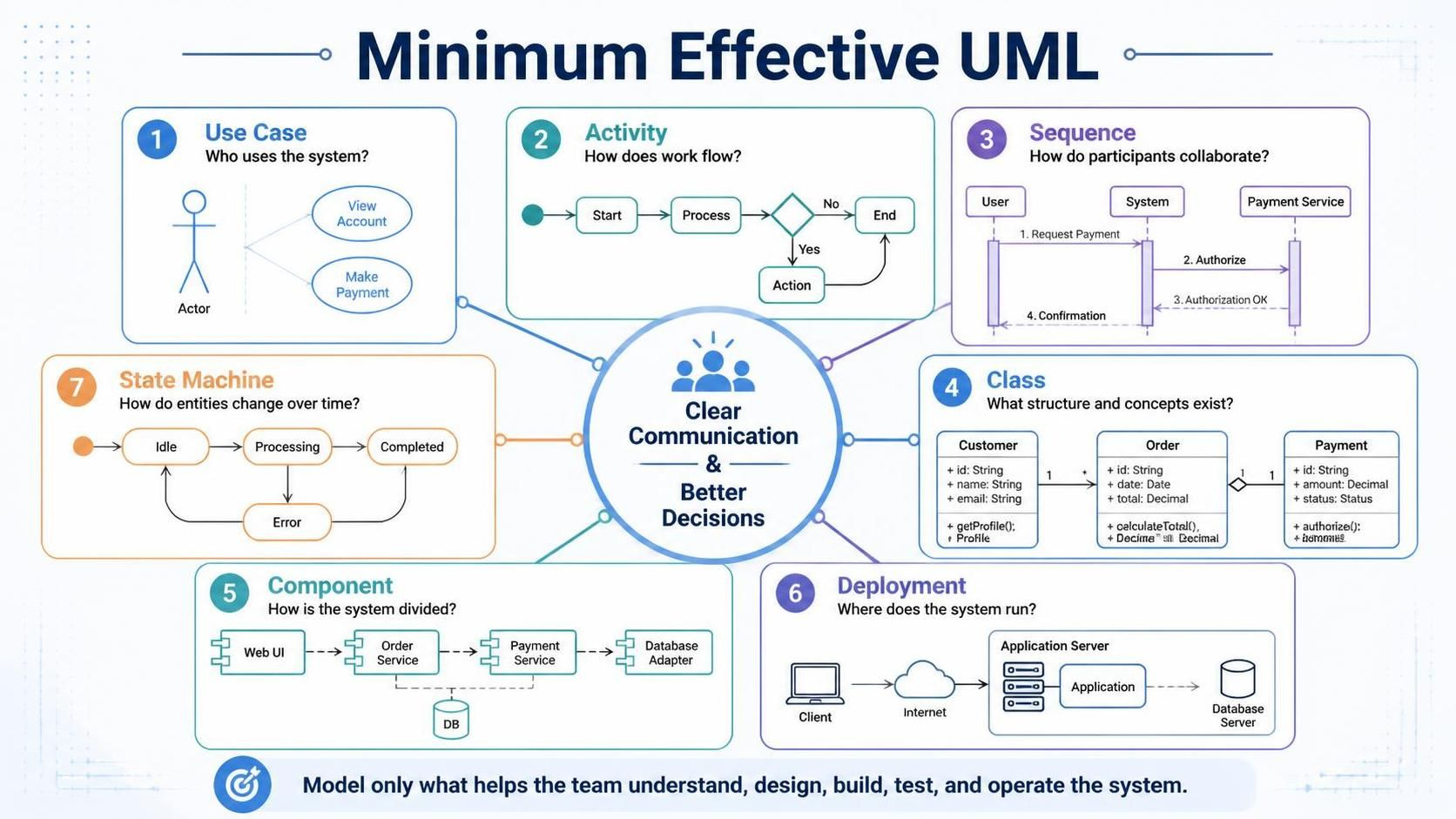
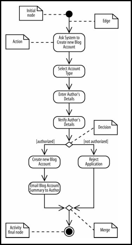
Those details are better represented with activity, class, sequence, or state diagrams.
2. Key Concepts
System Boundary
The system boundary is a rectangle surrounding the use cases that belong to the system.
For example, in an online shopping system:
+--------------------------------------+
|        Online Shopping System        |
|                                      |
|  (Browse Products)                   |
|  (Place Order)                       |
|  (Make Payment)                      |
+--------------------------------------+
Actors remain outside the boundary because they are external to the system.
The boundary helps clarify the scope of the system. If a capability is outside the boundary, it is not implemented by the system being modeled.
Actors
An actor is anything external that interacts with the system to achieve a goal.
Actors can include:
-
Human users
-
External applications
-
Hardware devices
-
Other organizations
-
Time or scheduled events, when modeled as external triggers
Examples:
-
Customer
-
Librarian
-
Payment Gateway
-
Administrator
-
Email Service
An actor represents a role, not necessarily a specific person. For example, “Customer” is usually better than “Alex.”
Actors can be:
-
Primary actors — initiate interactions to achieve a goal.
-
Supporting actors — provide services to the system.
For example, a customer may initiate “Place Order,” while a payment gateway supports “Process Payment.”
Use Cases
A use case represents a meaningful goal or service provided by the system.
Good use case names usually follow this form:
Verb + object
Examples:
-
Register Account
-
Search Catalog
-
Submit Application
-
Generate Report
-
Cancel Reservation
-
Process Payment
A use case should describe an observable result, rather than an internal implementation step.
Prefer:
Place Order
over:
Validate Order Object
The second describes an internal operation rather than a user goal.
Associations
An association is a communication link between an actor and a use case.
It indicates that the actor participates in or initiates the use case.
Customer ---- (Place Order)
Associations do not normally indicate sequence, control flow, or direction. If the order of interactions matters, use a sequence or activity diagram.
3. Relationships Between Use Cases
<<include>>
Use <<include>> when one use case always uses another use case.
For example, placing an order may always require authentication:
(Place Order) ..> (Authenticate Customer) : <<include>>
The base use case depends on the included use case.
Use include when:
-
The behavior is mandatory.
-
The behavior is reused by multiple use cases.
-
Extracting the behavior improves clarity.
Example:
(Withdraw Cash) ..> (Authenticate Card) : <<include>>
(Check Balance) ..> (Authenticate Card) : <<include>>
Both use cases always require card authentication.
<<extend>>
Use <<extend>> when additional behavior is optional or conditionally inserted into a base use case.
(Apply Discount) ..> (Place Order) : <<extend>>
The discount behavior occurs only when eligibility conditions are satisfied.
Use extend when:
-
The behavior is optional.
-
It occurs only under a condition.
-
The base use case is complete without it.
Examples:
-
“Add Gift Wrapping” extends “Place Order.”
-
“Request Refund” extends “Cancel Subscription.”
-
“Send Promotional Email” extends “Complete Registration.”
The arrow points from the extending use case to the base use case.
Generalization
Generalization represents an “is-a” relationship between actors or use cases.
For example:
Premium Customer --|> Customer
A premium customer is a kind of customer and inherits the customer’s interactions.
Actor generalization can be useful when several actors share common behavior:
Administrator --|> Employee
Librarian --|> Employee
Use generalization sparingly. If the relationship is merely “uses” or “participates in,” an association is usually more appropriate.
4. Primary and Supporting Actors
Consider an online payment scenario:
-
The Customer is the primary actor because they initiate the purchase.
-
The Payment Gateway is a supporting actor because it processes payment at the system’s request.
A simple model might look like this:
Customer ---- (Place Order)
(Place Order) ---- Payment Gateway
The distinction is useful because it clarifies who benefits from the use case and which external systems are involved.
5. How to Identify Use Cases
A practical way to discover use cases is to ask:
-
Who uses the system?
-
What goal does each actor want to achieve?
-
What services does the system provide?
-
What events trigger system behavior?
-
What external systems must the system interact with?
-
What behavior is always required?
-
What behavior is optional or conditional?
For each actor, list their goals:
| Actor | Goal | Possible Use Case |
|---|---|---|
| Customer | Find a product | Search Products |
| Customer | Buy a product | Place Order |
| Customer | Pay for an order | Make Payment |
| Administrator | Maintain product data | Manage Catalog |
| Payment Gateway | Authorize payment | Process Payment |
The goal should be meaningful to the actor. Avoid turning every small system operation into a use case.
6. Naming Guidelines
Use clear, goal-oriented names.
Good examples:
-
Create Account
-
Update Profile
-
Submit Claim
-
Track Shipment
-
Approve Request
-
Generate Invoice
Avoid vague names:
-
System Processing
-
Handle Data
-
User Function
-
Run Operation
Avoid excessive technical detail:
-
Execute SQL Query
-
Call REST Endpoint
-
Instantiate PaymentService
These may be valid implementation steps, but they are usually not useful as high-level use cases.
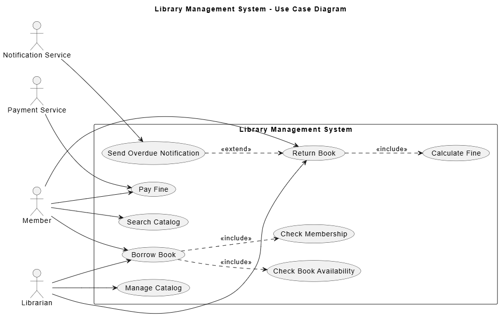
7. Example: Library Management System
Suppose a library system supports:
-
Members searching for books
-
Members borrowing books
-
Members returning books
-
Librarians managing the catalog
-
Overdue notifications
-
Payment processing for fines
Possible actors:
-
Member
-
Librarian
-
Notification Service
-
Payment Service
Possible use cases:
-
Search Catalog
-
Borrow Book
-
Return Book
-
Calculate Fine
-
Pay Fine
-
Manage Catalog
-
Send Overdue Notification
Relationships:
-
Borrow Book includes Check Membership.
-
Borrow Book includes Check Book Availability.
-
Return Book includes Calculate Fine.
-
Pay Fine interacts with Payment Service.
-
Send Overdue Notification interacts with Notification Service.
8. PlantUML Example
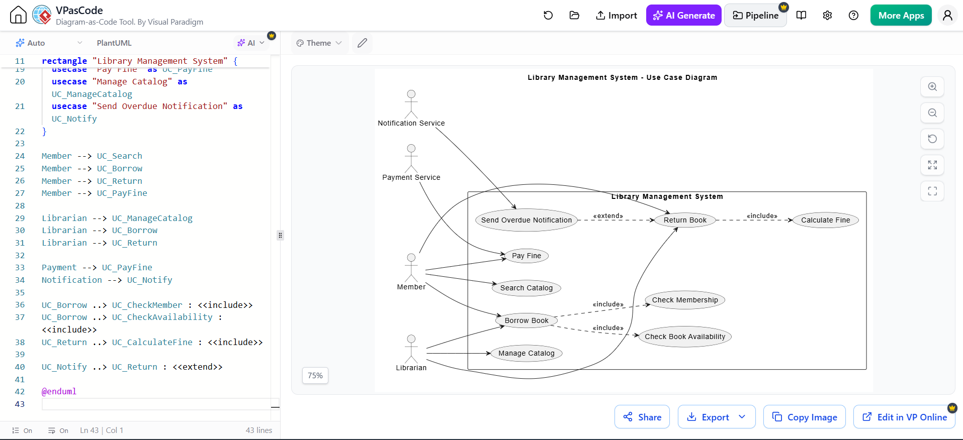
The following PlantUML code creates a use case diagram for the library system:
@startuml
left to right direction

title Library Management System - Use Case Diagram

actor Member
actor Librarian
actor "Notification Service" as Notification
actor "Payment Service" as Payment

rectangle "Library Management System" {

  usecase "Search Catalog" as UC_Search
  usecase "Borrow Book" as UC_Borrow
  usecase "Return Book" as UC_Return
  usecase "Check Membership" as UC_CheckMember
  usecase "Check Book Availability" as UC_CheckAvailability
  usecase "Calculate Fine" as UC_CalculateFine
  usecase "Pay Fine" as UC_PayFine
  usecase "Manage Catalog" as UC_ManageCatalog
  usecase "Send Overdue Notification" as UC_Notify
}

Member --> UC_Search
Member --> UC_Borrow
Member --> UC_Return
Member --> UC_PayFine

Librarian --> UC_ManageCatalog
Librarian --> UC_Borrow
Librarian --> UC_Return

Payment --> UC_PayFine
Notification --> UC_Notify

UC_Borrow ..> UC_CheckMember : <<include>>
UC_Borrow ..> UC_CheckAvailability : <<include>>
UC_Return ..> UC_CalculateFine : <<include>>

UC_Notify ..> UC_Return : <<extend>>

@enduml
9. Explanation of the Example
Actors
actor Member
actor Librarian
actor "Notification Service" as Notification
actor "Payment Service" as Payment
The diagram models two human actors and two external services.
Aliases such as as Notification make long names easier to reference later.
System Boundary
rectangle "Library Management System" {
    ...
}
The rectangle defines the scope of the system. The use cases inside the rectangle are provided by the library system.
Actor Associations
Member --> UC_Search
Member --> UC_Borrow
These associations show that a member can search the catalog and borrow books.
The arrow direction is not usually semantically important in a basic use case diagram. It is primarily used to make the diagram readable.
Include Relationships
UC_Borrow ..> UC_CheckMember : <<include>>
UC_Borrow ..> UC_CheckAvailability : <<include>>
Borrowing a book always requires membership and availability checks, so these are modeled as included use cases.
Extending Relationship
This indicates that overdue notification behavior is additional behavior associated with returning a book.
However, in a real requirements model, a more natural design might be to associate “Send Overdue Notification” with a scheduled process or an actor such as “Library Scheduler.” The best relationship depends on the actual business rules.
10. A More Detailed Use Case Specification
A diagram gives an overview, but each important use case should usually have a textual specification.
Use Case: Borrow Book
| Field | Description |
|---|---|
| Name | Borrow Book |
| Primary actor | Member |
| Supporting actor | Librarian |
| Goal | Borrow an available book |
| Preconditions | Member is registered; book exists |
| Trigger | Member requests to borrow a book |
| Main flow | System verifies membership, checks availability, records the loan, and updates book status |
| Alternative flow | Book is unavailable |
| Alternative flow | Membership is expired |
| Postconditions | Loan is recorded and book is marked as borrowed |
A use case diagram should not try to contain all of this detail. The diagram provides the map; the specification provides the behavior.
11. PlantUML Syntax Reference
Declaring Actors
actor Customer
actor "Payment Gateway" as Gateway
Declaring Use Cases
usecase "Place Order" as PlaceOrder
usecase "Process Payment" as ProcessPayment
Creating a System Boundary
rectangle "Online Store" {
    usecase "Browse Products" as Browse
    usecase "Place Order" as Order
}
Connecting Actors and Use Cases
Include
Extend
Actor Generalization
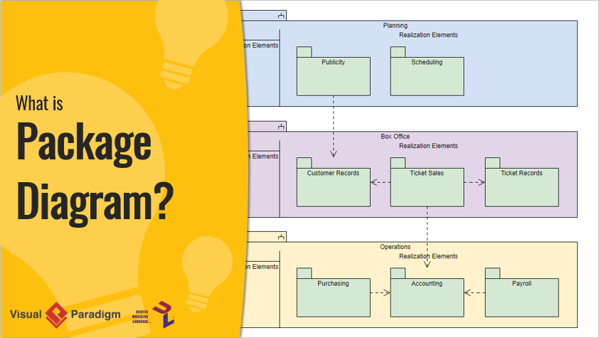
Package Grouping
Packages can visually group related use cases:
rectangle "Banking System" {
  package "Account Management" {
    usecase "Open Account" as OpenAccount
    usecase "Close Account" as CloseAccount
  }

  package "Payments" {
    usecase "Transfer Funds" as TransferFunds
    usecase "Pay Bill" as PayBill
  }
}
Notes
note right of PlaceOrder
  The customer must be authenticated
  before placing an order.
end note
12. Improving Diagram Layout
PlantUML automatically lays out diagrams, but several techniques improve readability.
Control Direction
This is often useful when actors should appear on the sides and use cases in the center.
Other common directions include:
Use Aliases
Instead of repeating long names:
usecase "Verify Customer Identity" as VerifyIdentity
Then reference:
RegisterAccount ..> VerifyIdentity : <<include>>
Group Related Use Cases
Use packages or nested rectangles to separate functional areas:
package "Order Management" {
    usecase "Create Order" as CreateOrder
    usecase "Cancel Order" as CancelOrder
}
Avoid Excessive Crossings
A diagram becomes difficult to read when too many lines cross. You can improve it by:
-
Placing related actors near their use cases
-
Grouping use cases into packages
-
Splitting one large diagram into several smaller diagrams
-
Using aliases for clear references
-
Avoiding unnecessary relationships
13. Common Mistakes
Modeling Internal Functions as Use Cases
This is usually too technical:
Validate Database Connection
Serialize Request
Call Payment API
Prefer externally meaningful goals:
Make Payment
Submit Application
Generate Report
Treating Every Actor as a Person
External systems and devices can also be actors:
-
Payment Gateway
-
Identity Provider
-
Warehouse System
-
Barcode Scanner
-
Notification Service
Using include for Optional Behavior
If behavior is optional, use extend rather than include.
Incorrect:
Place Order ..> Apply Coupon : <<include>>
If applying a coupon is optional, use:
Apply Coupon ..> Place Order : <<extend>>
Using extend for Mandatory Behavior
If a behavior always occurs, it should generally be modeled with include.
Place Order ..> Authenticate Customer : <<include>>
Connecting Use Cases Directly Without Meaning
A line between two use cases should represent a valid UML relationship. Avoid arbitrary connections that merely imply that the use cases are somehow related.
Creating One Giant Diagram
A use case diagram should communicate clearly at a high level. If it contains dozens of actors and use cases, create several diagrams organized by subsystem or business area.
Showing Sequence
A use case diagram does not show that one use case happens before another. For sequence, use a sequence diagram or activity diagram.
14. When to Use Other UML Diagrams
Use case diagrams are best for system scope and user goals. Combine them with other diagrams when more detail is needed:
| Requirement | Useful Diagram |
|---|---|
| User goals and system scope | Use case diagram |
| Detailed workflow | Activity diagram |
| Interaction order | Sequence diagram |
| Static domain structure | Class diagram |
| Object lifecycle | State machine diagram |
| Deployment architecture | Deployment diagram |
| Components and dependencies | Component diagram |
15. Recommended Modeling Process
-
Define the system boundary.
-
Identify all external actors.
-
Identify the goals of each actor.
-
Convert those goals into use cases.
-
Connect actors to the use cases they participate in.
-
Identify mandatory reusable behavior and model it with
<<include>>. -
Identify optional or conditional behavior and model it with
<<extend>>. -
Add generalization only where there is a genuine “is-a” relationship.
-
Review the diagram with stakeholders.
-
Add textual specifications for important use cases.
-
Split the diagram if it becomes crowded.
16. Compact PlantUML Template
You can use this as a starting point:
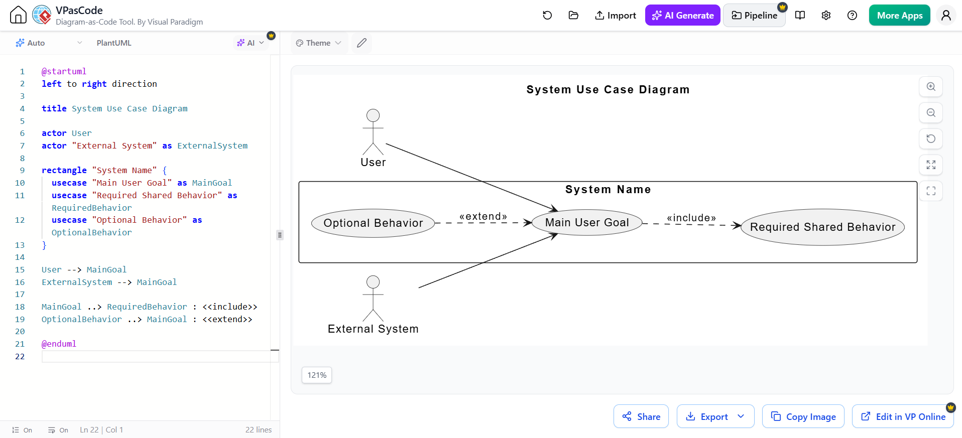
@startuml
left to right direction

title System Use Case Diagram

actor User
actor "External System" as ExternalSystem

rectangle "System Name" {
  usecase "Main User Goal" as MainGoal
  usecase "Required Shared Behavior" as RequiredBehavior
  usecase "Optional Behavior" as OptionalBehavior
}

User --> MainGoal
ExternalSystem --> MainGoal

MainGoal ..> RequiredBehavior : <<include>>
OptionalBehavior ..> MainGoal : <<extend>>

@enduml
The central principle is to model externally visible goals, not internal implementation details. A strong use case diagram makes the system boundary, actors, capabilities, and important dependencies immediately understandable.
Reference
- How to Create UML Use Case Diagram in Visual Paradigm: A step-by-step guide covering actor creation, system boundaries, associations, and include/extend relationships .
- Ultimate Guide to Use Case Diagrams in 2026: Comprehensive guide explaining core notation, best practices, and AI-driven modeling workflows .
- Bridging Requirements and Design: A Practical Guide to Use Case Modeling: Real-world case study demonstrating PlantUML implementation and core modeling concepts .
- Master AI-Driven Use Case Diagrams: A Short Tutorial: Tutorial on using the AI-powered tool to generate and refine use case diagrams from domain descriptions .
- Practical 2: Hands-on Use Case Modeling: Hands-on exercise for building a Library Management System diagram manually and with AI .
- Use Case Diagram Made Easy: Overview of Visual Paradigm’s use case diagram features including flow of events editor and activity diagram generation .