
Introduction
Software architecture is easier to understand, communicate, and maintain when complex requirements are represented visually. UML diagrams, architecture maps, process flows, and data models help teams align before implementation begins. However, traditional diagramming can become slow when every element must be positioned manually and updated by hand.
A more efficient approach combines three practices:
-
UML modeling for structured analysis and design
-
Diagram-as-Code (DaC) for versionable, repeatable diagram creation
-
AI assistance for generating and refining initial models
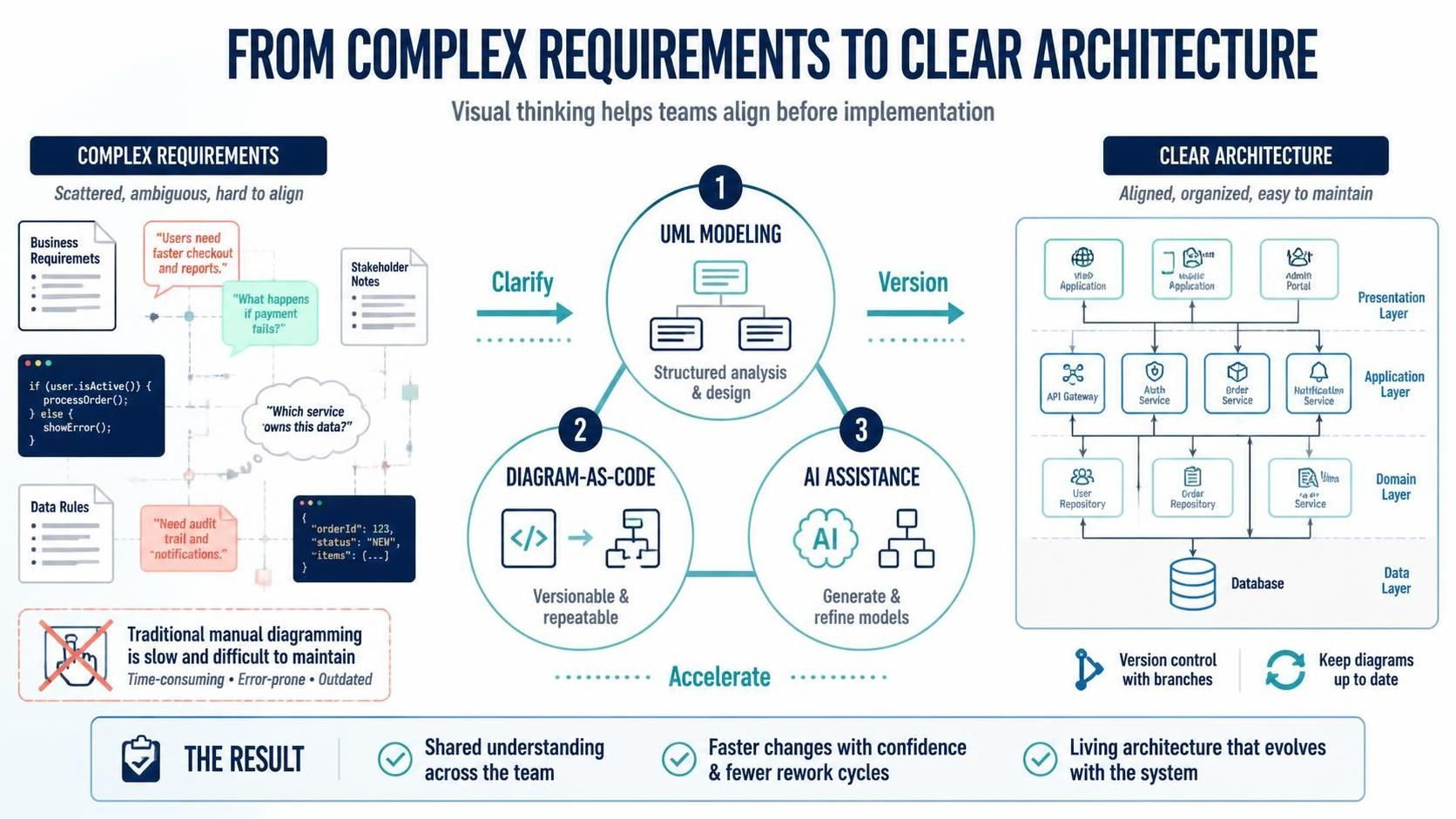
Visual Paradigm brings these practices together through its UML modeling tools, VPasCode text-to-diagram platform, AI diagram-generation features, and documentation integrations. VPasCode supports diagram languages and formats including PlantUML, Mermaid, Graphviz, and other text-based notations, with live rendering beside the source code.
The result is a workflow that moves from a natural-language idea to an editable diagram, then to a more formal model and shareable project documentation.
1. Understanding the Visual Paradigm Tooling Ecosystem
Visual Paradigm UML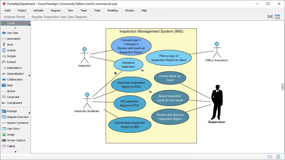
Visual Paradigm’s UML tools are suited to structured software analysis and design. They support common UML perspectives such as:
-
Use case diagrams
-
Class diagrams
-
Sequence diagrams
-
Activity diagrams
-
State-machine diagrams
-
Component diagrams
-
Deployment diagrams
-
Communication diagrams
UML is particularly useful when a team needs more than a quick visual sketch. A UML model can describe system structure, behavior, responsibilities, dependencies, and interactions in a consistent notation.
For example, a class diagram can define:
-
Classes and interfaces
-
Attributes and operations
-
Inheritance
-
Associations
-
Aggregation and composition
-
Multiplicities
-
Dependencies and constraints
VPasCode
VPasCode is Visual Paradigm’s browser-based diagram-as-code workspace. Instead of placing shapes manually, users write or generate text-based diagram definitions and view the rendered result in real time. It supports PlantUML, Mermaid, Graphviz, and other supported formats.
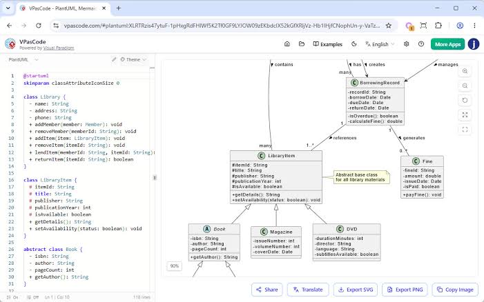
Its main capabilities include:
-
Side-by-side source-code and diagram preview
-
Browser-based editing without local setup
-
Multiple diagram languages in one workspace
-
AI-assisted diagram generation
-
AI-assisted modification
-
Syntax-error fixing
-
Diagram translation
-
Sharing and image export
VPasCode is especially useful for developers, architects, and technical writers who want diagrams to fit naturally into a code-centered workflow.
AI-Assisted Diagram Generation
Visual Paradigm’s AI capabilities can convert natural-language instructions into diagram code. For example, a user can request a sequence diagram for a login flow or a class diagram for an online store. VPasCode can then generate code in a supported format and render the result.
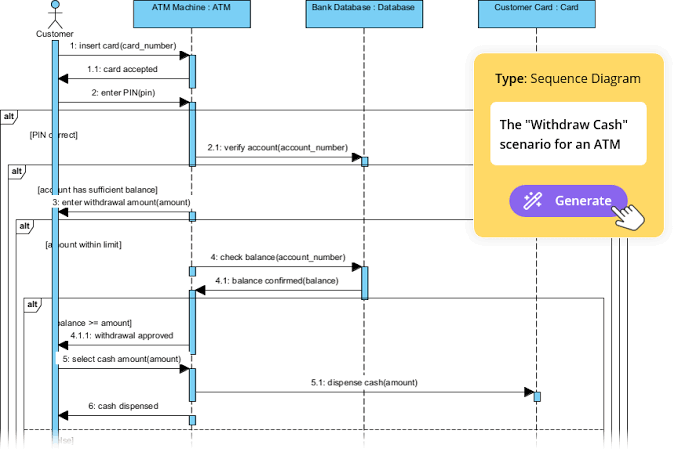
AI can also help modify an existing diagram. Rather than rewriting the complete script, users can issue instructions such as:
-
“Add a payment-failure path.”
-
“Introduce an administrator actor.”
-
“Group the services by bounded context.”
-
“Rename
Process OrdertoValidate and Confirm Order.” -
“Translate all labels into French.”
Generated diagrams should be treated as working drafts. The AI can accelerate modeling, but domain experts still need to verify relationships, terminology, responsibilities, and system boundaries.
2. Key Concepts
UML Modeling
UML is a standardized visual language for describing software systems. Different diagram types answer different questions:
| Diagram type | Primary purpose | Example question |
|---|---|---|
| Use case | Describes user goals and system services | What can each actor do? |
| Class | Describes static structure | What are the system’s entities and relationships? |
| Sequence | Describes time-ordered interactions | Which component calls which service? |
| Activity | Describes workflows and decisions | What happens during an approval process? |
| State machine | Describes lifecycle behavior | How does an order change state? |
| Component | Describes logical software modules | Which services make up the system? |
| Deployment | Describes runtime infrastructure | Where are components deployed? |
A useful modeling process usually starts with a high-level view and progressively adds detail. For example:
-
Identify actors and business goals.
-
Define major domain concepts.
-
Describe important interactions.
-
Map components and integrations.
-
Document deployment and operational concerns.
Diagram-as-Code
Diagram-as-Code represents a diagram as text rather than as a collection of manually positioned shapes. The source file becomes the diagram’s editable definition.
A small PlantUML example:
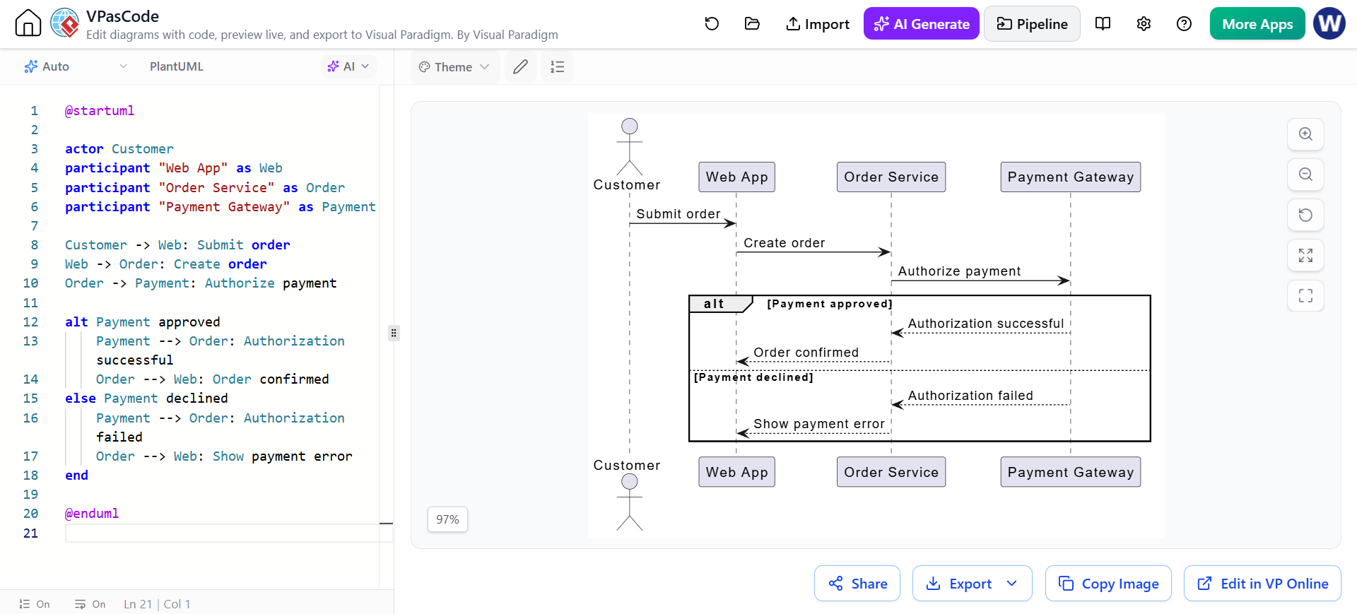
@startuml

actor Customer
participant "Web App" as Web
participant "Order Service" as Order
participant "Payment Gateway" as Payment

Customer -> Web: Submit order
Web -> Order: Create order
Order -> Payment: Authorize payment

alt Payment approved
    Payment --> Order: Authorization successful
    Order --> Web: Order confirmed
else Payment declined
    Payment --> Order: Authorization failed
    Order --> Web: Show payment error
end

@enduml
The advantages include:
-
Version control: Store diagram source in Git.
-
Reviewability: Review changes through pull requests.
-
Repeatability: Regenerate diagrams consistently.
-
Automation: Include diagrams in documentation pipelines.
-
Maintainability: Update text instead of repositioning many shapes.
-
Collaboration: Developers, architects, and technical writers can work with familiar text files.
AI-Assisted Modeling
AI can support several stages of the modeling process:
-
Generation: Create an initial diagram from a description.
-
Modification: Add, remove, or reorganize elements.
-
Correction: Repair syntax problems.
-
Translation: Translate labels while preserving structural syntax.
-
Explanation: Help users understand unfamiliar diagram code.
AI is most effective when prompts specify the diagram type, scope, participants, relationships, and expected level of detail.
3. A Complete Workflow with Visual Paradigm
Phase 1: Describe the System
Begin with a short architectural brief. Include:
-
The system’s purpose
-
Primary users
-
Major services or modules
-
External systems
-
Key business workflows
-
Important success and failure paths
For example:
Create a UML sequence diagram for an e-commerce checkout process. Include Customer, Web Application, Order Service, Inventory Service, Payment Gateway, and Notification Service. Show successful payment, declined payment, and insufficient inventory scenarios.
This is more effective than a vague instruction such as “Create an e-commerce sequence diagram” because it defines the expected participants and behavior.
Phase 2: Generate an Initial Diagram
Use the AI diagram-generation capability in VPasCode or begin with a Visual Paradigm AI diagramming workflow. The generated result provides a starting point rather than a finished architectural specification.
At this stage, inspect the result for:
-
Missing actors or components
-
Incorrect relationships
-
Ambiguous names
-
Unnecessary detail
-
Missing alternative flows
-
Incorrect assumptions about business rules
The purpose of AI generation is to reduce blank-page friction and produce a useful first draft quickly.
Phase 3: Refine the Diagram in VPasCode
Open the generated source in VPasCode and refine it directly. VPasCode provides a live preview, allowing the author to compare code changes with the visual result as the diagram is edited.
A practical refinement sequence is:
-
Rename elements using project terminology.
-
Remove speculative components.
-
Add missing error paths.
-
Clarify relationships and message direction.
-
Group related elements.
-
Add comments to explain unusual decisions.
-
Apply consistent styling.
-
Check that the diagram remains readable at its intended size.
For example, an AI-generated sequence diagram might show only a successful payment. A follow-up instruction could be:
Add an alternative flow for declined payment. The Order Service must mark the order as
PaymentFailed, and the Web Application must display a retry message. Do not change the existing successful-payment flow.
VPasCode also provides AI-assisted syntax correction when a PlantUML, Mermaid, or Graphviz script fails to render. The recommended process is to review the reported error, apply the suggested correction, and inspect the changed source before accepting it.
Phase 4: Validate the Model
A diagram can be syntactically valid and still be architecturally wrong. Validate it against the requirements and implementation assumptions.
Ask:
-
Does every actor have a clear responsibility?
-
Are system boundaries explicit?
-
Are relationships correctly directed?
-
Are multiplicities accurate?
-
Are service calls consistent with the intended architecture?
-
Are error paths represented?
-
Does the diagram show too much implementation detail?
-
Do names match the codebase and domain language?
For a class diagram, verify ownership and cardinality. For a sequence diagram, verify message order and responses. For a deployment diagram, verify that the shown infrastructure reflects the actual runtime environment.
Phase 5: Continue in Visual Paradigm’s Graphical Modeling Tools
Text-based diagrams are excellent for rapid iteration, but a graphical UML environment is often more convenient for detailed model management. Visual Paradigm supports continuing work through graphical editors after a diagram has been generated or imported.
Use the graphical modeling environment when you need to:
-
Add detailed attributes and operations
-
Define data types
-
Set visibility and properties
-
Refine relationships
-
Organize larger models
-
Connect related diagrams
-
Maintain a broader project model
-
Prepare formal documentation
This creates a practical division of labor:
-
VPasCode: fast, text-based, code-friendly creation
-
Visual Paradigm UML tools: detailed graphical modeling and structured refinement
-
OpenDocs or documentation tools: publication and knowledge sharing
Finished diagrams can also be connected to Visual Paradigm documentation workflows, including OpenDocs, to create shareable project knowledge bases.
Phase 6: Publish and Maintain the Documentation
Export diagrams for use in:
-
Architecture decision records
-
Technical specifications
-
API documentation
-
Design reviews
-
Onboarding guides
-
Project wikis
-
Presentations
-
Release documentation
VPasCode supports export formats such as PNG, SVG, and PDF, allowing diagrams to be used in both web and print-oriented documentation.
More importantly, retain the original diagram source. Exported images are presentation artifacts; the source code is the maintainable version.
4. Practical Examples
Example 1: Use Case Diagram for an Online Store
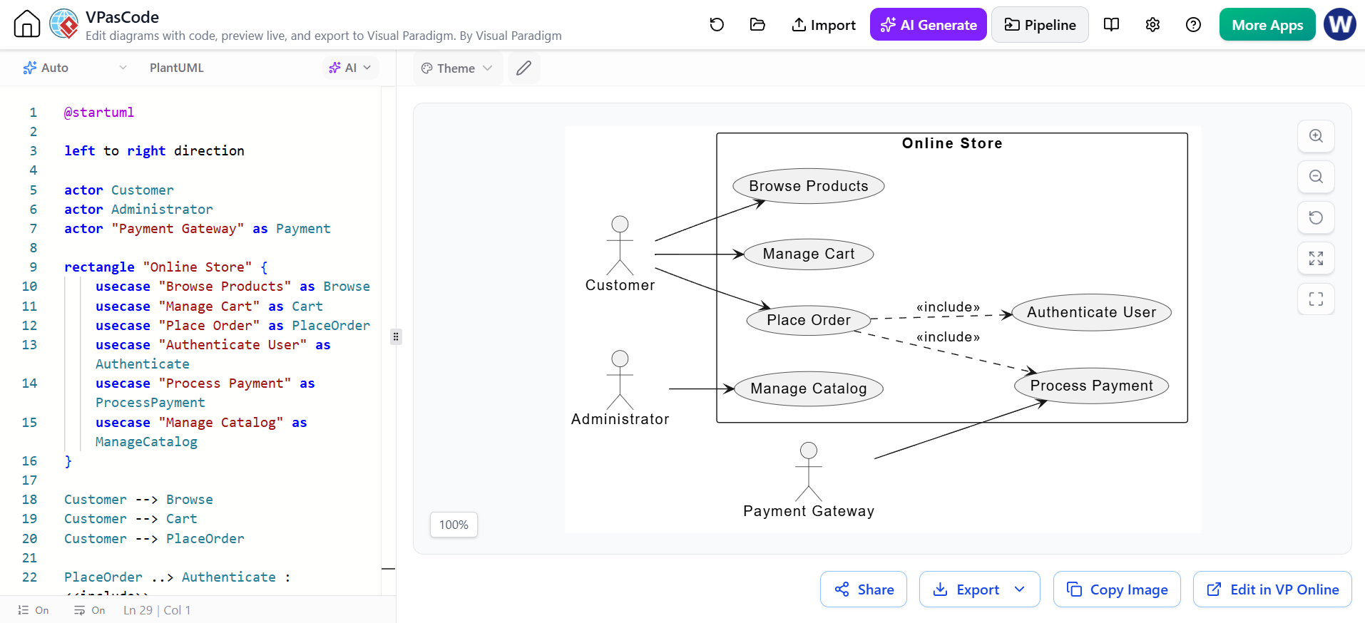
A use case diagram can define the major goals of an online shopping system:
@startuml

left to right direction

actor Customer
actor Administrator
actor "Payment Gateway" as Payment

rectangle "Online Store" {
    usecase "Browse Products" as Browse
    usecase "Manage Cart" as Cart
    usecase "Place Order" as PlaceOrder
    usecase "Authenticate User" as Authenticate
    usecase "Process Payment" as ProcessPayment
    usecase "Manage Catalog" as ManageCatalog
}

Customer --> Browse
Customer --> Cart
Customer --> PlaceOrder

PlaceOrder ..> Authenticate : <<include>>
PlaceOrder ..> ProcessPayment : <<include>>

Payment --> ProcessPayment
Administrator --> ManageCatalog

@enduml
This diagram establishes the system boundary and identifies the primary actors and capabilities. It does not attempt to explain every internal implementation detail.
Example 2: Class Diagram for Ordering
@startuml

class User {
    -id: UUID
    -email: String
    +placeOrder(): Order
}

class Order {
    -orderNumber: String
    -status: OrderStatus
    +calculateTotal(): Money
}

class OrderLine {
    -quantity: Integer
    -unitPrice: Money
}

class Product {
    -sku: String
    -name: String
    -price: Money
}

class Payment {
    -transactionId: String
    -status: PaymentStatus
}

User "1" --> "0..*" Order : places
Order "1" *-- "1..*" OrderLine
OrderLine "*" --> "1" Product
Order "1" --> "0..1" Payment

@enduml
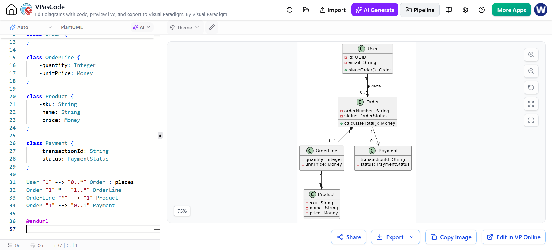
This example communicates ownership and cardinality:
-
A user can place many orders.
-
An order contains one or more order lines.
-
Each order line refers to one product.
-
An order may have zero or one payment record.
The exact relationships should be reviewed against the application’s domain rules. For example, some systems may allow multiple payment attempts for one order, in which case the payment relationship would need to change.
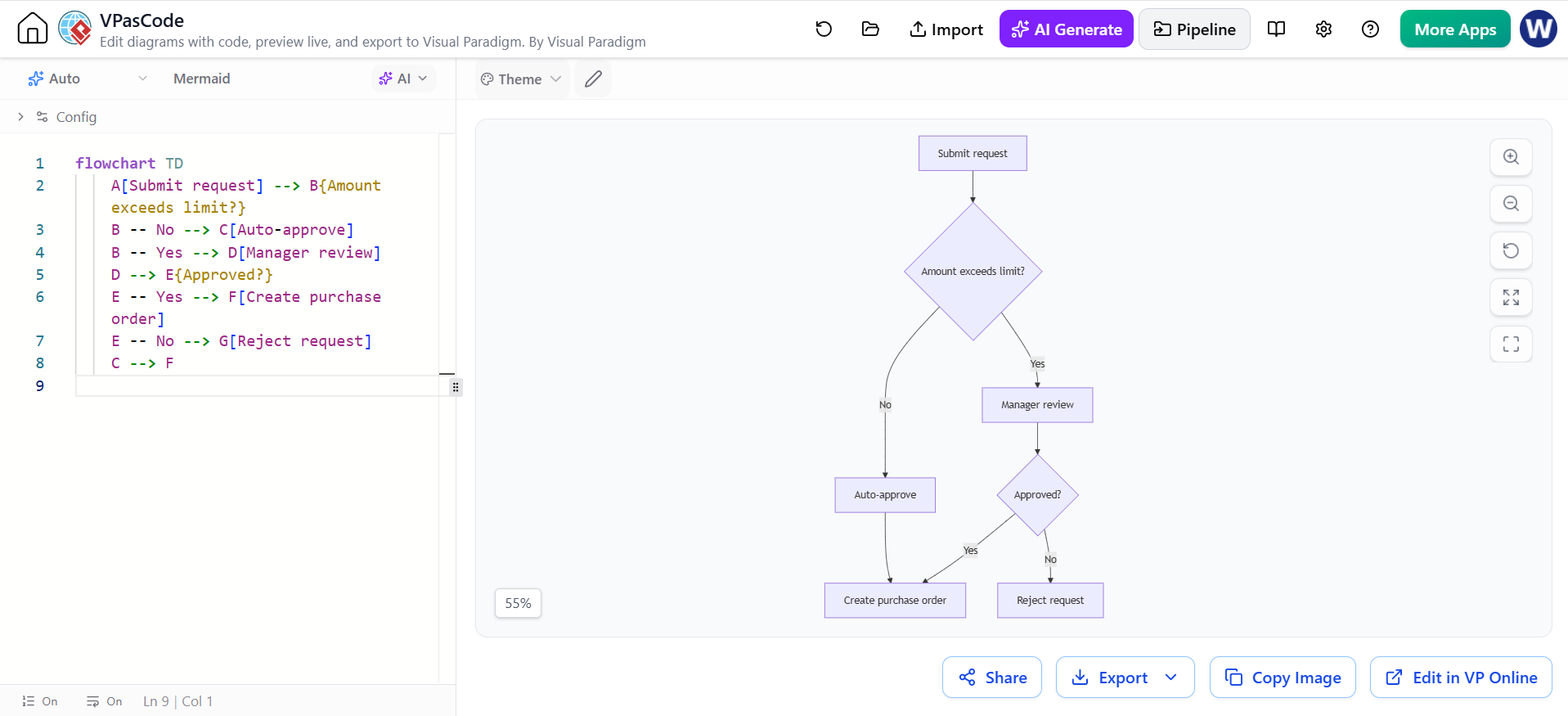
Example 3: Mermaid Flowchart for an Approval Process
flowchart TD
    A[Submit request] --> B{Amount exceeds limit?}
    B -- No --> C[Auto-approve]
    B -- Yes --> D[Manager review]
    D --> E{Approved?}
    E -- Yes --> F[Create purchase order]
    E -- No --> G[Reject request]
    C --> F
Mermaid can be convenient for lightweight flowcharts and documentation pages. PlantUML may be preferable when the team needs broader UML coverage, while Graphviz can be useful for graph-oriented relationships and network structures.
5. Prompting Techniques for Better AI-Generated Diagrams
Specify the Diagram Type
State whether you need a:
-
Class diagram
-
Sequence diagram
-
Activity diagram
-
Use case diagram
-
Component diagram
-
Deployment diagram
-
State diagram
-
Flowchart
Define the Scope
Tell the AI whether the diagram should represent:
-
The entire system
-
One business process
-
One service
-
A single user journey
-
A high-level architecture
-
A detailed implementation interaction
Name the Participants
List the actors, services, entities, or infrastructure nodes that must appear. This reduces the chance that important elements will be omitted or replaced with generic names.
Describe Relationships Explicitly
Use instructions such as:
-
“Customer owns multiple Orders.”
-
“The API Gateway routes requests to the Order Service.”
-
“The Payment Service calls an external payment provider.”
-
“The Order contains one or more Order Lines.”
Include Alternative Paths
For behavior diagrams, specify exceptions and failures:
-
Payment declined
-
Authentication failed
-
Inventory unavailable
-
Timeout
-
Duplicate request
-
Manual approval required
Require Controlled Detail
Useful instructions include:
Create a high-level component diagram. Do not include database tables, method names, or infrastructure-level details.
Or:
Create a detailed sequence diagram showing request, response, validation, persistence, and error handling.
Ask AI to Preserve Existing Structure
When modifying a diagram, use constraints such as:
Add a cancellation flow without changing the existing successful flow or renaming any participants.
This helps limit unintended changes.
6. Best Practices for Teams
Keep Diagram Source in Version Control
Store PlantUML, Mermaid, Graphviz, or other source files alongside the relevant application or documentation project. Use meaningful names such as:
docs/
  architecture/
    checkout-sequence.puml
    order-domain.puml
    deployment-overview.puml
Review diagram changes through the same process used for source code.
Separate Conceptual and Detailed Diagrams
Avoid forcing every detail into one diagram. Maintain separate views for:
-
Business capabilities
-
Domain structure
-
Service interactions
-
Infrastructure deployment
-
Operational processes
A concise diagram is usually more useful than an exhaustive one.
Use Consistent Naming
Choose one vocabulary for actors, services, entities, and operations. For example, do not alternate between:
-
Order Service -
Ordering Service -
Purchase Service
unless these are genuinely different components.
Treat AI Output as a Draft
AI can produce plausible but incorrect relationships. Review:
-
Cardinalities
-
Inheritance
-
Dependencies
-
Sequence order
-
Security boundaries
-
Failure handling
-
Data ownership
The human modeler remains responsible for the technical accuracy of the final result.
Preserve the Source of Truth
Do not make changes only to an exported image. Update the diagram source and regenerate the visual artifact. This prevents documentation from becoming disconnected from its editable definition.
Choose the Right Diagram Language
Use PlantUML when you need extensive UML support. Use Mermaid when diagrams will be embedded in Markdown-oriented documentation. Use Graphviz when graph layout and node relationships are the primary concern. VPasCode allows these formats to be worked with in a unified environment.
7. Common Mistakes to Avoid
Starting with Too Much Detail
A first diagram containing every class, endpoint, database table, and infrastructure node is difficult to review. Start with the most important concepts, then create focused follow-up diagrams.
Confusing Diagram Validity with Model Validity
A diagram may render successfully while representing an incorrect design. Always validate the result against requirements and implementation reality.
Using AI Without Constraints
Prompts such as “Design my whole system” usually produce inconsistent scope and unnecessary assumptions. Define the actors, boundaries, diagram type, and expected level of detail.
Mixing Abstraction Levels
Avoid placing business actors, Java classes, cloud regions, and database columns in the same high-level diagram unless the purpose specifically requires it.
Neglecting Failure Scenarios
A happy-path-only sequence diagram can hide the most important design decisions. Include rejected payments, unavailable inventory, timeouts, retries, and authorization failures where relevant.
Conclusion
Combining UML, Diagram-as-Code, and AI creates a practical modeling workflow for modern software teams. AI reduces the effort required to produce an initial draft, VPasCode provides fast text-based editing and live rendering, and Visual Paradigm’s UML tools support deeper refinement and structured model development.
A productive workflow is:
-
Describe the system in natural language.
-
Generate an initial diagram with AI.
-
Refine the diagram as code in VPasCode.
-
Validate the model against requirements.
-
Continue detailed work in Visual Paradigm’s graphical UML environment.
-
Publish the result as maintainable project documentation.
-
Store the source under version control and update it as the system evolves.
Used together, these tools turn architecture documentation from a one-time drawing exercise into a repeatable engineering practice—one that is faster to update, easier to review, and better aligned with the software it describes.
Related posts:
 Visual Paradigm AI: Generate Professional UML Use Case Diagrams from Text in Seconds
 GourmetReserve Development Simplified: Transforming Requirements with the Best AI-Powered Use Case Modeling Studio
 The Best AI-Powered Database Modeling Tool for Designing Hospital Systems: Visual Paradigm Online
 Automating Student Record System Analysis: From Raw Text to Class Models with Visual Paradigm