
Introduction
Use case diagrams provide a clear way to describe how users, external systems, and other actors interact with a software system. They help teams define system scope, identify functional requirements, and communicate expected behavior before implementation begins.
PlantUML makes use case modeling practical through a text-based syntax that can be stored, reviewed, versioned, and regenerated alongside project documentation or source code. With a few commands, you can define actors, use cases, system boundaries, associations, <<include>> relationships, <<extend>> relationships, generalization, notes, and layout preferences.
This guide explains the key PlantUML use case notation shown in the reference sheet and demonstrates how to apply it in realistic examples. It also introduces a broader tooling workflow using Visual Paradigm UML, AI-assisted modeling, and VPasCode. Together, these tools support a complete process: turning requirements into an initial model, validating UML relationships, refining the diagram, and maintaining the final model as readable diagram source.
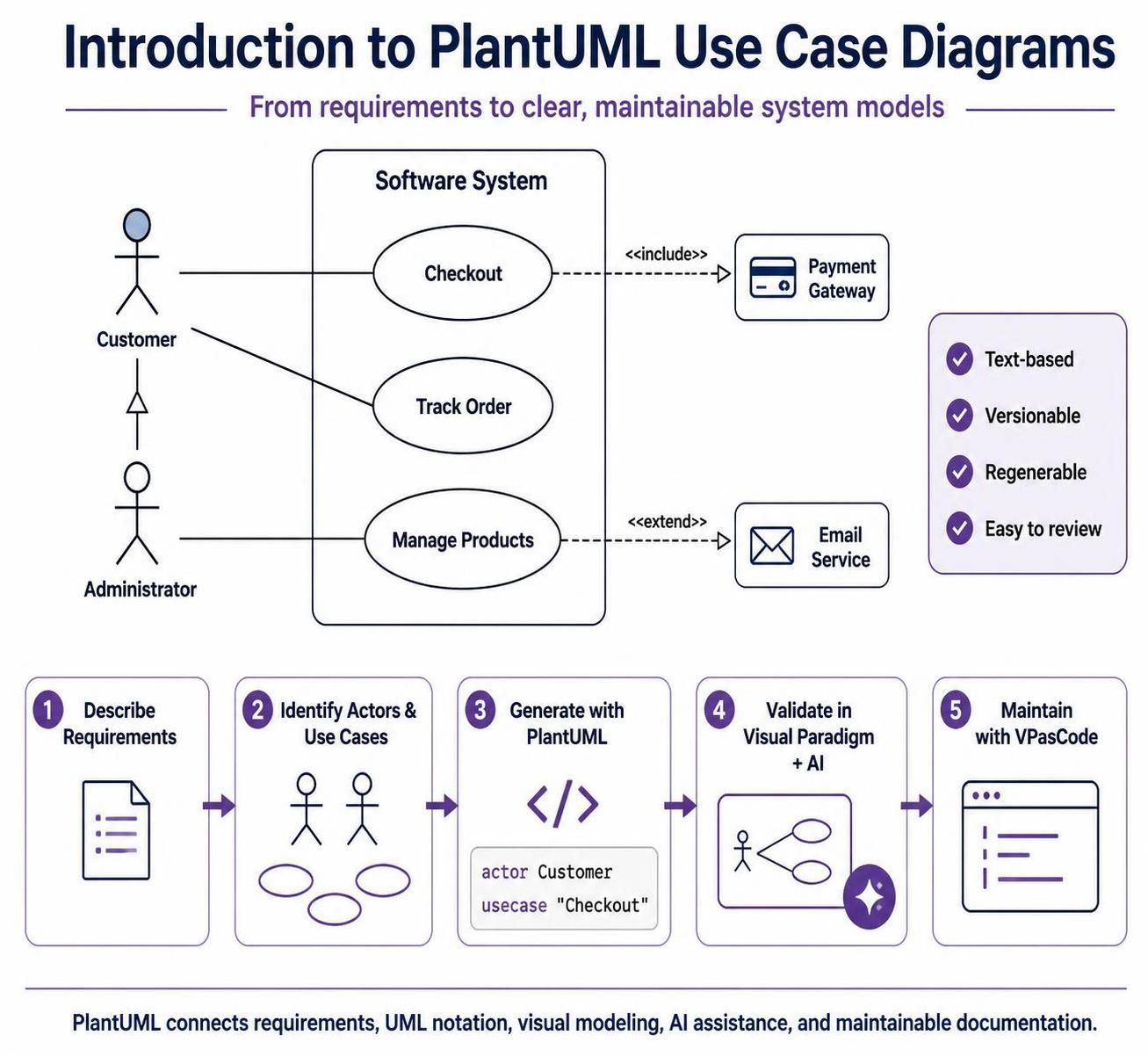 A UML use case diagram describes how external users or systems interact with a system. It focuses on what the system does, rather than how it is implemented.
PlantUML lets you create use case diagrams using simple text-based notation.
1. Basic PlantUML structure
Every PlantUML diagram begins with @startuml and ends with @enduml.
@startuml

' Diagram content goes here

@enduml
Comments begin with an apostrophe:
You can also use multiline comments:
2. Defining actors
An actor represents a person, role, organization, device, or external system that interacts with your system.
Basic actor
This creates a stick-figure actor named User.
Actor with an alias
Aliases are useful when the displayed name contains spaces or when you want a shorter identifier for relationships.
actor "Payment Gateway" as payment
actor "System Administrator" as admin
You can then refer to the aliases:
payment --> ProcessPayment
admin --> ManageUsers
Actor using a different visual style
PlantUML supports several actor styles. The default style is usually sufficient, but you can use an icon-style actor:
skinparam actorStyle awesome

actor Customer
You can also use a plain rectangle-style actor:
skinparam actorStyle hollow

actor Customer
The exact appearance depends on the PlantUML rendering engine and skin parameters.
3. Defining use cases
A use case represents a service, goal, or function provided by the system.
Basic use case
PlantUML renders this as an ellipse labeled Log In.
Use case with an alias
usecase "Process Credit Card Payment" as ProcessPayment
The visible label is Process Credit Card Payment, while ProcessPayment is used in relationships.
actor Customer
Customer --> ProcessPayment
Multiline use-case names
You can insert a line break using \n:
usecase "Process\nCredit Card\nPayment" as ProcessPayment
This is useful when a diagram contains long labels.
4. System boundaries
A system boundary groups the use cases that belong to a particular system.
rectangle "Online Shopping System" {
    usecase "Browse Products" as Browse
    usecase "Checkout" as Checkout
}
The rectangle represents the system, and the use cases inside it represent the functionality provided by that system.
You can also use a named alias for the boundary:
rectangle "Online Shopping System" as OnlineStore {
    usecase "Browse Products" as Browse
    usecase "Checkout" as Checkout
}
A system boundary is useful when distinguishing system behavior from external actors and services.
5. Connecting actors and use cases
An association shows that an actor participates in or interacts with a use case.
Undirected association
This creates a solid line without an arrowhead.
Directed association
This creates a solid line with an arrowhead pointing toward the use case.
Both forms are commonly used. The arrow direction should be chosen consistently according to the communication or responsibility you want to emphasize.
Association with a label
The label describes the interaction.
Customer --> ViewOrders : views order history
For a more readable layout, you can use a longer arrow:
6. The <<include>> relationship
An include relationship represents behavior that is always required by another use case.
For example, placing an order may always require payment validation:
PlaceOrder ..> ValidatePayment : <<include>>
The direction is important:
Base use case ..> Included use case : <<include>>
The arrow points from the use case that needs the behavior to the use case that provides the reusable behavior.
Example
usecase "Checkout" as Checkout
usecase "Validate Customer Details" as ValidateCustomer
usecase "Calculate Order Total" as CalculateTotal
usecase "Make Payment" as MakePayment

Checkout ..> ValidateCustomer : <<include>>
Checkout ..> CalculateTotal : <<include>>
Checkout ..> MakePayment : <<include>>
This means:
-
Checkout always validates customer details.
-
Checkout always calculates the order total.
-
Checkout always performs payment.
Use <<include>> when the included behavior is mandatory or reusable.
7. The <<extend>> relationship
An extend relationship represents optional, conditional, or exceptional behavior added to a base use case.
For example, applying a discount may happen only when the customer has a valid coupon:
ApplyDiscount ..> Checkout : <<extend>>
The direction is:
Optional extending use case ..> Base use case : <<extend>>
The arrow points from the optional behavior to the base use case.
Correct example
usecase "Checkout" as Checkout
usecase "Apply Discount Coupon" as ApplyDiscount

ApplyDiscount ..> Checkout : <<extend>>
This means that Apply Discount Coupon optionally extends the Checkout process.
Include and extend compared
| Relationship | Purpose | Arrow direction |
|---|---|---|
<<include>> |
Mandatory reusable behavior | Base use case → included use case |
<<extend>> |
Optional or conditional behavior | Extending use case → base use case |
Example:
Checkout ..> ValidatePayment : <<include>>
ApplyDiscount ..> Checkout : <<extend>>
Avoid reversing these relationships because the direction changes their meaning.
8. Use-case generalization
Generalization shows that one use case is a specialized form of another use case.
usecase "Search Products" as SearchProducts
usecase "Browse Products" as BrowseProducts

SearchProducts -|> BrowseProducts
The hollow triangle points toward the more general use case.
This means that Search Products is a specialized variation of Browse Products.
Generalization is less common than include and extend, so use it only when there is a genuine parent-child relationship between use cases.
9. Actor generalization
Actors can also have generalization relationships.
actor Customer
actor "Premium Customer" as PremiumCustomer

PremiumCustomer -|> Customer
This indicates that a premium customer is a specialized type of customer and inherits the interactions of the general actor.
For example:
10. Notes and annotations
Notes add explanations or constraints to a diagram.
Note attached to a use case
note right of Checkout
  The customer must provide
  valid billing information.
end note
Other positions include:
note left of Checkout
  Customer-facing process
end note

note top of Checkout
  Main business workflow
end note

note bottom of Checkout
  Includes payment processing
end note
Short note syntax
note right of Login : User authentication is required
Standalone note with an alias
note "Payment must be authorized\nbefore the order is confirmed" as PaymentNote
Connect the note to an element with a dashed line:
Notes for constraints
Notes are useful for documenting conditions:
note right of ApplyDiscount
  Optional behavior:
  used only when a valid
  coupon is supplied.
end note
11. Layout direction
By default, PlantUML chooses a layout automatically. You can influence the direction.
Left-to-right layout
This is often useful for use case diagrams because actors appear on the left and external systems on the right.
Top-to-bottom layout
This can be useful for compact diagrams or vertically organized workflows.
Invisible layout links
An invisible link can influence positioning without displaying a visible relationship:
This is useful for improving diagram layout.
12. Styling the diagram
Remove shadows
Use rectangular packages and boundaries
Set colors
skinparam usecase {
    BackgroundColor #FDFDFD
    BorderColor #333333
}

skinparam actor {
    BorderColor #333333
}
Set arrow colors
Set default font size
A complete styling section might look like this:
skinparam shadowing false
skinparam packageStyle rectangle
skinparam actorStyle awesome
skinparam defaultFontSize 14

skinparam usecase {
    BackgroundColor #F9FBFF
    BorderColor #234
}

skinparam ArrowColor #555555
13. Packages and grouping
Packages can group related use cases.
package "Customer Features" {
    usecase "Register Account" as Register
    usecase "Log In" as Login
    usecase "Browse Products" as Browse
}

package "Administration Features" {
    usecase "Manage Products" as ManageProducts
    usecase "Generate Sales Report" as SalesReport
}
Packages are helpful when a diagram contains many use cases.
You can also use a rectangle as a group:
rectangle "Order Management" {
    usecase "Place Order" as PlaceOrder
    usecase "Track Order" as TrackOrder
    usecase "Cancel Order" as CancelOrder
}
14. External systems
External applications or services can be represented as actors.
actor "Payment Gateway" as PaymentGateway
actor "Email Service" as EmailService
actor "External CRM" as CRM
Connect them to system use cases:
PaymentGateway --> MakePayment
EmailService --> SendConfirmation
CRM --> SynchronizeCustomer
This clearly separates system functionality from services outside the system boundary.
15. Complete example
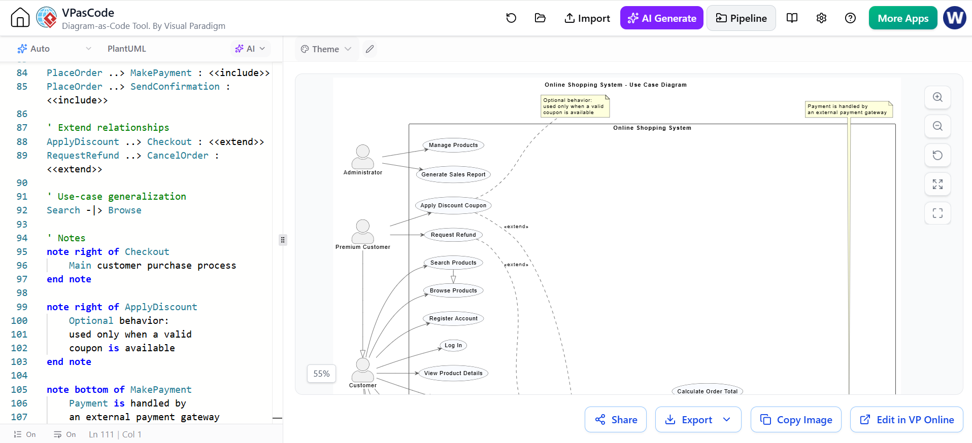
The following example combines the main notation from the reference sheet.
@startuml
title Online Shopping System - Use Case Diagram

left to right direction

skinparam shadowing false
skinparam packageStyle rectangle
skinparam actorStyle awesome

skinparam usecase {
    BackgroundColor #F9FBFF
    BorderColor #333333
}

skinparam ArrowColor #555555

' Actors
actor Customer as customer
actor "Premium Customer" as premium
actor Administrator as admin
actor "Payment Gateway" as payment
actor "Email Service" as email

' Actor generalization
premium -|> customer

' System boundary
rectangle "Online Shopping System" {

    ' Customer use cases
    usecase "Register Account" as Register
    usecase "Log In" as Login
    usecase "Browse Products" as Browse
    usecase "Search Products" as Search
    usecase "View Product Details" as ViewProduct
    usecase "Add Product to Cart" as AddToCart
    usecase "View Shopping Cart" as ViewCart
    usecase "Checkout" as Checkout
    usecase "Place Order" as PlaceOrder
    usecase "Track Order" as TrackOrder
    usecase "Cancel Order" as CancelOrder

    ' Shared included behavior
    usecase "Validate Customer Details" as ValidateCustomer
    usecase "Calculate Order Total" as CalculateTotal
    usecase "Make Payment" as MakePayment
    usecase "Send Order Confirmation" as SendConfirmation

    ' Optional behavior
    usecase "Apply Discount Coupon" as ApplyDiscount
    usecase "Request Refund" as RequestRefund

    ' Administration use cases
    usecase "Manage Products" as ManageProducts
    usecase "Generate Sales Report" as SalesReport
}

' Actor associations
customer --> Register
customer --> Login
customer --> Browse
customer --> Search
customer --> ViewProduct
customer --> AddToCart
customer --> ViewCart
customer --> Checkout
customer --> TrackOrder
customer --> CancelOrder

premium --> ApplyDiscount
premium --> RequestRefund

admin --> ManageProducts
admin --> SalesReport

payment --> MakePayment
email --> SendConfirmation

' Include relationships
Checkout ..> ValidateCustomer : <<include>>
Checkout ..> CalculateTotal : <<include>>
Checkout ..> PlaceOrder : <<include>>

PlaceOrder ..> MakePayment : <<include>>
PlaceOrder ..> SendConfirmation : <<include>>

' Extend relationships
ApplyDiscount ..> Checkout : <<extend>>
RequestRefund ..> CancelOrder : <<extend>>

' Use-case generalization
Search -|> Browse

' Notes
note right of Checkout
    Main customer purchase process
end note

note right of ApplyDiscount
    Optional behavior:
    used only when a valid
    coupon is available
end note

note bottom of MakePayment
    Payment is handled by
    an external payment gateway
end note

@enduml
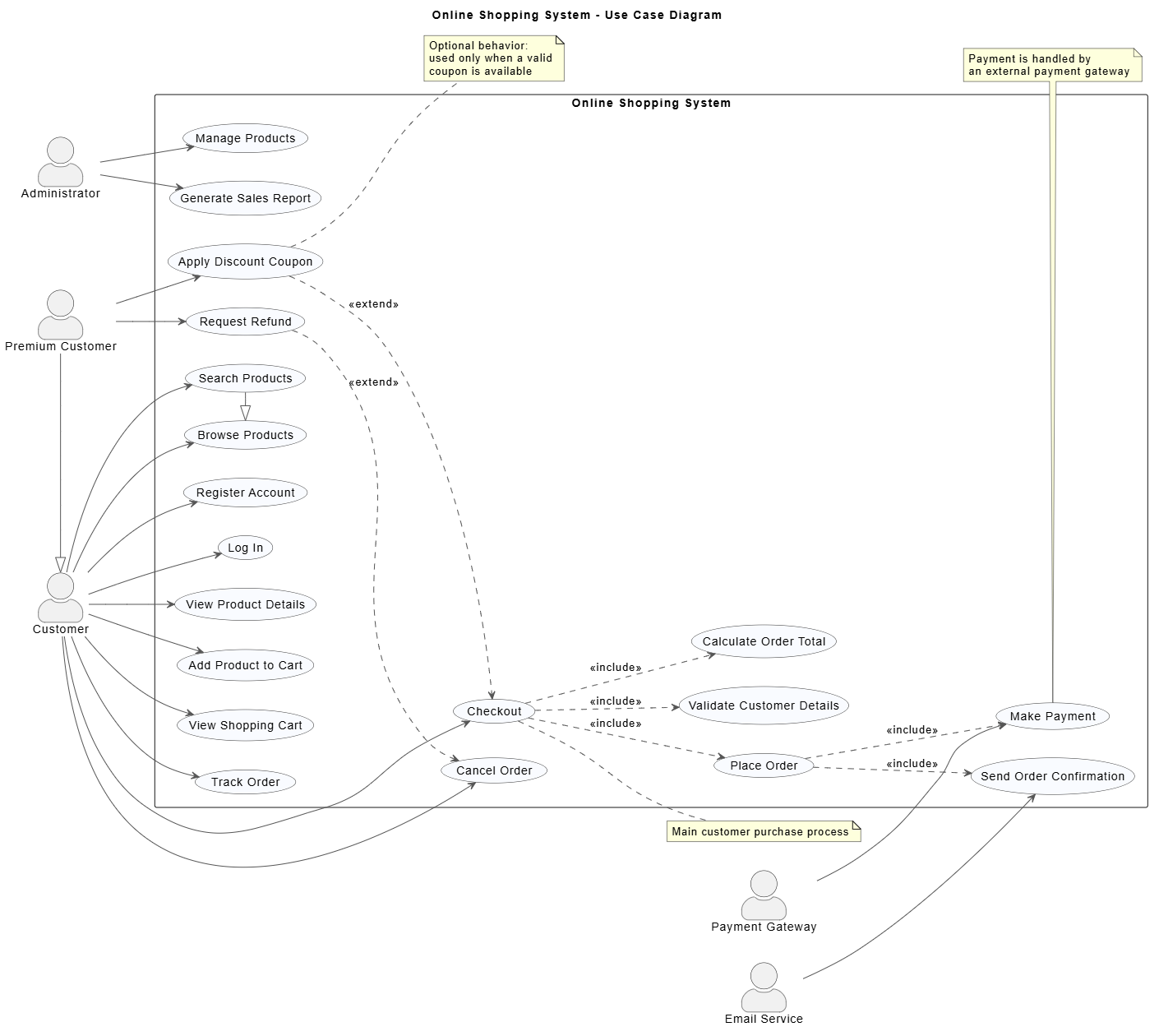
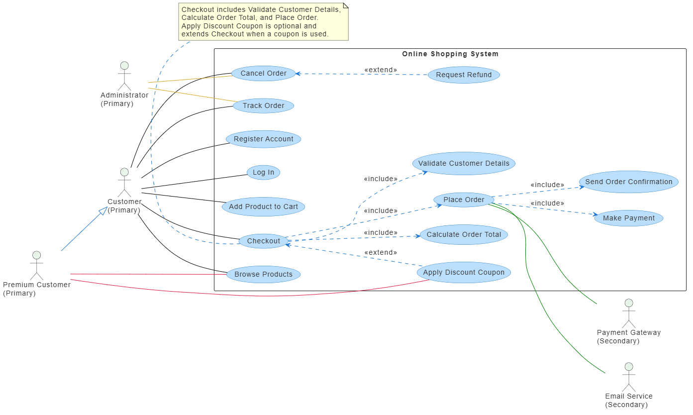
16. Reading the complete example
The diagram communicates the following:
-
Customercan browse products, add products to a cart, and check out. -
Premium Customeris a specialized form ofCustomer. -
Checkoutalways includes customer validation, total calculation, and order placement. -
Place Orderalways includes payment and confirmation. -
Apply Discount Couponis optional and extends checkout. -
Request Refundis an optional extension of cancellation. -
The payment gateway handles payment processing.
-
The email service sends order confirmations.
-
The administrator manages products and generates reports.
17. Common mistakes
Reversing include
Incorrect:
ValidateCustomer ..> Checkout : <<include>>
Correct:
Checkout ..> ValidateCustomer : <<include>>
The base use case points to the required included behavior.
Reversing extend
Incorrect:
Checkout ..> ApplyDiscount : <<extend>>
Correct:
ApplyDiscount ..> Checkout : <<extend>>
The optional extending use case points to the base use case.
Using include for optional behavior
If a behavior happens only under certain conditions, use <<extend>>:
ApplyDiscount ..> Checkout : <<extend>>
If it always happens, use <<include>>:
Checkout ..> ValidateCustomer : <<include>>
Placing external actors inside the system boundary
External users and services should normally be outside the rectangle:
actor Customer

rectangle "Shopping System" {
    usecase "Checkout" as Checkout
}

Customer --> Checkout
Creating overly detailed use cases
A use case should describe a meaningful user goal, such as:
Avoid turning every small implementation step into a separate use case unless it is reused, optional, or important to the model.
18. Minimal practical template
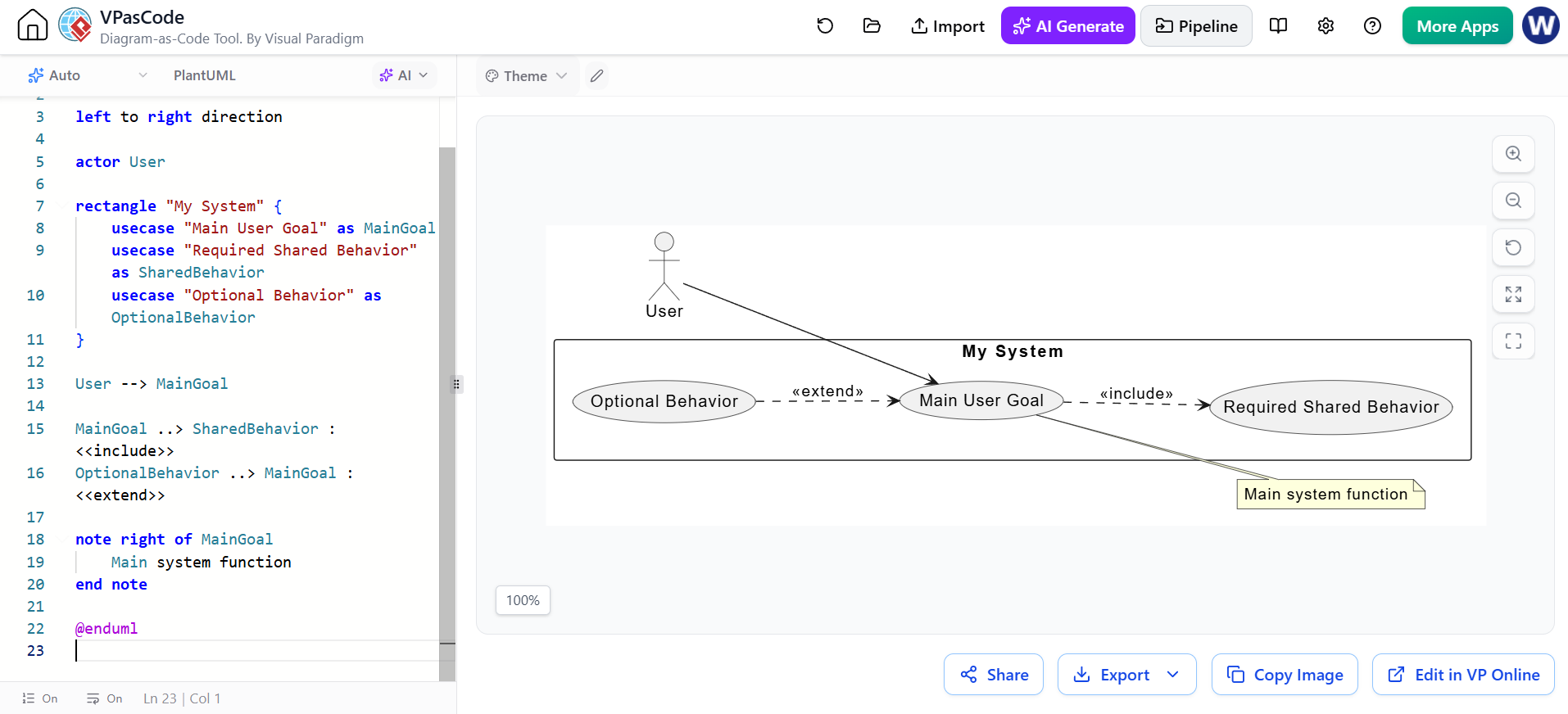
For a smaller diagram, use this template:
@startuml

left to right direction

actor User

rectangle "My System" {
    usecase "Main User Goal" as MainGoal
    usecase "Required Shared Behavior" as SharedBehavior
    usecase "Optional Behavior" as OptionalBehavior
}

User --> MainGoal

MainGoal ..> SharedBehavior : <<include>>
OptionalBehavior ..> MainGoal : <<extend>>

note right of MainGoal
    Main system function
end note

@enduml
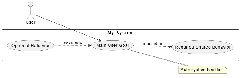
This template contains the essential notation:
-
Actor
-
System boundary
-
Use cases
-
Association
-
Include
-
Extend
-
Note
-
Layout direction
Tooling: Visual Paradigm UML, AI, and VPasCode
PlantUML is ideal for creating diagrams as text, but visual modeling tools can make the same workflow easier to review, refine, and share. Visual Paradigm provides UML modeling capabilities alongside AI-assisted modeling and a text-based VPasCode workspace. Its platform supports standard UML diagrams, including use case, class, sequence, activity, component, deployment, state-machine, package, and object diagrams.
Visual Paradigm UML modeling
Visual Paradigm can be used when you want to build a use case diagram visually rather than writing all the syntax manually. A typical workflow is:
-
Create a UML project.
-
Add a use case diagram.
-
Place actors and use cases on the canvas.
-
Draw the system boundary.
-
Connect actors to use cases.
-
Add
include,extend, and generalization relationships. -
Add notes and constraints.
-
Arrange and export the finished diagram.
Visual modeling is especially useful when stakeholders need to review the diagram interactively. Team members can inspect the symbols, discuss specific elements, and annotate diagrams collaboratively.
A manually created use case diagram might contain:
-
Actors such as
Customer,Administrator, andPayment Gateway -
A system boundary such as
Online Shopping System -
Use cases such as
Checkout,Place Order, andTrack Order -
<<include>>relationships for mandatory reusable behavior -
<<extend>>relationships for optional behavior -
Generalization relationships for specialized actors or use cases
The visual model should preserve the same semantic rules used in PlantUML:
Checkout ..> ValidatePayment : <<include>>
ApplyDiscount ..> Checkout : <<extend>>
PremiumCustomer -|> Customer
The important distinction is that changing tools does not change UML meaning. Whether the diagram is created by hand, generated by AI, or written in PlantUML, the relationship direction must remain correct.
AI-assisted modeling
Visual Paradigm’s AI capabilities can help transform natural-language requirements into model elements and diagrams. The platform describes its AI features as capable of turning requirements into diagrams and generating software-development artifacts from text descriptions.
For example, you could provide the following requirement:
Create a use case diagram for an online shopping system.

Actors:
- Customer
- Premium Customer
- Administrator
- Payment Gateway
- Email Service

Customer can register, log in, browse products, add products to a cart,
check out, track orders, and cancel orders.

Checkout must include customer validation, total calculation, payment,
and order confirmation.

Applying a discount coupon is optional and extends Checkout.
Premium Customer is a specialized type of Customer.
An AI-assisted tool may use this description to propose:
-
Actor definitions
-
Use-case names
-
System boundaries
-
Associations
-
Included use cases
-
Extended use cases
-
Actor generalization
-
Notes describing business rules
AI is most useful during the first modeling pass. It can quickly produce a draft from requirements, identify candidate actors, and suggest reusable behavior. The resulting model should still be reviewed by a developer, analyst, or domain expert.
Recommended AI review checklist
After generating a diagram, verify:
-
Each actor is external to the system boundary.
-
Every use case describes a meaningful user goal or system service.
-
Mandatory reusable behavior uses
<<include>>. -
Optional or conditional behavior uses
<<extend>>. -
The
includearrow points from the base use case to the included use case. -
The
extendarrow points from the extending use case to the base use case. -
Generalization arrows point toward the more general actor or use case.
-
Duplicate or overly detailed use cases have been removed.
-
Names are expressed consistently as verb phrases.
-
The diagram communicates system scope clearly.
VPasCode: modeling with text
VPasCode provides a text-to-diagram workspace within the Visual Paradigm ecosystem. The official platform describes it as a free-text-to-diagram online editor and also presents it as a way to turn code into diagrams.
This makes VPasCode useful for users who prefer the precision and repeatability of diagram-as-code while still working within a visual modeling environment.
A PlantUML use case diagram can be written as follows:
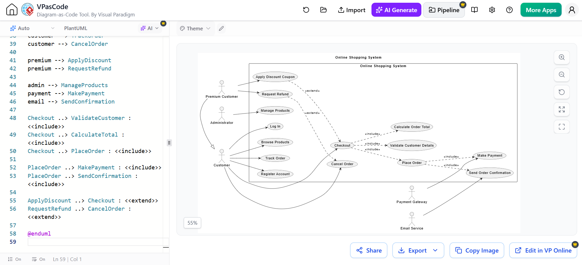
@startuml
title Online Shopping System

left to right direction

actor Customer as customer
actor "Premium Customer" as premium
actor Administrator as admin
actor "Payment Gateway" as payment
actor "Email Service" as email

premium -|> customer

rectangle "Online Shopping System" {
    usecase "Register Account" as Register
    usecase "Log In" as Login
    usecase "Browse Products" as Browse
    usecase "Checkout" as Checkout
    usecase "Place Order" as PlaceOrder
    usecase "Track Order" as TrackOrder
    usecase "Cancel Order" as CancelOrder

    usecase "Validate Customer Details" as ValidateCustomer
    usecase "Calculate Order Total" as CalculateTotal
    usecase "Make Payment" as MakePayment
    usecase "Send Order Confirmation" as SendConfirmation

    usecase "Apply Discount Coupon" as ApplyDiscount
    usecase "Request Refund" as RequestRefund

    usecase "Manage Products" as ManageProducts
}

customer --> Register
customer --> Login
customer --> Browse
customer --> Checkout
customer --> TrackOrder
customer --> CancelOrder

premium --> ApplyDiscount
premium --> RequestRefund

admin --> ManageProducts
payment --> MakePayment
email --> SendConfirmation

Checkout ..> ValidateCustomer : <<include>>
Checkout ..> CalculateTotal : <<include>>
Checkout ..> PlaceOrder : <<include>>

PlaceOrder ..> MakePayment : <<include>>
PlaceOrder ..> SendConfirmation : <<include>>

ApplyDiscount ..> Checkout : <<extend>>
RequestRefund ..> CancelOrder : <<extend>>

@enduml
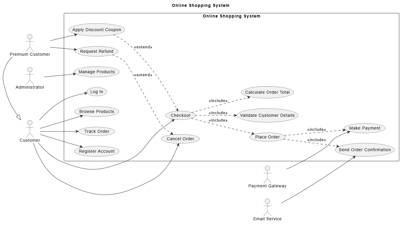
The same model can be refined in several ways:
-
Change layout direction with
left to right direction. -
Add notes to explain business rules.
-
Group use cases into packages.
-
Add styling with
skinparam. -
Rename aliases without changing visible labels.
-
Keep the diagram source under version control.
-
Regenerate the diagram whenever the model changes.
Visual modeling versus diagram-as-code
| Approach | Best suited for | Main advantage | Main limitation |
|---|---|---|---|
| Visual Paradigm UML | Interactive modeling and stakeholder workshops | Direct manipulation and visual review | Changes may be harder to compare as text |
| AI-assisted modeling | Drafting models from requirements | Quickly identifies candidate elements | Generated relationships require validation |
| VPasCode and PlantUML | Repeatable, text-based modeling | Easy to version, review, and regenerate | Requires familiarity with syntax |
| Combined workflow | Professional analysis and development | Combines speed, precision, and collaboration | Requires checking consistency across representations |
A practical combined workflow
A productive workflow is to use each tool for the task it handles best:
-
Capture requirements in natural language.
Describe users, goals, system scope, and business rules. -
Use AI to create an initial model.
Ask the AI to identify actors and use cases, then generate a first draft. -
Review the draft in Visual Paradigm UML.
Check whether the model accurately reflects the domain and whether the diagram is easy to understand. -
Export or rewrite the model in PlantUML.
Use aliases, consistent names, and explicit relationship syntax. -
Maintain the source in VPasCode or version control.
Store the.pumlfile with the project documentation or source code. -
Validate the UML semantics.
Pay particular attention toinclude,extend, and generalization direction. -
Publish the final diagram.
Export it as an image or document for requirements, architecture, design reviews, and project documentation.
Prompt for generating a PlantUML use case diagram
The following prompt can be used with an AI modeling assistant:
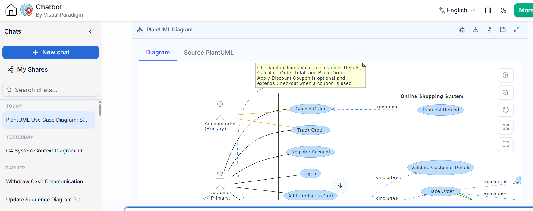
Generate a PlantUML use case diagram for an online shopping system.

Use a left-to-right layout and place all system use cases inside a
rectangle named "Online Shopping System".

Actors:
- Customer
- Premium Customer
- Administrator
- Payment Gateway
- Email Service

Customer use cases:
- Register Account
- Log In
- Browse Products
- Add Product to Cart
- Checkout
- Track Order
- Cancel Order

Checkout must include:
- Validate Customer Details
- Calculate Order Total
- Place Order

Place Order must include:
- Make Payment
- Send Order Confirmation

Optional behavior:
- Apply Discount Coupon extends Checkout
- Request Refund extends Cancel Order

Premium Customer is a specialization of Customer.

Use standard PlantUML syntax and include:
- Actor aliases
- Use-case aliases
- System boundary
- Actor associations
- <<include>> relationships
- <<extend>> relationships
- Actor generalization
- At least one explanatory note

Ensure that include arrows point from the base use case to the included use case,
and extend arrows point from the optional extending use case to the base use case.
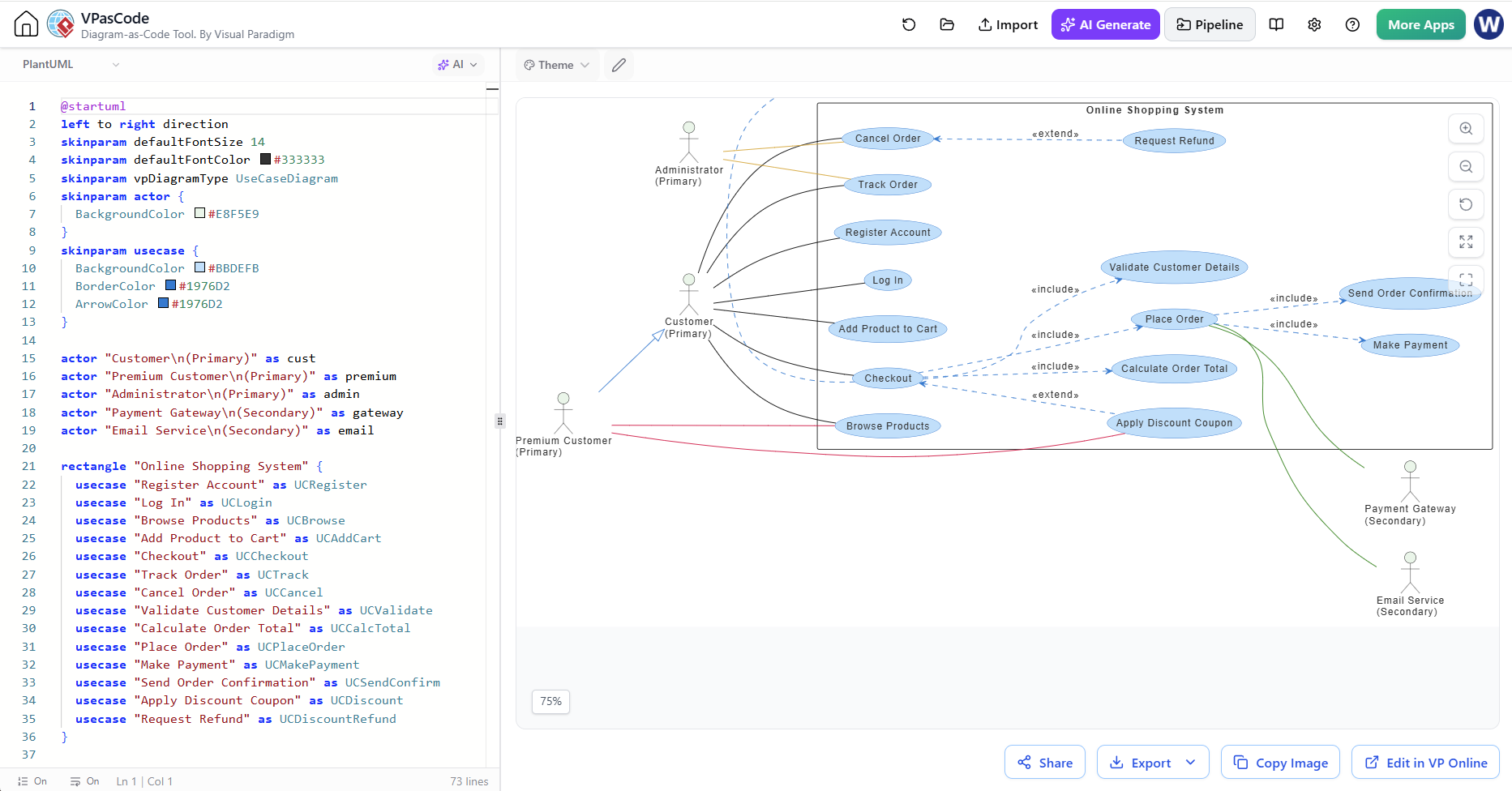
Key takeaway
Visual Paradigm UML is well suited to interactive modeling and review, AI can accelerate the transition from requirements to a first draft, and VPasCode with PlantUML provides a repeatable text-based workflow. Used together, they support the full modeling lifecycle: describe the requirements, generate a draft, validate the UML, refine the source, and publish a maintainable diagram.
Related posts:
 Comprehensive Guide: From Problem Statement to Class Diagram, ERD, and Database Modeling with Visual Paradigm
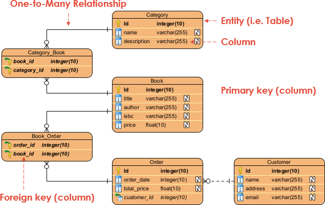 Visual Paradigm’s AI‑Powered ERD Generator
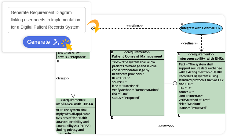 How Visual Paradigm’s AI Diagram Generation Turns Your Ideas into Professional UML & BPMN Diagrams in Seconds
 Why Teams Are Switching to Visual Paradigm: Powerful Modeling Meets Cutting-Edge AI