


Welcome to the definitive guide on using the Visual Paradigm AI Chatbot. This tool revolutionizes visual modeling by allowing you to generate, refine, and analyze professional UML, BPMN, ArchiMate, and C4 diagrams entirely through natural language conversation. Whether you are a software architect, a business analyst, or a student, this AI co-pilot eliminates the tedious “drag-and-drop” chore of manual diagramming.
1. Introduction to AI Chatbot Basics
The Visual Paradigm AI Chatbot is not just a text generator; it is a specialized engine trained on millions of validated visual modeling artifacts and industry standards (UML, SysML, ArchiMate). Unlike generic AI tools that may produce structurally invalid diagrams, this assistant enforces strict modeling rules, ensuring your output is ready for professional use.
Key Concepts
- Instant Diagram Generation: Transform plain text descriptions into fully structured, editable diagrams in seconds.
- Conversational Refinement: Treat your diagrams as living documents. You can evolve them through chat commands like “Add a retry loop” or “Change the relationship to composition.”
- Intelligent Analysis: Ask the AI to identify design flaws, single points of failure, or explain complex relationships within your model.
- Cross-Platform Integration: Diagrams generated in the web chat can be seamlessly imported into the Visual Paradigm Desktop app for advanced editing and version control.
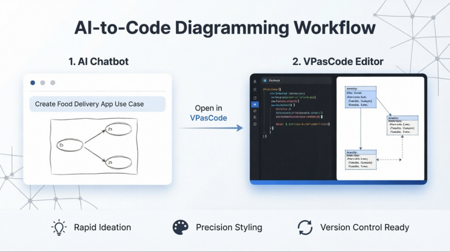
Diagram Example: AI-to-Code Workflow. The chatbot converts a natural language prompt into a structured diagram, which can then be viewed in the Visual Paradigm VPasCode editor for precise styling and code export.
2. Step-by-Step Guide: Getting Started
Follow this streamlined process to create your first diagram.
Step 1: Access the Chatbot
Navigate to the official AI Chatbot interface:
- URL: https://chat.visual-paradigm.com
- Action: Sign in with a free account to save your chats and export diagrams. No credit card is required for the basic trial.
Step 2: Start a New Conversation
- Click the + New Chat button in the sidebar.
- Name your chat (e.g., “E-Commerce Checkout Flow”) to keep your project organized.
Step 3: Describe and Generate
Type a clear, natural language prompt. The AI understands context and will generate the appropriate diagram type.
Prompt Example:
“Generate a UML sequence diagram for a user logging into a website. Include steps for entering credentials, server validation, and error handling for invalid passwords.”
What happens next:
- The AI renders a sequence diagram with lifelines (User, Login UI, Server, Database).
- It includes activation bars, message arrows, and an
altfragment for the branching logic (valid vs. invalid credentials).
Step 4: Refine with Natural Language
Don’t like the first version? Just chat with it.
- Add Logic: “Add a two-factor authentication step after password validation.”
- Modify: “Change the error message to display ‘Account Locked’ after three failed attempts.”
- Style: “Make the layout more compact for a presentation slide.”
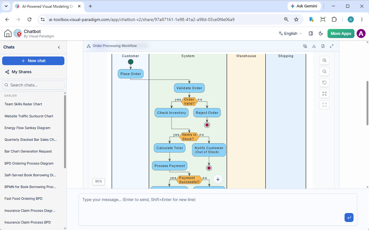
Diagram Example: A BPMN “Order Processing Workflow” showing swimlanes for Customer, System, Warehouse, and Shipping, illustrating how the AI handles complex process flows.
3. Key Concepts and Examples with PlantUML
3.1 Key Concept: Sequence Diagrams (Interaction Flows)
Sequence diagrams visualize the order of messages between objects over time. The AI Chatbot excels at creating these with complex logic like loops and conditional branches.
Prompt Example:
“Create a sequence diagram for a microservice checkout process where the Cart Service calls the Inventory System and Payment Gateway. Handle the case where stock is low.”
Generated PlantUML Example:
@startuml
participant "Customer" as C
participant "Frontend App" as F
participant "Cart Service" as CS
participant "Inventory System" as IS
participant "Payment Gateway" as PG

C -> F: View Cart
F -> CS: GetCartData
CS -> IS: CheckStock("Item1")
IS --|> CS: StockAvailable? Yes/No

alt Stock Available
    CS -> PG: ProcessPayment
    PG --|> CS: Success
    CS -> IS: ReserveStock
    CS --> F: OrderConfirmed
else Stock Low
    CS --> F: OutOfStockError
end
@enduml
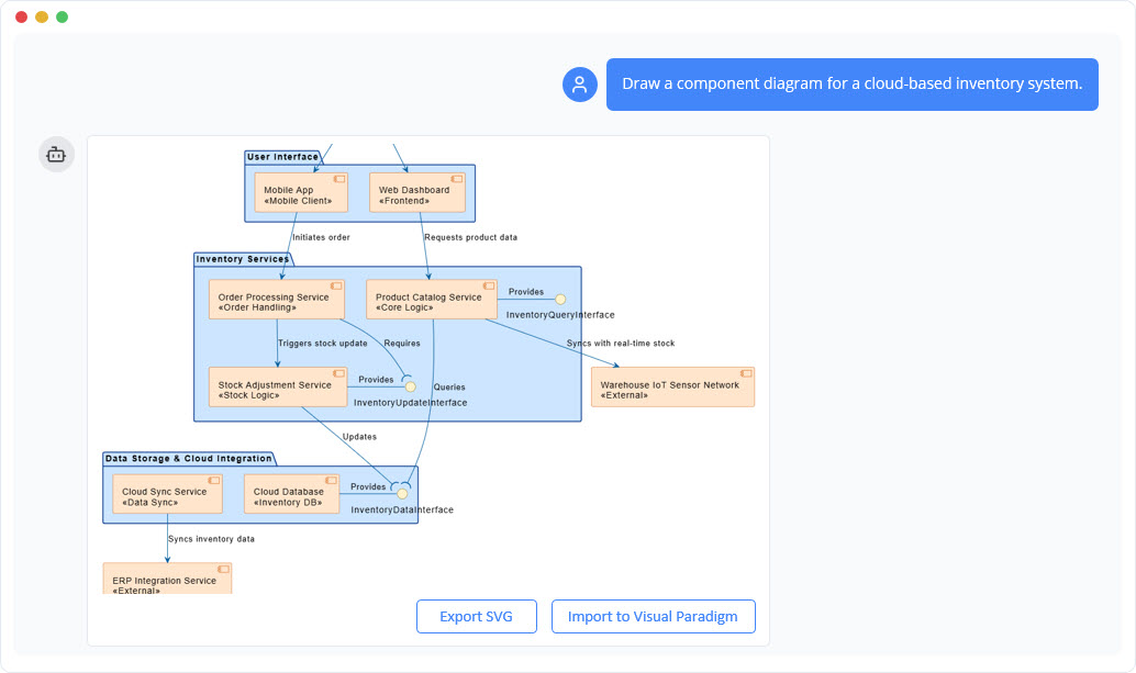
Diagram Example: A layered component diagram showing User Interface, Inventory Services, and Data Storage layers, demonstrating how the AI handles architectural modeling.
3.2 Key Concept: Class Diagrams (Structural Design)
Class diagrams define the static structure of a system, including classes, attributes, and relationships.
Prompt Example:
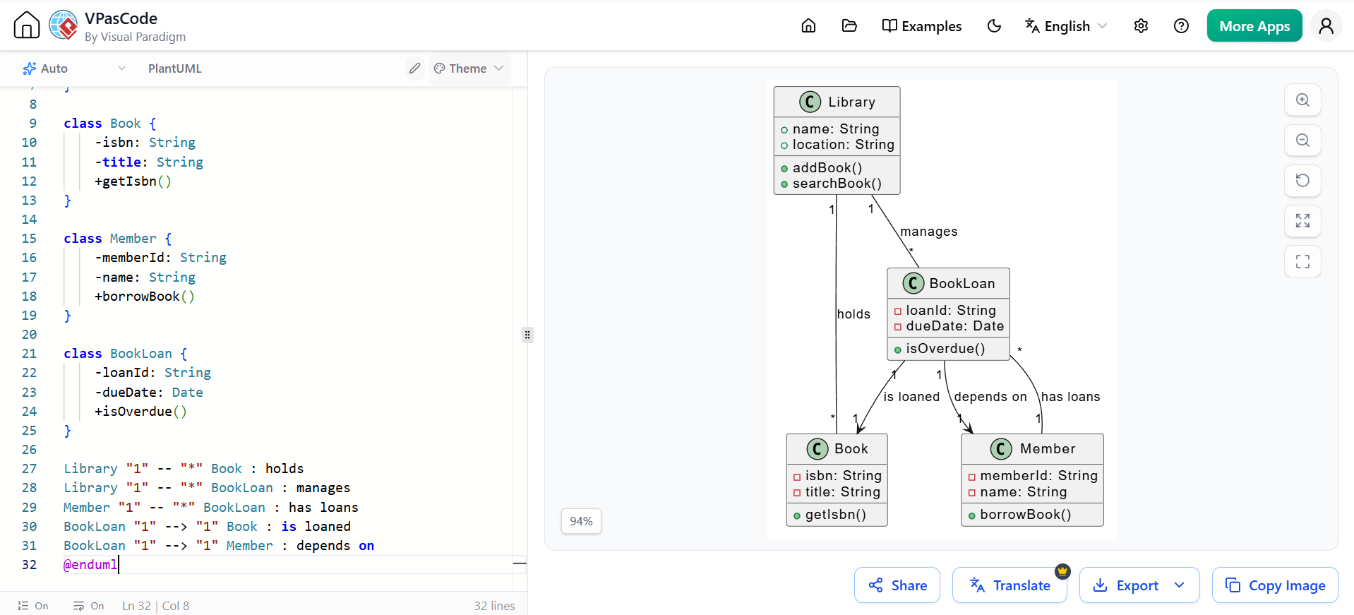
“Generate a UML class diagram for a Library Management System. Include classes for Book, Member, and BookLoan. Define relationships like ‘Member borrows Book’ and ‘Library manages BookLoan’.”
Generated PlantUML Example:
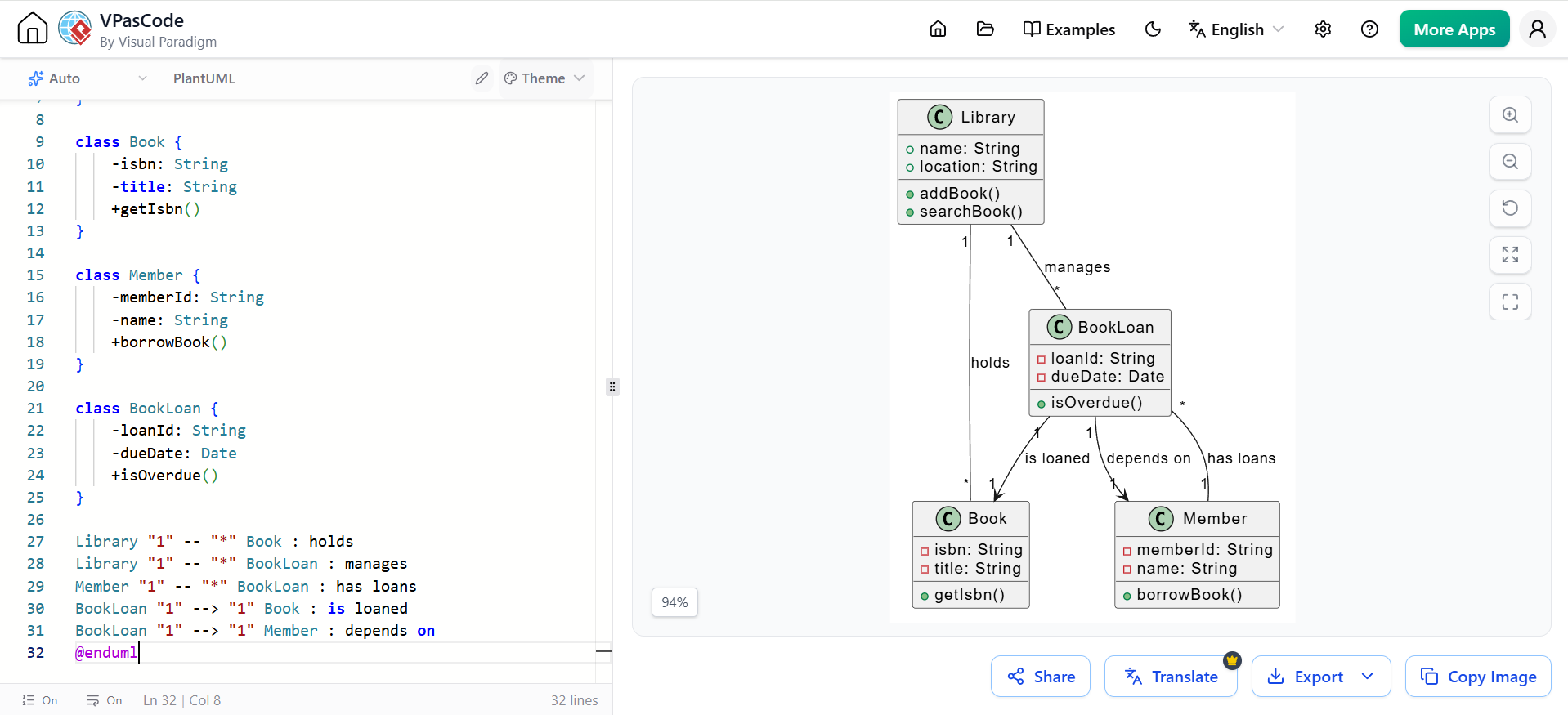
@startuml
class Library {
    +name: String
    +location: String
    +addBook()
    +searchBook()
}

class Book {
    -isbn: String
    -title: String
    +getIsbn()
}

class Member {
    -memberId: String
    -name: String
    +borrowBook()
}

class BookLoan {
    -loanId: String
    -dueDate: Date
    +isOverdue()
}

Library "1" -- "*" Book : holds
Library "1" -- "*" BookLoan : manages
Member "1" -- "*" BookLoan : has loans
BookLoan "1" --> "1" Book : is loaned
BookLoan "1" --> "1" Member : depends on
@enduml
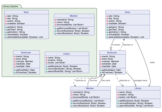
Diagram Example: A UML Class Diagram for a Library System showing 6 classes with attributes (private fields) and methods (public operations), plus relationships between them.
3.3 Key Concept: Use Case Diagrams (Functional Requirements)
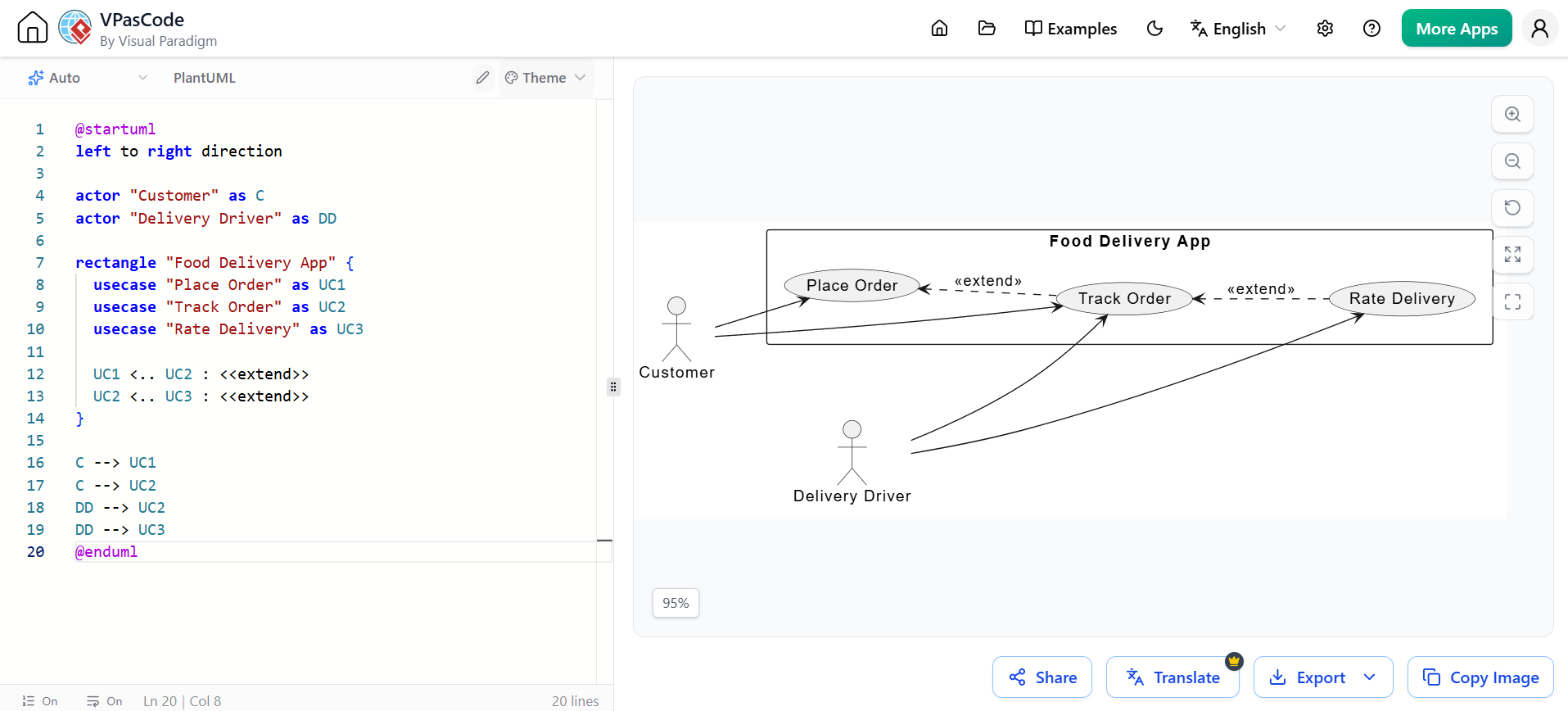
Use case diagrams capture the functional requirements of a system from a user’s perspective.
Prompt Example:
“Create a use case diagram for a Food Delivery App. Actors: Customer, Delivery Driver, Restaurant Manager. Use cases: Place Order, Track Order, Rate Delivery, Manage Menu.”
Generated PlantUML Example:
@startuml
usecase "Place Order" as UC1
usecase "Track Order" as UC2
usecase "Rate Delivery" as UC3

actor "Customer" as C
actor "Delivery Driver" as DD

C --> UC1
DD --> UC2
DD --> UC3

package "Food Delivery App" {
  UC1 -- UC2 : extends
  UC2 -- UC3 : extends
}
@enduml
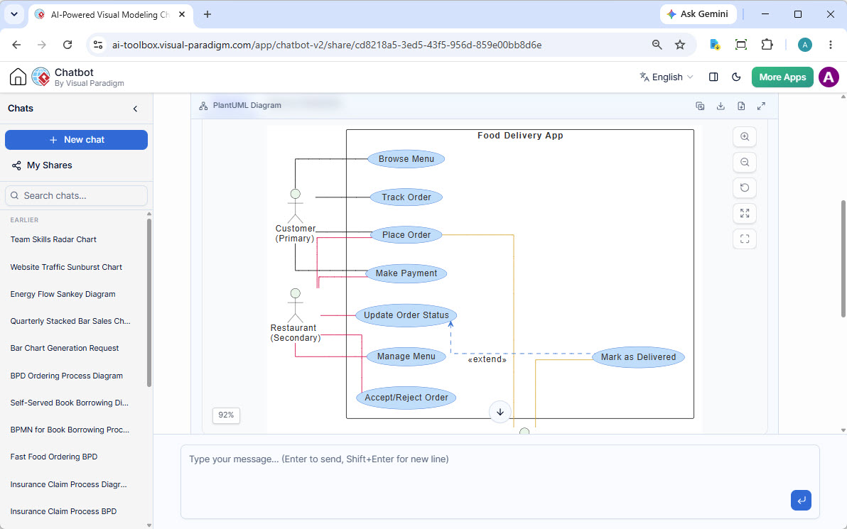
Diagram Example: A use case diagram for a “Food Delivery App” with Customer and Restaurant actors, showing core functions and extension relationships.
3.4 Key Concept: State Machine Diagrams (Lifecycle Management)
State diagrams model the dynamic behavior of an object, showing how it reacts to events over time.
Prompt Example:
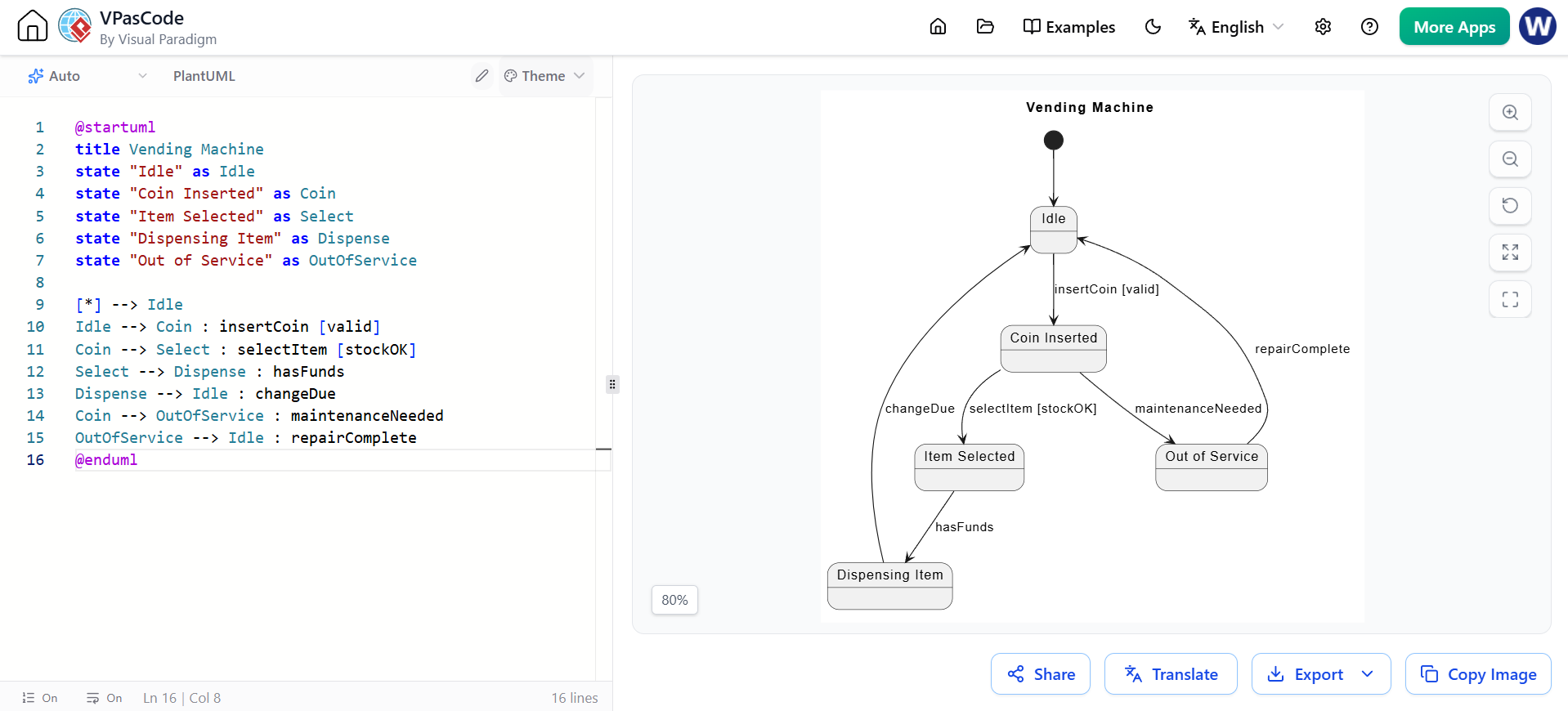
“Generate a state diagram for a Vending Machine. States: Idle, Coin Inserted, Item Selected, Dispensing, Out of Service.”
Generated PlantUML Example:
@startuml
state diagram Vending Machine
  state "Idle" as Idle
  state "Coin Inserted" as Coin
  state "Item Selected" as Select
  state "Dispensing Item" as Dispense
  state "Out of Service" as OutOfService

  [*] --> Idle
  Idle --> Coin : insertCoin [valid]
  Coin --> Select : selectItem [stockOK]
  Select --> Dispense : hasFunds
  Dispense --> Idle : changeDue
  Coin --> OutOfService : maintenanceNeeded
  OutOfService --> Idle : repairComplete
@enduml

Diagram Example: A PlantUML state diagram for a vending machine showing states like Idle, Coin Inserted, and transitions triggered by events like ‘insertCoin’.
3.5 Key Concept: Activity Diagrams (Workflow and Process)
Activity diagrams describe the flow of control from one activity to another, often used for business processes or algorithms.
Prompt Example:
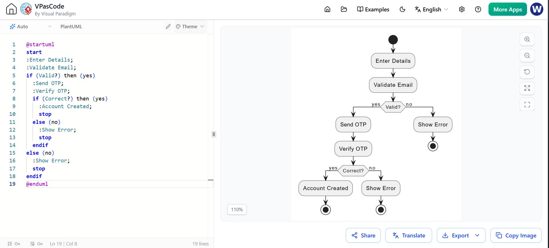
“Create an activity diagram for a User Registration Process. Include steps: Enter Details, Validate Email, Send OTP, Verify OTP, Account Created.”
Generated PlantUML Example:
@startuml
start
:Enter Details;
:Validate Email;
if (Valid?) then (yes)
  :Send OTP;
  :Verify OTP;
  if (Correct?) then (yes)
    :Account Created;
    stop
  else (no)
    :Show Error;
    stop
  endif
else (no)
  :Show Error;
  stop
endif
@enduml
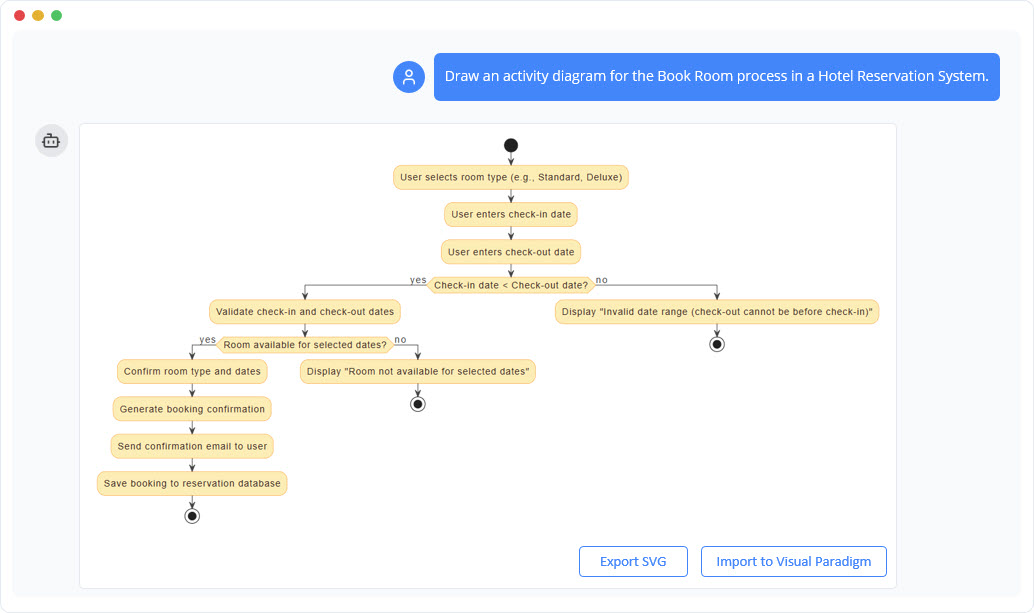
Diagram Example: A flowchart showing a decision-making workflow with loops, branching paths, and error handling for a retry mechanism.
3.6 Key Concept: Conversational Refinement (Iterative Design)
The AI Chatbot’s unique power lies in its ability to update diagrams via conversation without starting over.
Scenario: You have a sequence diagram, but now you need to add a “Circuit Breaker” pattern for resilience.
Prompt: “Insert a Circuit Breaker component between the Client and the Payment Gateway. If the gateway fails three times, trigger a fallback service.”
Result: The AI automatically adds the new lifeline, the retry logic alt fragment, and the fallback message flow.
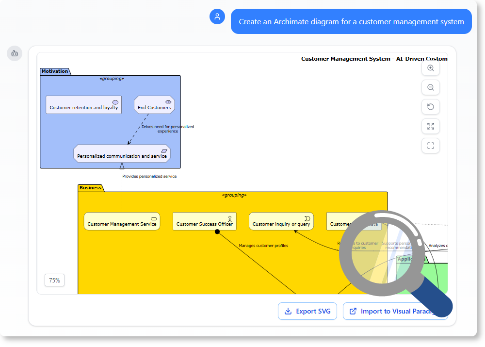
Diagram Example: A comparison of architecture diagrams showing how the AI handles standard UML notation and logical consistency.
4. Advanced Features: Integration and Analysis
4.1 Desktop Integration
Diagram generation starts in the cloud, but for professional work, you can import them directly into the Visual Paradigm Desktop application. This allows for:
- Round-Trip Engineering: Sync changes between web and desktop.
- Code Generation: Export Java, C#, or SQL code directly from your UML models.
- Offline Modeling: Work without internet once the project is synced.
4.2 Intelligent Analysis
Ask the AI to audit your diagrams for best practices.
- Prompt: “Does this class diagram violate the Law of Demeter?”
- Prompt: “Identify all single points of failure in this architecture.”
- Prompt: “Generate a project summary listing all use cases and their actors.”
5. Reference List: AI Chatbot Resources
- A Beginner’s Guide to AI-Powered UML with Visual Paradigm
- The AI Chatbot as an Architectural Co-pilot
- Conversational Sequence Diagrams
- AI Chatbot for Visual Modeling
- Visual Paradigm AI Toolbox – Chatbot App
- How to Turn Requirements into Diagrams with an AI Chatbot
- Visual Paradigm Pipeline: The Bridge for AI Modeling
- Cascading Updates Demo Video
This post is also available in Deutsch, Español, فارسی, Français, English, Bahasa Indonesia, 日本語, Polski, Portuguese, Ру́сский, Việt Nam, 简体中文 and 繁體中文.