


Introduction to Block Definition Diagrams
The Block Definition Diagram (BDD) is the most widely-used diagram for modeling the static structure of a system in SysML. Derived from the UML Class Diagram, it serves as a foundational tool for systems engineers to declare Blocks and define their relationships.
Key Characteristics:
-
Compositional Relationships: Define how blocks contain or reference other blocks
-
Logical Relationships: Express associations and dependencies between system elements
-
Generalization/Inheritance: Model hierarchical classifications and specialization
-
Instance Modeling: Classes and Objects from UML become Blocks and their instances
-
Physical Connections: Parts can be tied together by Connectors; physical connections between Part instances are Links
-
Association Blocks: Connectors can be typed by associations defined through Association Blocks
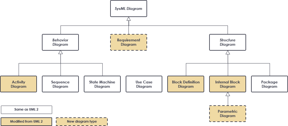
Figure 1: SysML diagram types overview showing the position of Block Definition Diagrams within the SysML framework
You can display various kinds of model elements and relationships on a BDD to express comprehensive information about a system’s structure. This flexibility makes BDDs essential for both high-level architectural design and detailed component specification.
Structure Diagrams: BDD vs IBD vs Package Diagram
Understanding the distinctions between SysML’s structural diagrams is critical for effective system modeling. The three primary structural representations serve complementary purposes:
Block Definition Diagram (BDD)
-
Origin: Modification of the UML Class Diagram
-
Primary Purpose: Define system elements and their static relationships
-
Key Relationships Supported:
-
Composition (whole-part relationships)
-
Reference associations
-
Generalization/Inheritance hierarchies
-
Dependencies and realizations
-
Internal Block Diagram (IBD)
-
Origin: Modified from the UML Composite Structure Diagram
-
Primary Purpose: Show how system elements are used and interact
-
Key Features:
-
Emphasizes interactions among elements (typically Parts within a Block)
-
Models various kinds of Interfaces and Flows
-
Details port connections, item flows, and communication paths
-
Visualizes runtime behavior and data exchange
-
Package Diagram
-
Origin: Directly inherited from UML
-
Primary Purpose: Organize the model into manageable, logical groups
-
Key Benefits:
-
Supports modular model development
-
Enables team collaboration through model partitioning
-
Facilitates reuse of model elements across projects
-
Provides namespace management for large-scale systems
-
Best Practice: Use BDDs to define what the system is composed of, IBDs to show how components interact, and Package Diagrams to organize where elements reside in your model repository.
When to Use Block Definition Diagrams
Block Definition Diagrams are versatile tools applicable throughout the system development lifecycle. Consider using a BDD when you need to:
✅ Design Phase Applications
-
Define System Architecture: Establish the high-level structure of your system
-
Specify Component Interfaces: Document ports, operations, and properties of blocks
-
Model Domain Concepts: Capture business entities and their relationships
-
Support Reusability: Create extensible system structures that accommodate evolving stakeholder needs
✅ Analysis & Validation Applications
-
Trace Requirements: Link requirement elements to structural blocks
-
Perform Impact Analysis: Understand how changes propagate through the system hierarchy
-
Validate Completeness: Ensure all necessary components and relationships are modeled
-
Support Verification: Provide structural context for test case development
✅ Communication Applications
-
Stakeholder Alignment: Visualize system structure for non-technical audiences
-
Team Coordination: Provide a shared reference for distributed development teams
-
Documentation Generation: Serve as the foundation for automated technical documentation
Pro Tip: Adopt design techniques for creating extensible system structures early in your project. This practice significantly reduces the time and cost required to adapt your design as stakeholder needs evolve.
From System Context to Component Structure
A powerful approach to system modeling begins with establishing context before diving into component details. This progression ensures alignment between the system and its environment.
System Context Diagram (User-Defined IBD Usage)
Modelers can leverage a user-defined usage of an Internal Block Diagram—often called a System Context Diagram—to depict top-level entities in the overall enterprise and their relationships.
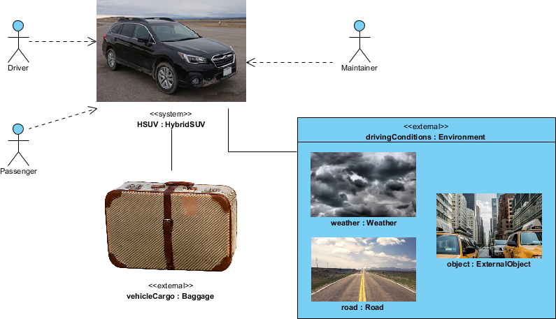
Figure 2: System Context Diagram showing the system of interest and its external environment
Key Modeling Techniques for Context Diagrams:
| Technique | Description | Benefit |
|---|---|---|
| «system» / «external» Stereotypes | User-defined stereotypes (not in SysML spec) to identify the system boundary | Clarifies scope and environmental interfaces |
| Graphical Icons | Custom icons for model elements | Enhances visual comprehension and stakeholder engagement |
| Spatial Layout | Strategic positioning of entities on the diagram | Conveys contextual relationships beyond formal semantics |
| Background Context | Inclusion of maps, network diagrams, or other reference imagery | Provides real-world grounding for abstract models |
| Abstract Associations | High-level relationships among classes | Establishes conceptual links to be refined in subsequent diagrams |
Refinement Workflow:
-
Initial Phase: Entities are conceptual and relationships are abstract
-
Development Phase: Use Case Diagrams and BDDs refine entities and relationships
-
Detailed Design: Component structures are fully specified with ports, interfaces, and flows
-
Implementation: Model elements map directly to code, configuration, or hardware specifications
Note: The relationships depicted in the System Context Diagram are reflected in downstream diagrams such as the Automotive Domain Model Block Definition Diagram, ensuring traceability from concept to implementation.
High-level Block Definition Diagram
Once the system context is established, the next step is to define the conceptual structure using a high-level Block Definition Diagram.
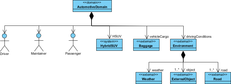
Figure 3: High-level Block Definition Diagram defining concepts from the context diagram
Characteristics of High-Level BDDs:
-
Abstract Blocks: Represent major system domains or subsystems without implementation details
-
Conceptual Relationships: Focus on logical associations rather than physical connections
-
Stakeholder-Oriented: Designed for communication with architects, managers, and domain experts
-
Foundation for Refinement: Serves as the template for more detailed component diagrams
Modeling Best Practices:
// Example: High-level automotive system structure
block Vehicle {
    + powertrain : PowerSubsystem
    + chassis : ChassisSubsystem
    + electronics : ElectronicsSubsystem
}

block PowerSubsystem {
    + engine : Engine
    + transmission : Transmission
    + energyStorage : EnergyStorage
}

// Generalization example
block EnergyStorage <|-- ElectricBattery
block EnergyStorage <|-- FuelTank
Key Insight: High-level BDDs should balance completeness with simplicity. Include enough detail to guide downstream development, but avoid premature commitment to implementation choices.
Block Definition Diagram – Hybrid SUV Example
Moving from abstract concepts to concrete implementation, lower-level BDDs define the detailed component structure of specific system elements.
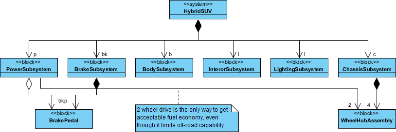
Figure 4: Detailed Block Definition Diagram for HybridSUV PowerSubsystem
Key Modeling Observations:
Composition vs. Reference Relationships
-
Contained Elements: Components owned by the parent block (solid diamond composition)
-
Referenced Elements: Components used by but not contained in the parent block (open arrow reference)
Important Note: In the Hybrid SUV example,
BrakePedalandWheelHubAssemblyare used by but not contained in thePowerSubsystemblock. This distinction is critical for accurate lifecycle management and interface definition.
Detailed Component Specification
A lower-level BDD typically includes:
-
Properties: Attributes with types, multiplicities, and default values
-
Operations: Behavioral interfaces with parameters and return types
-
Ports: Interaction points for external communication (flow ports, standard ports)
-
Constraints: Parametric relationships governing system behavior
-
Values: Quantifiable properties with units and bounds
Example Structure Snippet:
block PowerSubsystem {
    // Composition: owned parts
    + engine : HybridEngine [1]
    + electricMotor : ElectricMotor [1]
    + battery : HighVoltageBattery [1]

    // Reference: external dependencies
    + brakePedal : BrakePedal [0..1]
    + wheelAssembly : WheelHubAssembly [4]

    // Operations
    + calculatePowerDemand() : PowerValue
    + manageEnergyFlow(source: EnergySource, target: EnergySink)

    // Ports
    + powerOutput : FlowPort <<MechanicalPower>>
    + controlInterface : StandardPort <<CAN-Bus>>
}
Design Principle: Clearly distinguish between composition (ownership) and reference (usage) relationships. This affects memory management, initialization sequences, and failure propagation analysis.
AI-Powered SysML Modeling with Visual Paradigm
Visual Paradigm enhances traditional SysML modeling with AI-powered generative capabilities, enabling engineers to automate diagram creation and refinement using natural language prompts.
Core AI SysML Diagram Support
The AI engine interprets technical descriptions and architectural intent to generate foundational SysML diagrams:
🎯 Requirement Diagrams
-
Instantly generates hierarchical requirement structures
-
Automatically assigns unique IDs to requirement blocks
-
Establishes relationships:
<<deriveReqt>>,<<satisfy>>,<<verify>> -
Converts plain text specifications into traceable requirement models
🧱 Block Definition Diagrams (BDD)
-
Automates creation of system hierarchies and classifications
-
Example prompt: “Create a BDD for a smart TV with video streaming, audio processing, and network connectivity modules”
-
Supports iterative refinement: “Add a voice control interface to the SmartTV block”
🔗 Internal Block Diagrams (IBD)
-
Produces detailed internal structures with ports, connectors, and item flows
-
AI serves as a “co-pilot” to ensure structurally compliant wiring
-
Validates interface compatibility and flow consistency
Key AI Features for Systems Engineering
| Feature | Capability | Benefit |
|---|---|---|
| Conversational Editing | Refine diagrams via chat: “Add payment gateway”, “Rename blocks”, “Refactor relationships” | Reduces manual editing; accelerates iteration |
| Intelligent Analysis | Explain diagrams, suggest improvements, identify mismatches (e.g., incompatible port types) | Improves model quality; prevents integration errors |
| Automated Documentation | Generate reports, summaries, and professional documentation on-demand | Saves time; ensures consistency across deliverables |
| Traceability & Compliance | Automatically establish auditable traces from stakeholder needs to design components and verification tests | Supports regulatory compliance; simplifies impact analysis |
| Seamless Integration | Import AI-generated diagrams from VP Online Chatbot into Visual Paradigm Desktop | Combines AI speed with desktop power for versioning and collaboration |
Getting Started with AI-Powered Modeling:
-
Access the Visual Paradigm AI Chatbot
-
Describe your system or component in natural language
-
Specify the diagram type (BDD, IBD, Requirement)
-
Review and refine the AI-generated output
-
Export to desktop environment for advanced editing and team collaboration
Pro Tip: Start with high-level prompts to establish architecture, then use iterative refinement prompts to add detail. This approach mirrors traditional modeling workflows while leveraging AI efficiency.
References
Primary Guide Sections
-
SysML: Modeling Element Structure with Block Definition Diagram – Introduction: Foundational overview of Block Definition Diagrams, their UML heritage, and core modeling capabilities for static system structure.
-
Structure Diagrams: Block Definition vs Internal Block Structure vs Package Diagram: Comparative analysis of SysML’s three primary structural diagram types and their complementary roles in system modeling.
-
When to Use Block Definition Diagram?: Practical guidance on applying BDDs throughout the system development lifecycle for design, analysis, and communication purposes.
-
From System Context to Component Structure: Methodology for progressing from high-level context diagrams to detailed component specifications using user-defined stereotypes and refinement workflows.
-
High-level Block Definition Diagram: Techniques for creating abstract, stakeholder-oriented BDDs that establish architectural foundations for downstream development.
-
Block Definition Diagram – Hybrid SUV: Detailed example demonstrating composition vs. reference relationships and component specification in a real-world automotive system.
Visual Paradigm AI & Tooling Resources
-
Visual Paradigm AI Chatbot Features: Overview of AI-powered conversational modeling capabilities for SysML, UML, and other diagram types with cloud-to-desktop integration.
-
AI-Powered Block Definition Diagram Generation: Interactive tool for generating BDDs from natural language prompts with iterative refinement support.
-
AI Diagram Generation Platform: Comprehensive suite of AI tools for automating creation of multiple diagram types across systems and software engineering domains.
-
AI Diagram Generator Updates: DFD & ERD Support: Release notes detailing expanded AI capabilities for Data Flow Diagrams and Entity Relationship Diagrams alongside SysML support.
-
SysML Diagram Tool Features: Full-featured desktop environment for professional SysML modeling with support for all nine SysML diagram types and team collaboration capabilities.
-
SysML Tutorial: Block Definition Diagrams: Video walkthrough demonstrating BDD creation, relationship modeling, and best practices in Visual Paradigm.
-
AI-Powered SysML Requirement Diagram Guide: Step-by-step tutorial for using AI to generate, refine, and trace requirement models with automatic relationship establishment.
-
Article: AI-Powered SysML Requirement Diagram Tool: Case study and technical overview of applying AI to requirements engineering workflows with traceability automation.
-
SysML Internal Block Diagram Tutorial: Video demonstration of IBD creation, port configuration, and item flow modeling for detailed system architecture.
-
Advanced SysML Modeling Techniques: Expert-level tutorial covering parametric diagrams, allocation relationships, and model validation strategies.
-
AI-Powered Internal Block Diagram Guide: Comprehensive documentation for using AI to generate and refine IBDs with automatic port typing and flow validation.
-
UML Diagram Generation with AI (Traditional Chinese): Localized guide for AI-assisted UML modeling, demonstrating cross-diagram type applicability of the AI engine.
-
Case Study: Enhancing System Modeling Efficiency with AI Chatbot: Real-world implementation story showcasing productivity gains, quality improvements, and ROI from AI-powered modeling adoption.
Final Recommendation: Block Definition Diagrams form the structural backbone of SysML models. By combining traditional modeling discipline with AI-powered automation, systems engineers can achieve both rigor and agility—defining clear architectures while rapidly adapting to evolving requirements. Start with context, refine through layers of abstraction, and leverage AI tools to accelerate iteration without sacrificing precision.
This post is also available in Deutsch, Español, فارسی, Français, English, Bahasa Indonesia, 日本語, Polski, Portuguese, Ру́сский, Việt Nam, 简体中文 and 繁體中文.