


Introduction
Visual Paradigm provides a comprehensive suite for Systems Modeling Language (SysML), recently enhanced with AI-powered generative modeling that automates the creation of complex system diagrams from natural language descriptions. This guide explores the full capabilities of Visual Paradigm’s SysML tools, from core diagram types to advanced AI-driven features that accelerate systems engineering workflows.

Core SysML Diagram Types
Visual Paradigm supports all nine standard SysML diagram types, organized by their modeling focus: structural, behavioral, and requirements.
Requirement Diagram
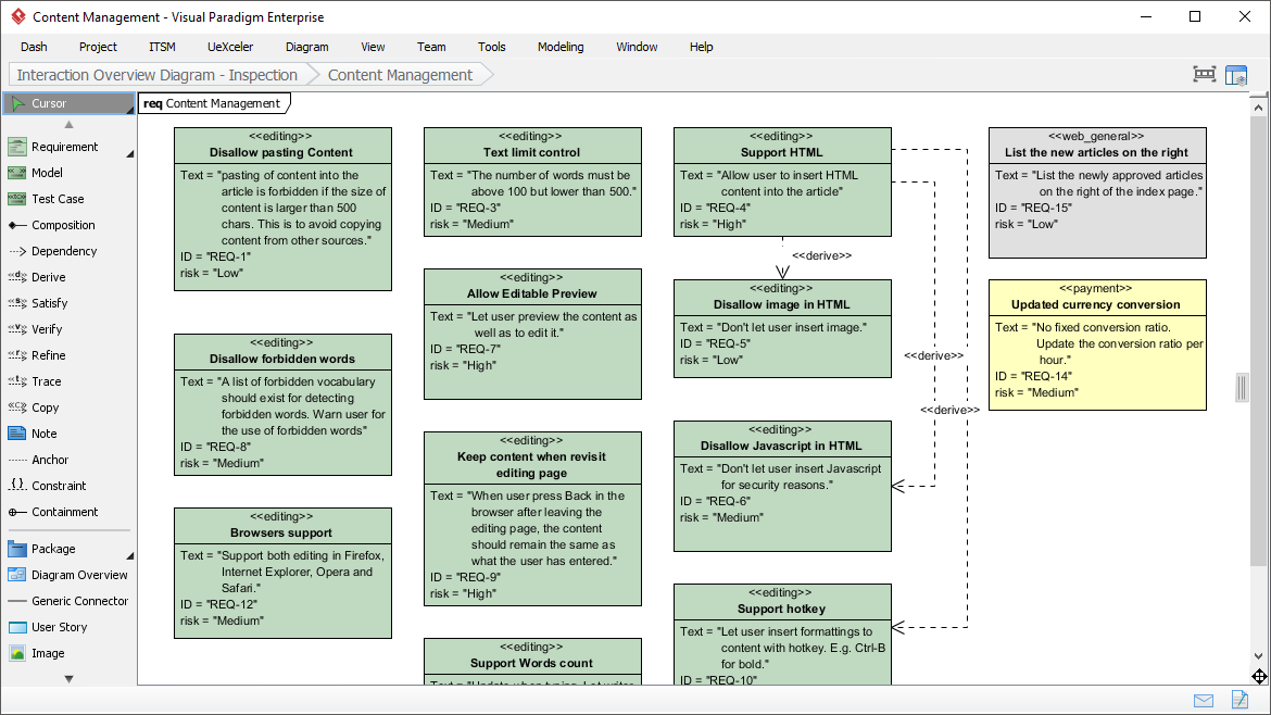
Effective identification and management of requirements can lead your project to success. The SysML tool features a SysML requirement diagram tool that provides a visual approach in representing and managing system requirements. In a requirement diagram, requirements are shown as blocks, with connectors in between, illustrating the derivation, dependency and grouping of requirements. The requirement diagram tool allows you to define your own requirement types, with user-defined properties and appearance, and to produce a list of requirement to Excel for external manipulation. Import the file back for updating.
Block Definition Diagram
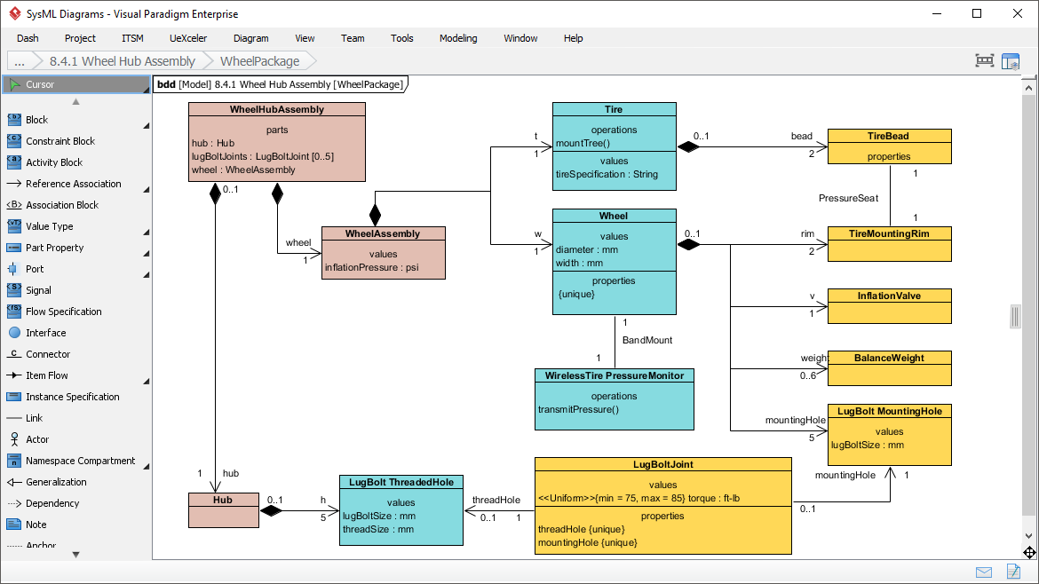
Visualize your system hierarchy. Define the system/component classifications in blocks to get a better picture of interconnections between these system components.
Internal Block Diagram
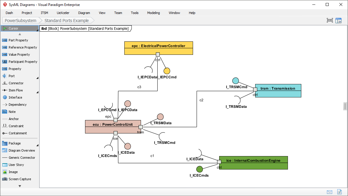
Take a closer look at your system design. Describe the internal structure of a system in terms of its parts, ports, and connectors.
Parametric Diagram
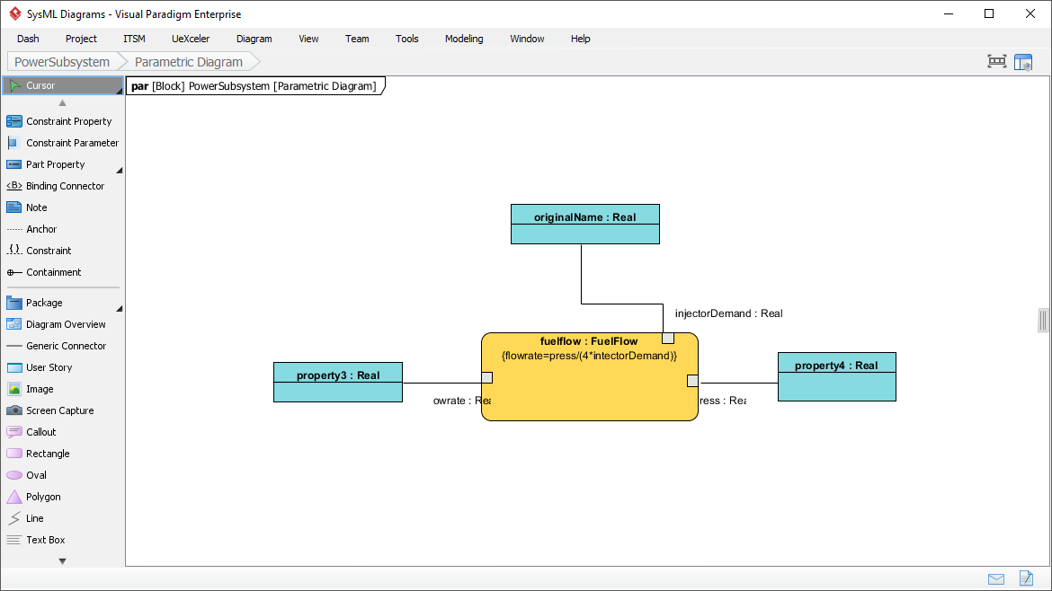
Parametric Diagram is a restricted form of internal block diagram that shows only the use of constraint blocks along with the properties they constrain within a context. Parametric diagram is used to support engineering analysis, such as performance, reliability, and mass properties analysis.
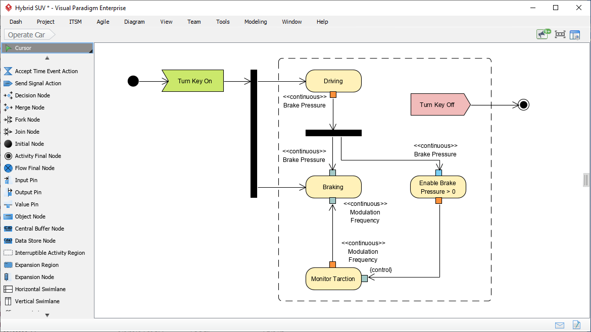
Activity Diagram
An activity diagram is used to specify a behavior, with a focus on the flow of control and the transformation of inputs into outputs through a sequence of actions. It is commonly used as an analysis tool to understand and express the desired behavior of a features, use case, or even the entire system. For example, an activity diagram is often be used to elaborate a number of possible use case scenarios, and that establish the traceability between a feature (use case model) and behavior model (activity diagram).
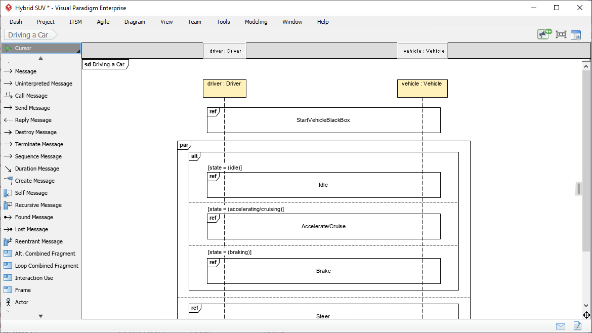
Sequence Diagram
A sequence diagram is used to specify a behavior, with a focus on how the parts of a block interact with one another via operation calls and asynchronous signals. Sequence diagrams are commonly used as a detailed design tool to precisely specify a behavior as an input to the development stage of the life cycle. For example, a sequence diagram is often be used to show a particular example of operation of a System, in the same way as movie-makers may draw up a storyboard. A storyboard shows the sequence of events in a film before it is made.
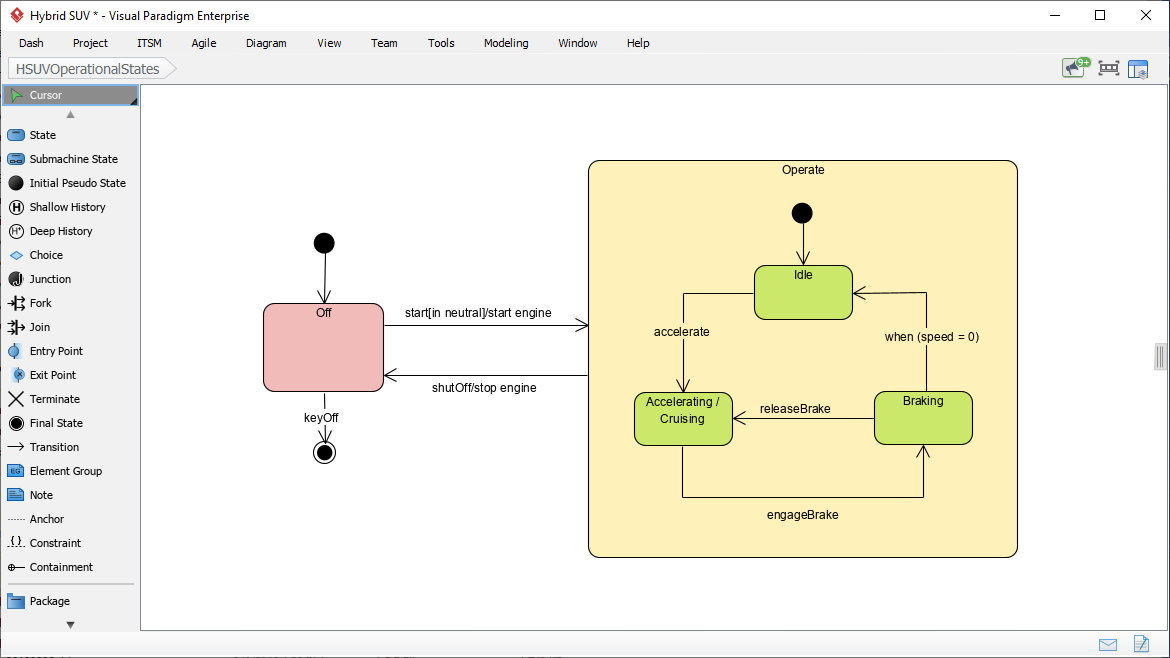
State Machine Diagram
A State Machine diagram shows system behavior as sequences of states that a component or interaction experience in response to events. A State represents a significant condition in the life of a Block. For example, it is often used to describe how a block transitions from one state to another and defines what logical behavior (Activities/Actions owned by the Block) are performed when entering or exiting a State. State machines are useful for system design and simulation/code generation.
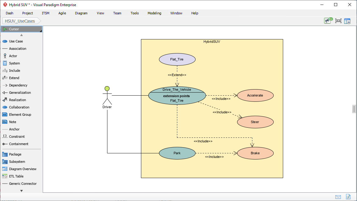
Use Case Diagram
A Use Case diagram shows system functional requirements as transactions that are meaningful to system users. It is a black-box view of the services that a system performs in collaboration with its actors. Useful for specifying functional requirements.
Package Diagram
A package diagram is useful for displaying the way a model is organized in the form of a package containment hierarchy. It shows how a model is organized into Packages, Views and Viewpoints. A package diagram may also show the model elements that packages contain and the dependencies between packages and their contained model elements. It is useful for model management.
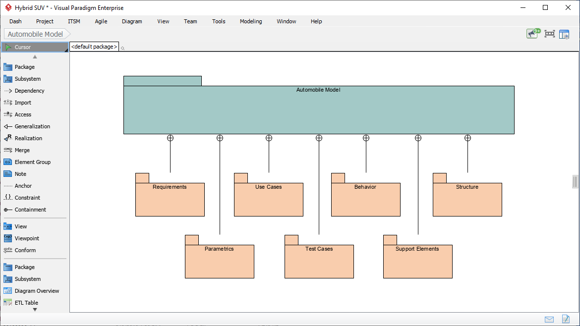
Diagram Categories Overview
| Category | Diagram Types | Primary Purpose |
|---|---|---|
| Structural | Block Definition (BDD), Internal Block (IBD), Package, Parametric | Model system hierarchy, internal connections, organization, and quantitative constraints |
| Behavioral | Activity, Sequence, State Machine, Use Case | Model processes, interactions over time, state transitions, and functional requirements |
| Requirements | Requirement Diagram | Visualize textual requirements and their traceability relationships |
Precision Meets Automation: AI-Powered SysML Internal Block Diagram Generation
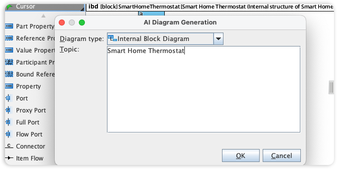
Visual Paradigm’s SysML tools are the benchmark for systems engineering, providing the rigorous framework needed to model internal system structures and data flows. We are now accelerating the engineering lifecycle by integrating Internal Block Diagram (IBD) support into our AI Diagram Generator, simplifying how you visualize the connections within complex system blocks.
This capability allows you to instantly produce detailed IBDs from technical descriptions, bypassing the manual effort of defining ports, connectors, and item flows. Simply describe your system’s internal parts and their interactions, and the AI automatically generates a structurally compliant SysML diagram. This allows your team to focus on system integrity and architectural validation rather than the intricacies of manual modeling.
AI-Driven SysML Features
The AI Diagram Generator acts as a “co-pilot” for systems engineering, allowing teams to bypass manual drawing for several key SysML types:
✦ Requirement Diagram Generation
-
Converts technical documents or plain text into structured requirement models
-
Automatically defines requirement IDs, text descriptions, and establishes relationships like
<<deriveReqt>>,<<satisfy>>, and<<verify>>
✦ Internal Block Diagram (IBD) Automation
-
Instantly produces detailed IBDs from structural descriptions
-
Automatically defines internal parts, ports, and connectors while maintaining structural compliance without manual placement
✦ Block Definition Diagram (BDD) Support
-
AI can generate BDDs for complex systems (e.g., Smart TV or Automotive systems)
-
Identifies and adds relevant modules or functions based on user prompts
✦ Traceability & Analysis
-
AI assistants can analyze models to suggest likely traceability links
-
Perform impact analysis, identifying which components are affected if a specific requirement changes
Advanced Modeling Capabilities
🔹 MBSE Integration
Facilitates Model-Based Systems Engineering (MBSE) by integrating requirements, structure, and behavior into a single cohesive model, enabling end-to-end traceability and consistency.
🔹 Flexible Allocation Tables
Provides specialized tables for functional, structural, and requirement allocations, which are more robust than standard UML options—supporting complex allocation matrices essential for systems engineering.
🔹 Simulation Support
Parametric diagrams can be used to mathematically constrain blocks, enabling system performance simulations for reliability, mass properties, and other engineering analyses.
🔹 Collaboration & Sync
Diagrams are fully editable after AI generation and can be synchronized across different views to ensure architectural consistency. Changes propagate automatically, reducing modeling errors and rework.
Getting Started with AI-Powered SysML Modeling
-
Describe Your System: Use natural language to describe system components, requirements, or behaviors in the AI chat interface.
-
Generate Diagrams: Select the desired SysML diagram type (Requirement, IBD, BDD, etc.) and let the AI generate a compliant model.
-
Refine & Customize: Edit generated elements, adjust properties, and add domain-specific details using Visual Paradigm’s intuitive interface.
-
Validate & Trace: Use built-in analysis tools to verify traceability, run simulations, or export requirements for external review.
-
Collaborate: Share models with stakeholders, synchronize changes across views, and maintain a single source of truth for your system architecture.
💡 Pro Tip: Start with high-level requirement diagrams to capture stakeholder needs, then progressively refine into structural (BDD/IBD) and behavioral (Activity/Sequence) diagrams for detailed design.
- Reference
- Visual Paradigm SysML Diagram Tool Overview: Comprehensive introduction to Visual Paradigm’s SysML modeling capabilities, covering all nine diagram types and core features.
- Comprehensive Review: Visual Paradigm’s AI Diagram Generation Features: Independent review analyzing the effectiveness and practical applications of Visual Paradigm’s AI-powered diagram generation tools.
- AI Diagram Generation Features: Official documentation detailing how Visual Paradigm’s AI co-pilot assists in generating SysML, UML, and other modeling diagrams from natural language.
- AI-Powered SysML Requirement Diagram Guide: Step-by-step tutorial on using AI to generate and manage SysML requirement diagrams with automatic traceability relationships.
- SysML Internal Block Diagrams: Beginner’s Guide: Practical introduction to creating and understanding Internal Block Diagrams for modeling system internal structures and connections.
- Model-Based Systems Engineering (MBSE) with SysML: Guide to implementing MBSE methodologies using Visual Paradigm’s integrated SysML toolset for requirements, structure, and behavior modeling.
- SysML Model Element Structure Guide: Reference documentation on organizing and structuring SysML model elements for clarity, reuse, and traceability.
- How to Use Activity Diagrams in SysML: Tutorial on modeling system processes, workflows, and data transformations using SysML Activity Diagrams with swimlanes and object flows.
- SysML vs. UML: Modeling Language Comparison: Concise comparison of SysML and UML focusing on diagram types, modeling scope, and appropriate use cases for systems engineering.
- Modeling Scenarios with Sequence Diagrams: Guide to using SysML Sequence Diagrams for specifying interaction protocols and temporal behavior between system components.
- State Diagrams for Behavior Modeling: Instructions for modeling component state transitions, event handling, and lifecycle behavior using SysML State Machine Diagrams.
- MBSE and SysML Integration Guide: Detailed exploration of integrating Model-Based Systems Engineering practices with SysML modeling in Visual Paradigm.
- AI Diagram Generation Tutorial Video: Video demonstration showing how Visual Paradigm’s AI generates synchronized, reusable SysML model elements across multiple diagram views.
- Visual Paradigm Official Website: Main portal for Visual Paradigm products, documentation, tutorials, and community resources for systems and software modeling.
This post is also available in Deutsch, Español, فارسی, Français, English, Bahasa Indonesia, 日本語, Polski, Portuguese, Ру́сский, Việt Nam, 简体中文 and 繁體中文.