


A complete, practical guide to understanding and creating UML Sequence Diagrams
Introduction to Sequence Diagrams
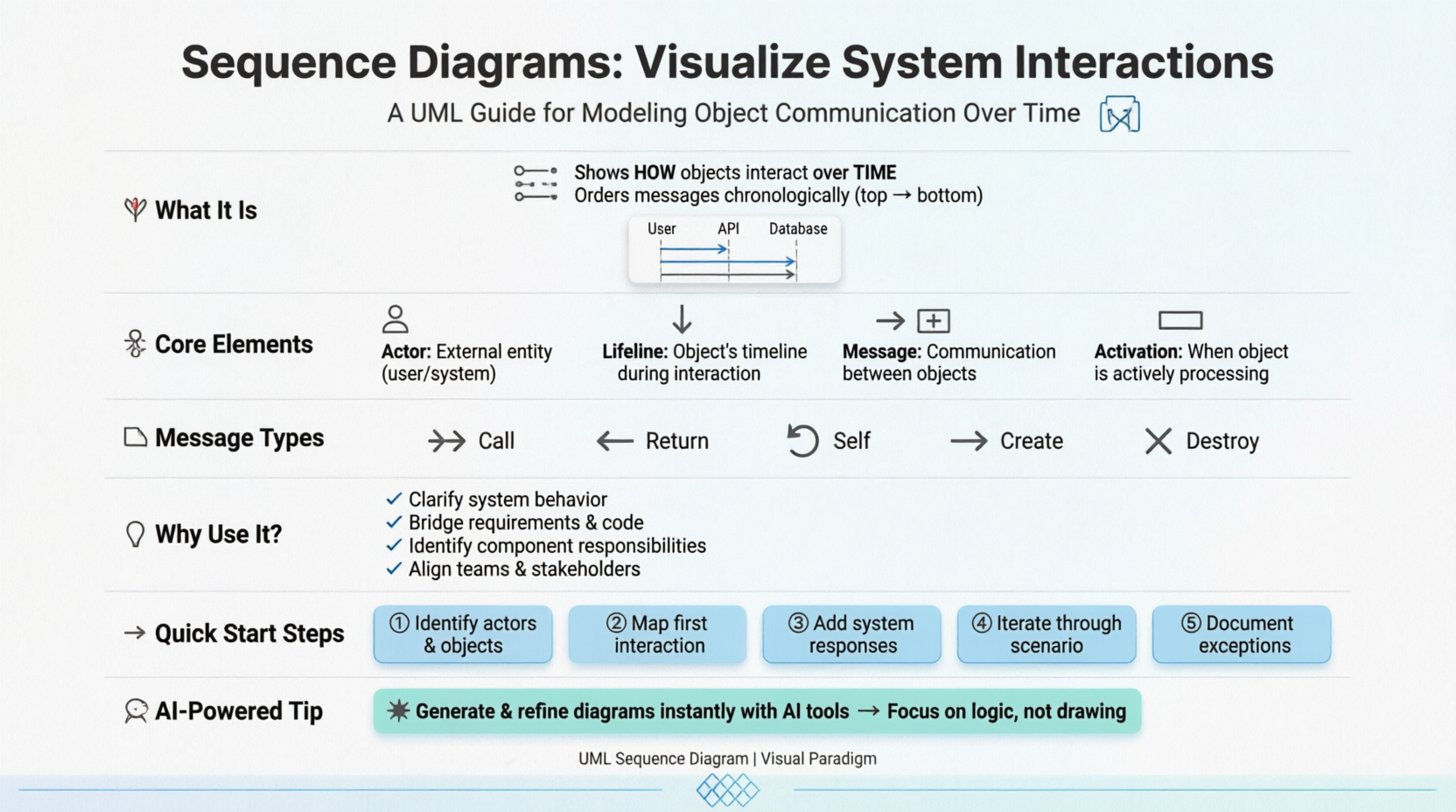
A sequence diagram is a type of UML (Unified Modeling Language) diagram that shows how objects interact with each other over time. It focuses on the order of messages exchanged, making it one of the most practical tools for modeling system behavior.
By visualizing these interactions, sequence diagrams help teams understand not just what a system does, but how different components collaborate to achieve it.
💡 Key Insight: Sequence diagrams are time-focused—they use the vertical axis to represent time, showing visually what messages are sent and when.
Key Elements of a Sequence Diagram
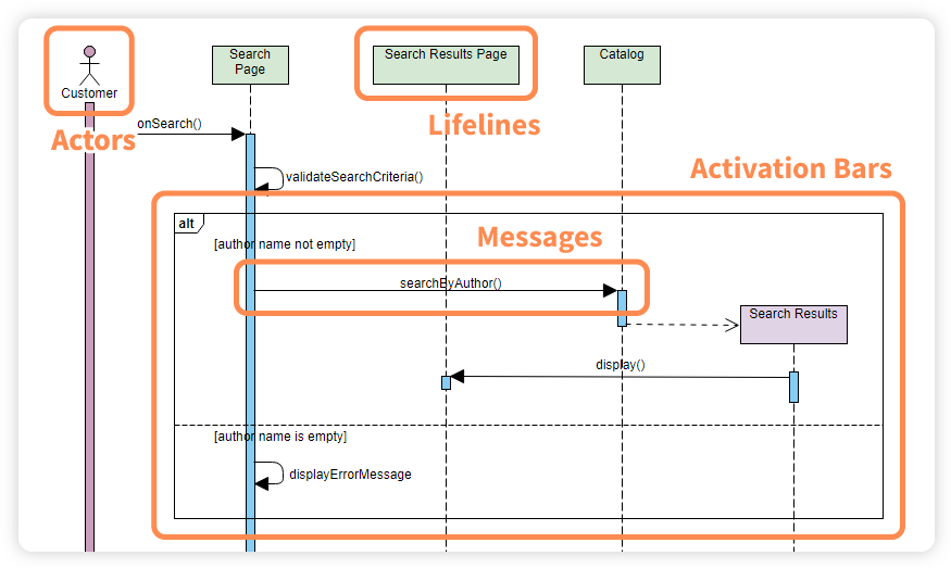
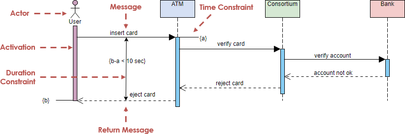
🔹 Actors
Represent the people, systems, or external entities interacting with the system. For example, a Customer in an ATM withdrawal scenario.

Important Notes:
-
An actor does not necessarily represent a specific physical entity but merely a particular role of some entity
-
A person may play the role of several different actors, and conversely, a given actor may be played by multiple different people
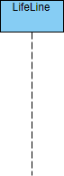
🔹 Lifelines
Vertical dashed lines that represent the lifespan of an object or component during the interaction.
🔹 Messages
Horizontal arrows showing communication between lifelines, such as requests, responses, or signals.
Types of Messages:
| Message Type | Description | Visual |
|---|---|---|
| Call Message | Invocation of an operation on the target lifeline | 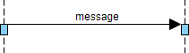 |
| Return Message | Pass of information back to the caller | 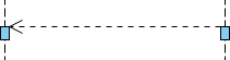 |
| Self Message | Invocation of a message on the same lifeline | 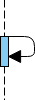 |
| Recursive Message | Message targeting an activation on top of the current activation |  |
| Create Message | Instantiation of a target lifeline | 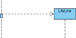 |
| Destroy Message | Request to destroy the lifecycle of target lifeline | 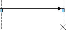 |
| Duration Message | Shows time distance between two instants for a message | 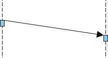 |
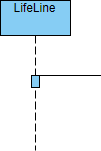
🔹 Activation Bars
Rectangles placed on lifelines, representing the time an object is actively performing an operation. The top and bottom of the rectangle align with the initiation and completion time respectively.
🔹 Notes (Comments)
A note gives the ability to attach various remarks to elements. A comment carries no semantic force but may contain information useful to a modeler.

Why Sequence Diagrams Matter
Sequence diagrams are widely used in software design because they:
✅ Clarify system behavior by showing the order of interactions
✅ Serve as a bridge between requirements and implementation
✅ Help identify responsibilities of different components
✅ Provide shared understanding across stakeholders, developers, and testers
✅ Reduce design errors through visual validation
Whether in small applications or enterprise systems, they improve communication and make complex workflows easier to understand.
When to Draw a Sequence Diagram?
Use sequence diagrams when you need to:
-
Model high-level interactions between active objects in a system
-
Model interactions between object instances within a collaboration that realizes a use case
-
Model interactions within a collaboration that realizes an operation
-
Represent either:
-
Generic interactions (showing all possible paths through the interaction), OR
-
Specific instances of an interaction (showing just one path)
-
Levels of Granularity
Sequence diagrams can capture interactions at different levels:
| Level | Description | Example |
|---|---|---|
| System Level | High-level interactions between users and the system, or between systems | System Sequence Diagrams |
| Use Case Level | Interactions that realize a specific use case or operation | Instance or Generic Diagrams |
| Architecture Level | Object interactions in MVC (Model-View-Controller) patterns | Framework Design |
How to Draw a Sequence Diagram: Step-by-Step
Step 1: Identify Participants
Identify a set of objects that will participate in the collaboration or use case scenario.
-
If deriving from a use case, start with the normal scenario first
-
Identify the primary actor(s) who activates the use case
Step 2: Start with the First Interaction
Consider the first point of the scenario or flow of events.
Step 3: Map System Responses
For each actor message, determine:
-
What does the system need to handle before responding?
-
What internal objects are involved?
Example: When a customer inserts an ATM card:
Customer → ATM: Insert Card
ATM → Card Reader: Read & Verify Card
Card Reader → Bank System: Validate Card Holder
Bank System → ATM: Request PIN
ATM → Customer: Display "Enter PIN"
Step 4: Iterate Through the Scenario
Repeat for each point in the scenario until all interactions are mapped.
Step 5: Handle Exceptions (Optional but Recommended)
Draw corresponding sequence diagrams for alternative or exception scenarios.
💡 Pro Tip: Use the information gathered during sequence diagram creation as a basis to incrementally derive your class diagram.
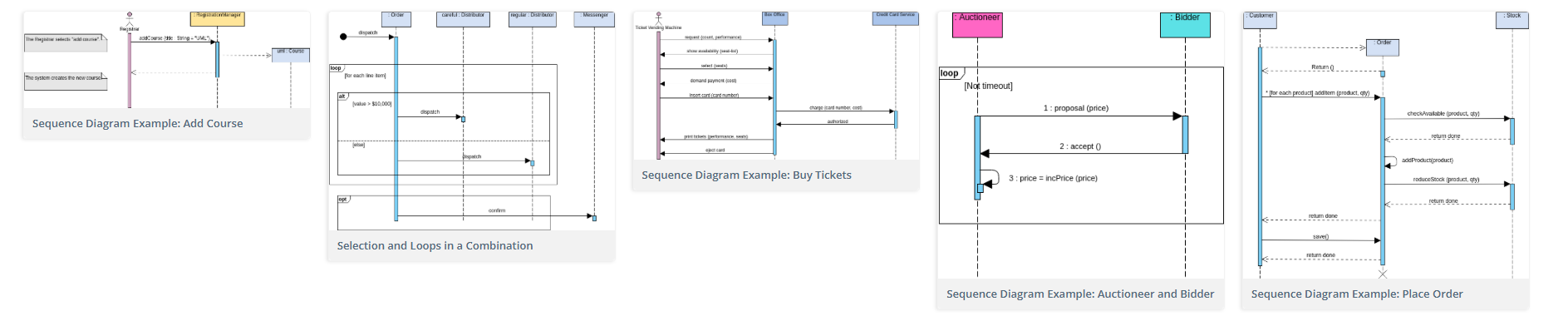
Sequence Diagram Examples
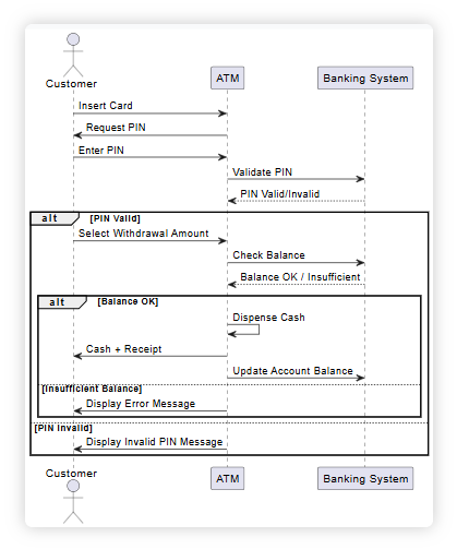
🏧 Example 1: ATM Withdraw Cash Scenario
Imagine a customer withdrawing cash from an ATM:
-
Customer inserts card → ATM requests PIN
-
Customer enters PIN → ATM validates it with banking system
-
Customer selects amount → ATM checks balance and dispenses cash
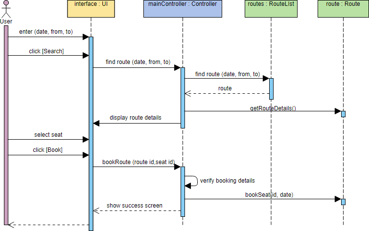
🎫 Example 2: Ticket Booking System
This example shows interactions between a user and a ticket booking system when booking a seat. It includes:
-
Actor: The user
-
Boundary Object: Interface
-
Controller Object: mainController
-
Entity Objects: routes and route
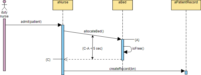
🏥 Example 3: Hospital Bed Allocation
This example demonstrates a patient admission process, showcasing the use of timing and duration constraints.
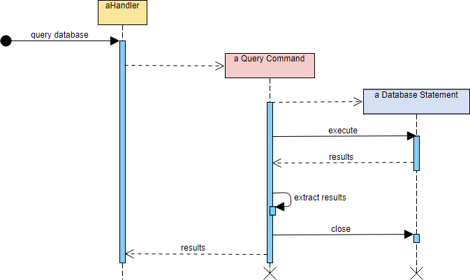
🔄 Example 4: Object Creation and Recursive Messages
This example illustrates how recursive messages and object creation/deletion can be modeled in interaction diagrams.
🤖 Generate Sequence Diagrams Instantly with AI!
Traditionally, creating detailed sequence diagrams can be time-consuming. Modern AI-powered tools now make this process faster and more accessible.
The AI-Powered Workflow:
-
Start Simple: Sketch a basic diagram using actors and main interactions
-
Refine with AI: Use AI tools (like the Visual Paradigm AI Chatbot) to expand your diagram into detailed MVC components
-
Customize in Editor: Open the refined diagram in a visual editor to adjust, document, or integrate with other UML diagrams
Real-World Demo: Washing Machine Scenario
In a recent product demonstration, the Visual Paradigm AI chatbot was used to generate a UML sequence diagram illustrating the normal scenario for washing clothes by a washing machine.
Key Benefits of AI Generation:
-
✨ Iterative Refinement: Start with a basic diagram and request more details
-
💧 Contextual Expansion: Ask the AI to add specific flows (e.g., “add water supply request”)
-
🔄 Seamless Integration: Press “Import to Visual Paradigm” to bring the generated diagram directly into your project for further editing
🎯 Stop drawing. Start generating. AI tools help you create accurate UML sequence diagrams instantly, so you can focus on design logic rather than diagram mechanics.
Try It Yourself! 🚀
Want to create your own sequence diagram online?
→ Draw Now with Visual Paradigm Online
Visual Paradigm Online is free* and intuitive. You can also review this tutorial to learn about sequence diagrams before you get started.
Quick Reference Cheat Sheet
| Element | Symbol | Purpose |
|---|---|---|
| Actor | 👤 Stick figure | External entity interacting with system |
| Lifeline | ⬇️ Dashed vertical line | Represents object’s existence over time |
| Activation | ▭ Rectangle on lifeline | Shows when object is performing an action |
| Call Message | → Solid arrow | Invokes an operation |
| Return Message | ⇢ Dashed arrow | Returns control/data to caller |
| Self Message | ↪ Curved arrow | Object calls its own method |
| Create Message | ➕ Dashed arrow with arrowhead | Instantiates a new object |
| Destroy Message | ✖ Dashed arrow with X | Ends an object’s lifecycle |
| Note | 📝 Folded corner box | Adds explanatory comments |
Best Practices for Effective Sequence Diagrams
✅ Keep it focused: One diagram per scenario or use case
✅ Use clear names: Label messages with meaningful verbs (e.g., validatePIN(), checkBalance())
✅ Limit complexity: If a diagram gets too crowded, break it into sub-diagrams
✅ Include timing constraints when performance matters
✅ Document assumptions using notes for edge cases
✅ Validate with stakeholders: Use diagrams as communication tools, not just documentation
Reference List
- AI Sequence Diagram Example: Video Streaming Playback: A concrete example demonstrating how Visual Paradigm’s AI generates a sequence diagram for a video streaming playback scenario.
- YouTube: Visual Paradigm AI Sequence Diagram Tutorial: A video tutorial showcasing the features and usage of Visual Paradigm’s AI sequence diagram capabilities.
- AI Sequence Diagram Example: Online Payment Processing System: An example illustrating an AI-generated sequence diagram for an online payment processing system workflow.
- UML Sequence Diagram: A Definitive Guide to Modeling Interactions with AI: A comprehensive guide explaining UML sequence diagrams and how to leverage AI tools to model system interactions effectively.
- AI Sequence Diagram Refinement Tool: The official feature page detailing Visual Paradigm’s tool for refining and editing AI-generated sequence diagrams.
- Visual Paradigm Chat Interface: The main portal for accessing Visual Paradigm’s AI chat interface for generating diagrams and documentation.
- YouTube: Advanced Sequence Diagram Features: A video demonstration focusing on advanced features within Visual Paradigm’s diagramming suite.
- YouTube: Step-by-Step Sequence Diagram Creation: A video walkthrough showing the step-by-step process of creating sequence diagrams using Visual Paradigm.
- YouTube: Introduction to Visual Paradigm Tools: An introductory video overview of Visual Paradigm’s modeling and design tools.
- YouTube: Deep Dive into Sequence Diagrams: A detailed video analysis of complex sequence diagram patterns and best practices.
- AI Sequence Diagram Example: Software Update Download & Install: A practical example of an AI-generated sequence diagram depicting a software update download and installation process.
📌 Final Thought: Sequence diagrams are more than just documentation—they’re living artifacts that bridge the gap between requirements, design, and implementation. Whether you’re sketching on a whiteboard or generating with AI, the goal remains the same: make system interactions clear, collaborative, and correct.
Happy diagramming! 🎨✨
This post is also available in Deutsch, Español, فارسی, Français, English, Bahasa Indonesia, 日本語, Polski, Portuguese, Ру́сский, Việt Nam, 简体中文 and 繁體中文.