


What is a C4 Code Diagram?
The Code diagram is Level 4 — the deepest, most detailed level in Simon Brown’s C4 model.
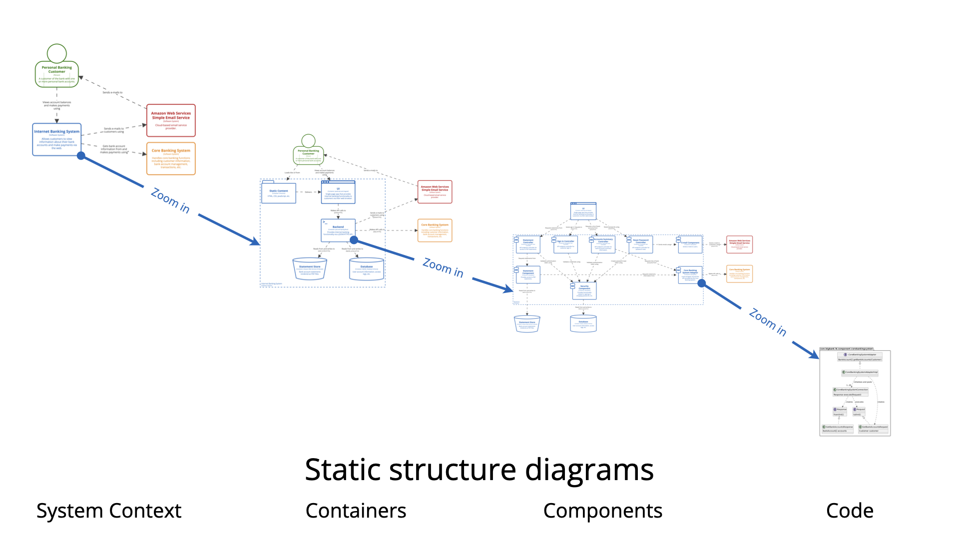
It shows:
-
Classes, interfaces, enums, records, or other code-level constructs that implement a specific component (from Level 3).
-
Relationships between those classes (inheritance, composition, dependency, realization of interfaces, etc.).
-
Key design elements such as patterns applied inside the component (e.g., repositories, services, DTOs, domain entities, factories).
In practice, this level is almost always a UML class diagram (or a simplified variant) focused on one (or very few) components.
Important clarification:
-
Level 4 is not about the entire codebase.
-
It is not required to show every class.
-
It maps only the essential structure needed to understand how a complex or critical component is actually built.
-
The official C4 recommendation: ideally auto-generated from source code (via tools like Doxygen, Javadoc + UML plugins, yWorks, Structurizr, CodeSee, etc.) rather than hand-drawn.
When to Create a Code Diagram
Create Level 4 diagrams sparingly — only in these situations:
-
The component is highly complex, mission-critical, or difficult to understand from source code alone (e.g., intricate domain logic, heavy use of design patterns, cryptographic flows, state machines, legacy code riddled with technical debt).
-
You are working in a highly regulated industry (finance, healthcare, aerospace, defense) where auditors or compliance teams demand explicit mapping from architecture → design → implementation.
-
During major refactoring, strangling a legacy component, or introducing a new architectural pattern (hexagonal, clean, vertical slice, DDD aggregates) — before/after views help communicate the change.
-
Onboarding senior developers or architects who need to quickly grasp non-obvious internal structure of a high-risk piece of code.
-
You have already invested in auto-generation tooling — so maintaining Level 4 costs almost nothing.
-
The team has agreed that “living documentation” at class level is valuable for this specific subsystem.
Do NOT create Level 4 diagrams when:
-
The component structure is obvious from good naming, small size, or clean code (most modern microservices fall here).
-
You already have good unit/integration tests, clear interfaces, and explanatory comments.
-
Most of the team can navigate the code easily.
-
Maintenance cost outweighs benefit (hand-drawn class diagrams go stale very quickly).
Simon Brown and most practitioners emphasize: Most teams never need Level 4. Levels 1 + 2 cover 80–90% of communication needs; Level 3 handles most of the rest. Level 4 is the exception, not the rule.
Why Use Code Diagrams? (When They Add Value)
-
Bridge architecture ↔ implementation — Shows how high-level components are actually realized in code.
-
Clarify complex internal design — Exposes use of patterns (Strategy, Factory, Decorator, Repository), layering violations, tight coupling, or clever domain modeling.
-
Support audits & compliance — Demonstrates that architectural decisions are followed through to code.
-
Aid refactoring & migration discussions — Before/after class structures make proposals tangible.
-
Reduce “tribal knowledge” — Helps new senior hires understand non-trivial parts faster than reading all source files.
-
Auto-generated versions become “living docs” — If tooling is in place, they stay accurate with almost zero effort.
How to Create a Great Code Diagram (Step-by-Step + Best Practices)
-
Pick ONE component — Usually from a Level 3 diagram where internal complexity justifies the zoom.
-
Decide: hand-drawn or generated?
-
Hand-drawn → only for workshops, proposals, or areas too messy for auto-tools.
-
Generated → preferred (PlantUML can still be used to style/tweak the output).
-
-
Focus on essentials — Show:
-
Key classes/interfaces
-
Important relationships (→ dependency, — composition, <| realization, ^ inheritance)
-
Aggregates, entities, value objects (DDD style)
-
Critical patterns or anti-patterns you want to highlight
-
-
Keep it small — 8–15 classes maximum. If larger → split into focused diagrams (e.g., “Authentication slice”, “Order processing entities”).
-
Best Practices
-
Prefer auto-generation whenever possible (less staleness).
-
Use PlantUML classDiagram syntax — clean and versionable.
-
Add notes for non-obvious decisions (e.g., “Uses Anemic Domain Model – planned refactor”).
-
Avoid showing everything — omit trivial getters/setters, utility classes.
-
Store in repo → treat as code (commit .puml files near the component).
-
Use sparingly — one per complex component, not per microservice.
-
Combine with dynamic views (sequence/collaboration) if runtime flow is more important than static structure.
-
PlantUML Example – Authentication Component (Big Bank plc style extension)
Here is a realistic Level 4 example zooming into the Security / Authentication Component from the earlier API Application diagrams.
@startuml
title C4 Level 4 – Code Diagram: Authentication inside API Application

skinparam monochrome true
skinparam shadowing false
skinparam class {
  BackgroundColor White
  BorderColor Black
  ArrowColor Black
}

abstract class AuthenticationProvider {
  + authenticate(credentials): Authentication
}

class JwtAuthenticationProvider {
  - tokenProvider: JwtTokenProvider
  - userDetailsService: UserDetailsService
  + authenticate(credentials): Authentication
}

class JwtTokenProvider {
  - secretKey: String
  - validityInMilliseconds: long
  + generateToken(userDetails): String
  + validateToken(token): boolean
  + getUsernameFromToken(token): String
}

interface UserDetailsService {
  + loadUserByUsername(username): UserDetails
}

class DatabaseUserDetailsService {
  - userRepository: UserRepository
  + loadUserByUsername(username): UserDetails
}

class UserRepository {
  + findByUsername(username): Optional<User>
}

class User {
  - username: String
  - passwordHash: String
  - roles: Set<Role>
}

class JwtAuthenticationToken << (T,orchid) Authentication >> {
  - principal: UserDetails
  - credentials: Object
  - authorities: Collection<GrantedAuthority>
}

' Relationships
JwtAuthenticationProvider -up-> JwtTokenProvider : uses
JwtAuthenticationProvider -up-> UserDetailsService : uses
DatabaseUserDetailsService .up.|> UserDetailsService
DatabaseUserDetailsService --> UserRepository : uses
UserRepository --> User : returns

JwtAuthenticationToken .up.|> Authentication

note right of JwtAuthenticationProvider
  Primary authentication flow for JWT-based stateless sessions
end note

note bottom of JwtTokenProvider
  Signs & verifies JWTs using HS512
end note

@enduml
This small diagram:
-
Focuses only on authentication internals
-
Shows key classes, interfaces, and dependencies
-
Highlights patterns (provider, repository)
-
Uses notes for context
Paste into any PlantUML renderer — customize for your domain (e.g., replace JWT with OAuth2, add MFA classes, etc.).
Summary reminder: Level 4 is powerful but rare. Use it intentionally, prefer auto-generation, and never let it become busywork. Most value in C4 comes from Levels 1–3. Happy (selective) modeling!
Resource
- Ultimate Guide to C4 Model Visualization Using Visual Paradigm’s AI Tools: This guide explains how to leverage AI-powered tools to automate and enhance C4 model visualization for faster software architecture design.
- Leveraging Visual Paradigm’s AI C4 Studio for Streamlined Architecture Documentation: This article details using an AI-enhanced studio to create clean, scalable, and maintainable software architecture documentation.
- The Ultimate Guide to C4-PlantUML Studio: Revolutionizing Software Architecture Design: This resource explores combining AI-driven automation, the C4 model’s clarity, and PlantUML’s flexibility into a single powerful tool.
- A Comprehensive Guide to Visual Paradigm’s AI-Powered C4 PlantUML Studio: This guide describes a purpose-built tool released in late 2025 that transforms natural language prompts into layered C4 diagrams.
- C4-PlantUML Studio | AI-Powered C4 Diagram Generator: This feature overview highlights an AI-driven tool designed to generate C4 software architecture diagrams from simple text descriptions.
- Generating and Modifying C4 Component Diagrams with Visual Paradigm AI Chatbot: This tutorial demonstrates using an AI-powered chatbot to iteratively create and refine component-level architecture for complex systems.
- AI-Powered C4 Diagram Generator: Core Levels and Supporting Views: This page explains how the AI generator supports the four core levels of the C4 model—Context, Container, Component, and Deployment—to provide comprehensive documentation.
- AI Diagram Generator: Complete C4 Model Support Release: This update details the integration of AI-powered features for the automated creation of hierarchical C4 model diagrams.
- C4 Model AI Generator: Automating the Full Modeling Lifecycle: This resource highlights how a specialized AI chatbot uses conversational prompts to ensure consistency across architecture documentation for DevOps teams.
- Comprehensive Review: Generic AI Chatbots vs. Visual Paradigm’s C4 Tools: This comparison explains why specialized tools like the C4 PlantUML Studio provide more structured and professional-grade results than general-purpose language models.
This post is also available in Deutsch, Español, فارسی, Français, English, Bahasa Indonesia, 日本語, Polski, Portuguese, Ру́сский, Việt Nam, 简体中文 and 繁體中文.