
Introduction
Visual modeling has traditionally meant opening a dedicated UML tool, selecting diagram elements, placing them on a canvas, and manually arranging relationships. Visual Paradigm UML follows this established approach with a full-featured graphical modeling environment for software architects, analysts, developers, and project teams.
VPasCode represents a newer approach: Diagram-as-Code. Instead of drawing each element manually, users describe diagrams using text-based syntax such as PlantUML, Mermaid, D2, or Graphviz. The editor then interprets that source code and renders the result as a visual diagram.
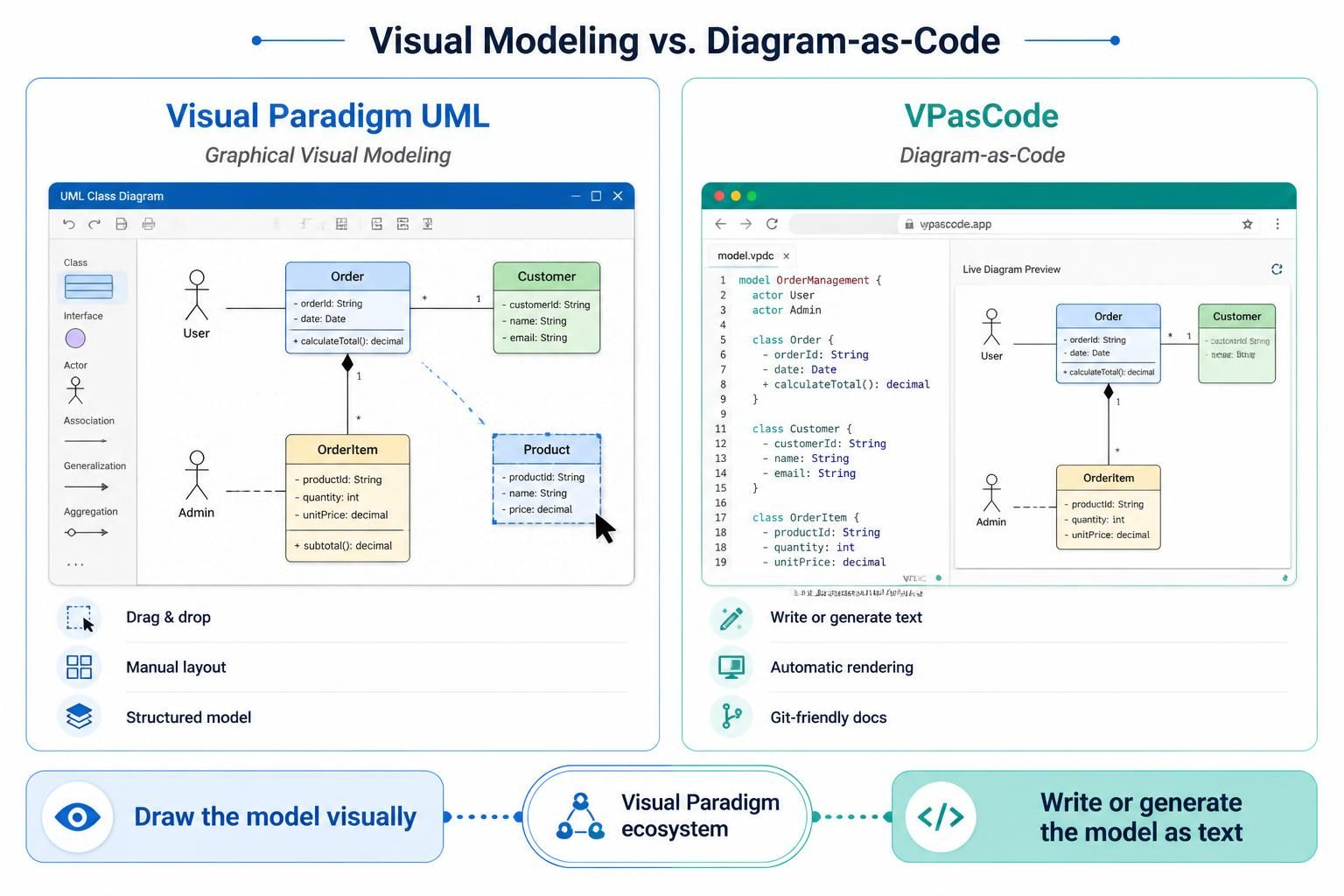
Both approaches belong to the Visual Paradigm ecosystem, but they serve different working styles. Visual Paradigm UML is centered on interactive visual modeling and structured project repositories. VPasCode is optimized for text-based authoring, browser-based workflows, rapid iteration, artificial intelligence assistance, and documentation that can evolve alongside source code.
The most important difference is simple:
-
Visual Paradigm UML: Draw the model visually.
-
VPasCode: Write or generate the model as text and render it automatically.
What Is Visual Paradigm UML?
Visual Paradigm UML is a traditional visual modeling suite designed for creating and managing software models through a graphical user interface.
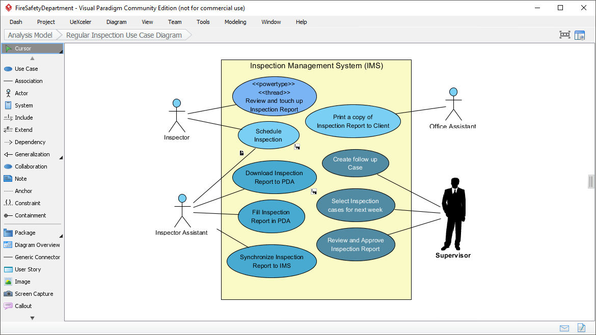
Users can create diagrams by:
-
Selecting UML elements from palettes
-
Dragging classes, actors, components, states, and activities onto a canvas
-
Drawing relationships between elements
-
Arranging and aligning objects manually
-
Editing labels and properties through dialogs
-
Organizing multiple diagrams inside a modeling project
-
Connecting diagrams to requirements, database models, source code, and documentation
This approach is familiar to business analysts, software architects, system designers, and stakeholders who prefer working directly with visual shapes.
Visual Paradigm UML is especially useful when a project requires more than an isolated diagram. A complete modeling project may include requirements, use cases, class diagrams, sequence diagrams, database designs, deployment diagrams, process models, and traceability links between them.
What Is VPasCode?
VPasCode is Visual Paradigm’s browser-based Diagram-as-Code editor. It allows users to create diagrams by writing text-based definitions instead of positioning every object manually.
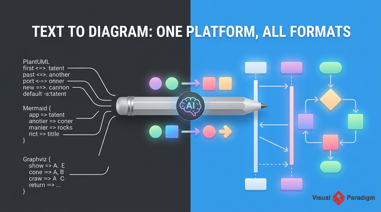
The editor supports multiple diagramming formats, including:
-
PlantUML
-
Mermaid
-
D2
-
Graphviz
-
Code-based diagram definitions
-
Data and schema visualization formats
A typical VPasCode workspace contains a text editor and a live diagram preview. As the diagram source changes, the rendered output can be updated automatically.

VPasCode is designed for users who prefer:
-
Text editors over graphical palettes
-
Git-based workflows
-
Reusable diagram templates
-
Automated rendering
-
Browser-based tools
-
AI-assisted generation and editing
-
Documentation stored alongside software projects
It can also connect with other Visual Paradigm capabilities, including AI-assisted diagram generation, OpenDocs documentation, Visual Paradigm Online, and Visual Paradigm Desktop.
Core Difference: Graphical Modeling vs. Diagram-as-Code
The primary distinction is how the diagram is created.
With Visual Paradigm UML, the diagram itself is the main working surface. The user manipulates visual objects directly. With VPasCode, the textual definition is the primary source, and the diagram is rendered from that source.
For example, a simple PlantUML class diagram might look like this:
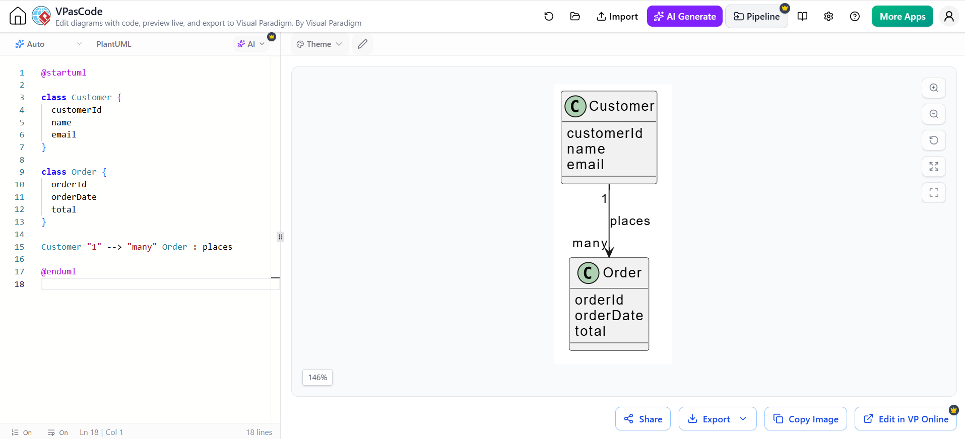
@startuml

class Customer {
  customerId
  name
  email
}

class Order {
  orderId
  orderDate
  total
}

Customer "1" --> "many" Order : places

@enduml
The user does not manually draw two class boxes or position an association line. Instead, the text describes the classes and their relationship, while the rendering engine creates the visual layout.
This produces a different design experience:
| Area | Visual Paradigm UML | VPasCode |
|---|---|---|
| Primary interface | Graphical canvas | Text editor and live preview |
| Diagram creation | Drag and drop | Text syntax or AI generation |
| Layout control | Manual positioning and alignment | Automatic rendering with syntax-based adjustments |
| Source format | Project and model files | Text-based diagram definitions |
| Collaboration | Model repositories and project sharing | Shareable sources, links, and repository workflows |
| Version control | Specialized model comparison may be required | Line-based text diffs work naturally |
| Setup | Desktop or configured modeling environment | Browser-based workspace |
| Best fit | Comprehensive visual modeling | Fast, repeatable, developer-oriented diagrams |
Key Concepts
1. Unified Modeling Language
Unified Modeling Language is a standardized visual language for describing software systems, business processes, structures, and interactions.
Common UML diagram types include:
-
Use case diagrams: Show actors and system functions.
-
Class diagrams: Show classes, attributes, operations, and relationships.
-
Sequence diagrams: Show interactions over time.
-
Activity diagrams: Show workflows and business processes.
-
State-machine diagrams: Show the states and transitions of an object or system.
-
Component diagrams: Show software modules and dependencies.
-
Deployment diagrams: Show how software is deployed across infrastructure.
-
Package diagrams: Organize model elements into logical groups.
Visual Paradigm UML provides graphical support for these diagrams, while VPasCode can generate several UML-style diagrams through text-based engines such as PlantUML and Mermaid.
2. Diagram-as-Code
Diagram-as-Code applies software development principles to visual documentation.
Instead of storing only a finished image, the team stores the instructions needed to generate the image. This means diagrams can be:
-
Edited as text
-
Reviewed line by line
-
Stored in Git
-
Reused through templates
-
Regenerated consistently
-
Updated alongside application code
-
Embedded into technical documentation pipelines
For example, a change from one service to two services can be reviewed as a text change:
- PaymentService --> OrderService
+ PaymentService --> OrderService
+ FraudDetectionService --> PaymentService
The exact diff depends on the chosen syntax, but the principle is the same: the structural change becomes visible in version control.
3. Model Repository vs. Text Repository
Traditional UML tools often store models in structured project files or specialized repositories. These repositories can contain more than the visible diagram, including metadata, relationships, requirements, model properties, and traceability information.
VPasCode generally treats the diagram definition as a text artifact. A team can store a file such as the following in a project repository:
docs/
  architecture/
    system-context.puml
    deployment.mmd
    checkout-sequence.puml
This makes diagrams easier to place alongside:
-
Application source code
-
README files
-
Architecture decision records
-
Infrastructure definitions
-
API specifications
-
Build and deployment documentation
4. Automatic Layout
In a graphical UML tool, the user can manually control the position of individual shapes. This provides precise visual control but can become time-consuming as diagrams grow.
Diagram-as-Code tools generally calculate the layout automatically. This is useful for:
-
Repeated documentation builds
-
Large dependency diagrams
-
Automatically generated architecture maps
-
Continuous integration pipelines
-
Diagrams that change frequently
Automatic layout is not always perfect. Complex diagrams may require grouping, direction settings, hidden relationships, ranking hints, or other syntax adjustments. However, the source remains reproducible, and layout changes can be regenerated after each update.
5. AI-Assisted Diagram Generation
VPasCode incorporates AI features that can help generate or modify diagram source code from natural-language instructions.
A user might enter a prompt such as:
Create a sequence diagram for a customer logging into a web application using a browser, authentication service, user database, and access token.
The AI can generate an initial PlantUML or Mermaid definition. The user can then:
-
Review the generated source.
-
Inspect the rendered diagram.
-
Correct inaccurate assumptions.
-
Rename components using project terminology.
-
Add missing actors or services.
-
Adjust relationships and sequence order.
-
Apply a consistent visual theme.
-
Save the final source in the project repository.
AI is most useful as an accelerator. It can produce a first draft quickly, but technical teams should still validate architecture boundaries, security assumptions, business rules, and system dependencies.
Example 1: Creating a Class Diagram
Visual Paradigm UML workflow
A typical graphical workflow would be:
-
Create a new UML project.
-
Add a class diagram.
-
Drag
CustomerandOrderclass elements onto the canvas. -
Add attributes and operations.
-
Draw an association between the classes.
-
Set multiplicities such as one-to-many.
-
Align and format the diagram.
-
Save the model in the project repository.
This is intuitive for users who prefer direct manipulation and visual feedback.
VPasCode workflow
The same design could be written in PlantUML:
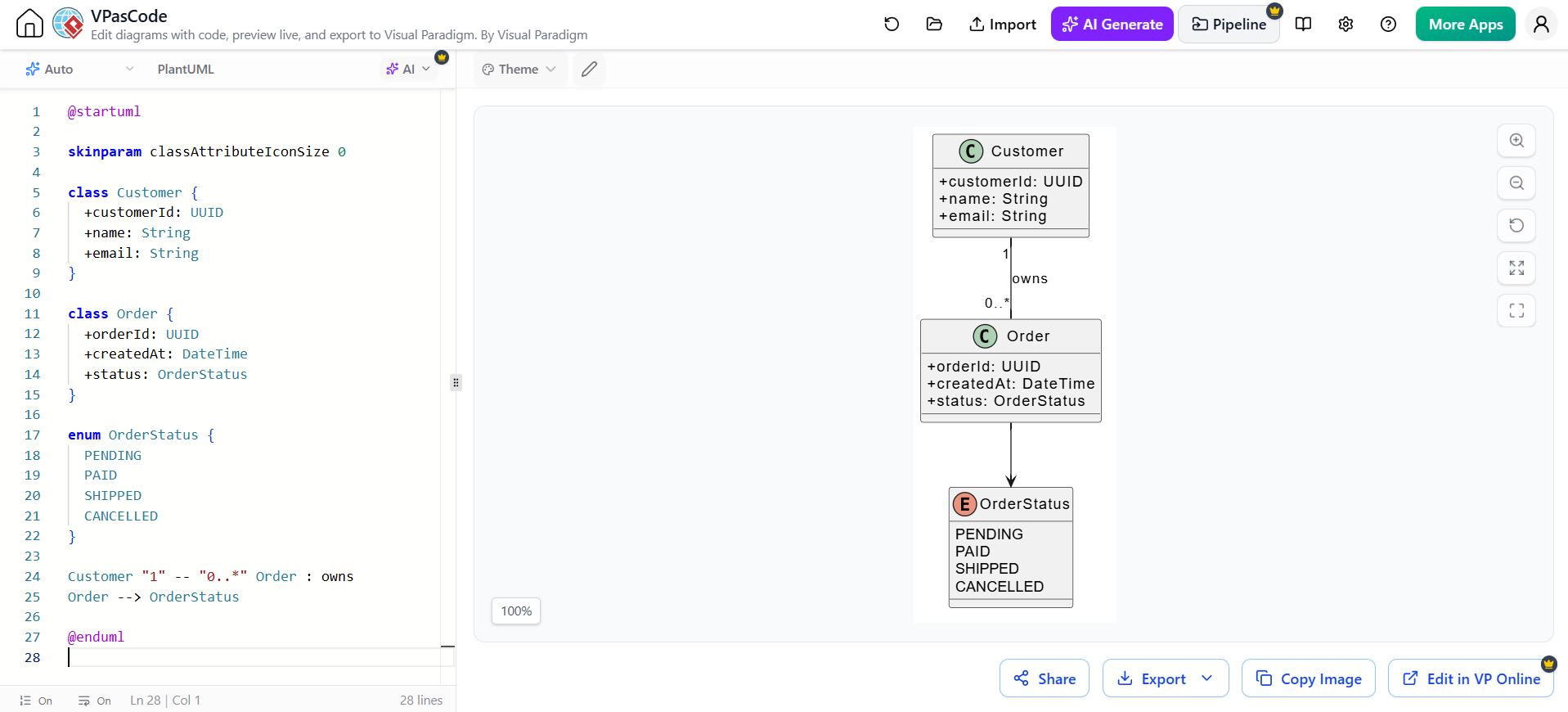
@startuml

skinparam classAttributeIconSize 0

class Customer {
  +customerId: UUID
  +name: String
  +email: String
}

class Order {
  +orderId: UUID
  +createdAt: DateTime
  +status: OrderStatus
}

enum OrderStatus {
  PENDING
  PAID
  SHIPPED
  CANCELLED
}

Customer "1" -- "0..*" Order : owns
Order --> OrderStatus

@enduml
This approach makes the model structure explicit and easy to modify. Adding a new property usually means changing one line rather than opening multiple property dialogs.
Example 2: Creating a Sequence Diagram
A login flow can be represented with PlantUML as follows:
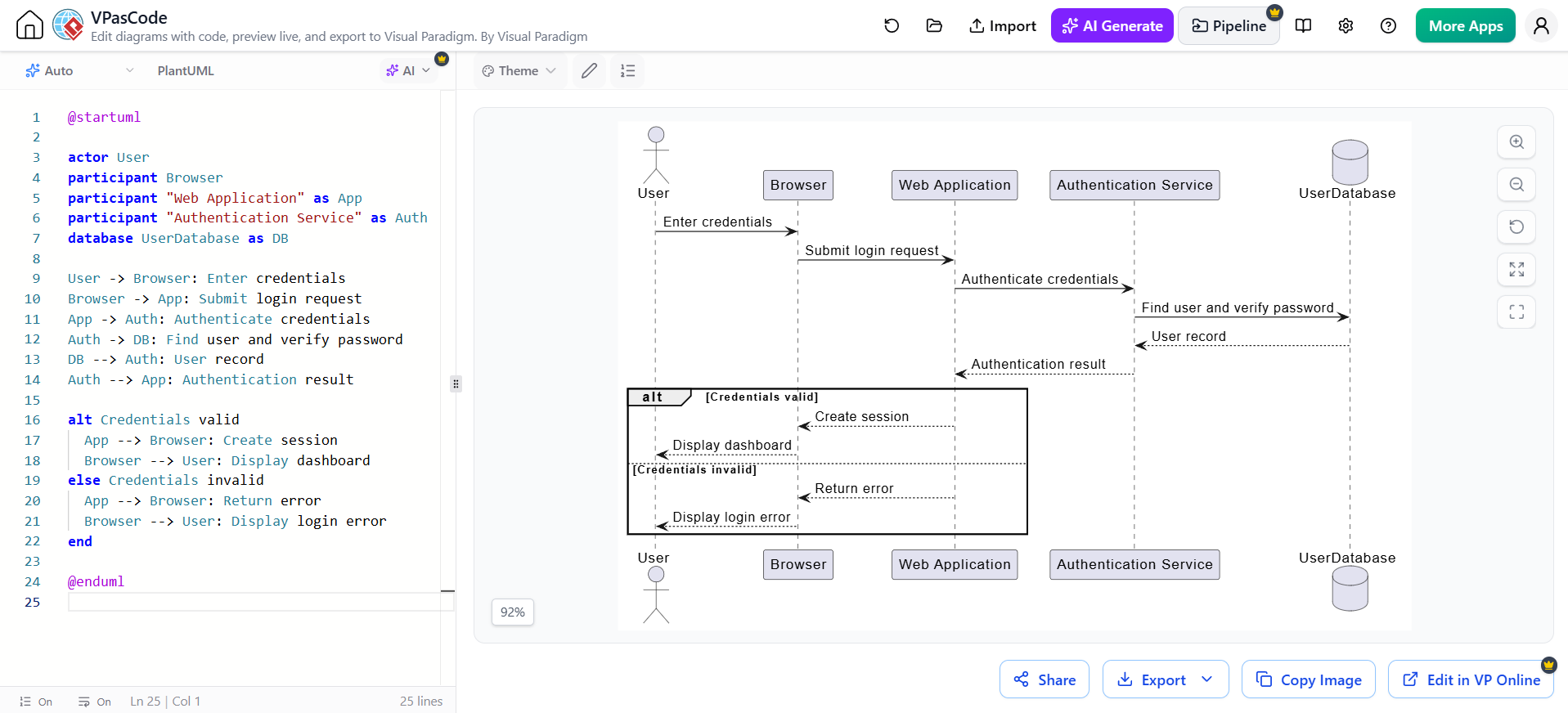
@startuml

actor User
participant Browser
participant "Web Application" as App
participant "Authentication Service" as Auth
database UserDatabase as DB

User -> Browser: Enter credentials
Browser -> App: Submit login request
App -> Auth: Authenticate credentials
Auth -> DB: Find user and verify password
DB --> Auth: User record
Auth --> App: Authentication result

alt Credentials valid
  App --> Browser: Create session
  Browser --> User: Display dashboard
else Credentials invalid
  App --> Browser: Return error
  Browser --> User: Display login error
end

@enduml
In a graphical UML tool, each participant and message is created through visual elements. In VPasCode, the sequence and alternative path are represented in the source itself.
This is particularly helpful when the sequence changes frequently during API or authentication development.
Example 3: Creating an Architecture Diagram with Mermaid
Mermaid is often convenient for lightweight documentation and Markdown-based repositories.
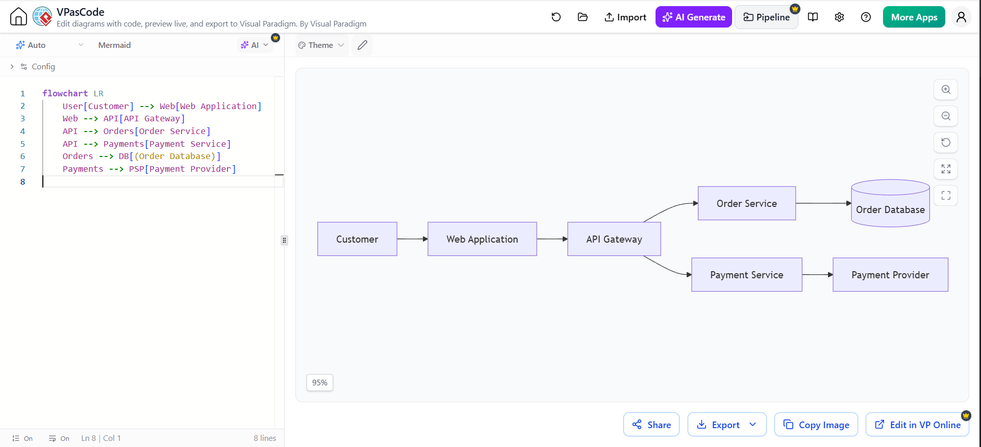
flowchart LR
    User[Customer] --> Web[Web Application]
    Web --> API[API Gateway]
    API --> Orders[Order Service]
    API --> Payments[Payment Service]
    Orders --> DB[(Order Database)]
    Payments --> PSP[Payment Provider]
This diagram can be placed directly inside Markdown documentation when the target documentation system supports Mermaid rendering.
A team might use Mermaid for README files and lightweight technical notes, while using PlantUML for more formal UML models.
Choosing the Right Diagram Engine
VPasCode’s multi-engine approach allows teams to select an appropriate syntax for different tasks.
| Engine | Strong fit | Typical use |
|---|---|---|
| PlantUML | Formal UML and detailed modeling | Class, sequence, activity, component, and deployment diagrams |
| Mermaid | Lightweight Markdown documentation | Flowcharts, sequence diagrams, state diagrams, and Git-based documentation |
| D2 | Expressive architecture and system diagrams | Application architecture, infrastructure, and conceptual maps |
| Graphviz | Relationship-focused graph layout | Dependency graphs, networks, pipelines, and hierarchies |
The best choice depends on the audience and the documentation environment. PlantUML is often appropriate when UML semantics and notation are important. Mermaid is convenient when diagrams live inside Markdown. Graphviz is valuable when relationship layout matters more than formal UML notation.
Visual Paradigm UML Strengths
Visual Paradigm UML is generally the stronger choice when a project requires comprehensive visual modeling.
Its advantages include:
-
Direct manipulation of diagram elements
-
Familiar notation for analysts and architects
-
Structured model organization
-
Support for multiple UML diagram types
-
Detailed visual formatting
-
Manual layout control
-
Broader modeling and design workflows
-
Suitability for workshops with nontechnical stakeholders
-
Integration with larger modeling projects
-
Support for forward and reverse engineering scenarios
A graphical environment is especially effective during collaborative design sessions where participants need to point at, move, and discuss elements on a shared canvas.
It is also useful when the model contains rich metadata or relationships that go beyond the visible diagram.
VPasCode Strengths
VPasCode is generally the stronger choice for fast, text-centered, and developer-oriented diagramming.
Its advantages include:
-
Browser-based access
-
No local installation required for the editor
-
Live rendering
-
Text-based source files
-
Git-friendly workflows
-
Easier line-by-line reviews
-
Reusable syntax and templates
-
Support for multiple diagram engines
-
AI-assisted generation
-
AI-assisted modification
-
AI-assisted syntax correction
-
Shareable diagrams and links
-
Image and vector export options
-
Connections to documentation workflows
It is especially useful when diagrams need to evolve with source code and technical documentation.
Collaboration and Version Control
The difference in collaboration models is significant.
A manually created diagram can be difficult to review in a code review. A reviewer may see that a model file changed, but understanding the exact architectural change may require opening the modeling application.
With Diagram-as-Code, changes are represented as text. For example:
 component "Order Service" as Orders
 component "Payment Service" as Payments
+component "Fraud Detection Service" as Fraud

 Web --> Orders
 Orders --> Payments
+Payments --> Fraud
This allows developers and architects to review changes using familiar tools such as:
-
Git
-
Pull requests
-
Branches
-
Commit history
-
Merge reviews
-
Continuous integration checks
The result is not that text-based diagrams replace model repositories in every situation. Rather, they provide a more natural workflow for teams already organized around source control.
AI Workflow in VPasCode
A productive AI-assisted workflow can follow these steps.
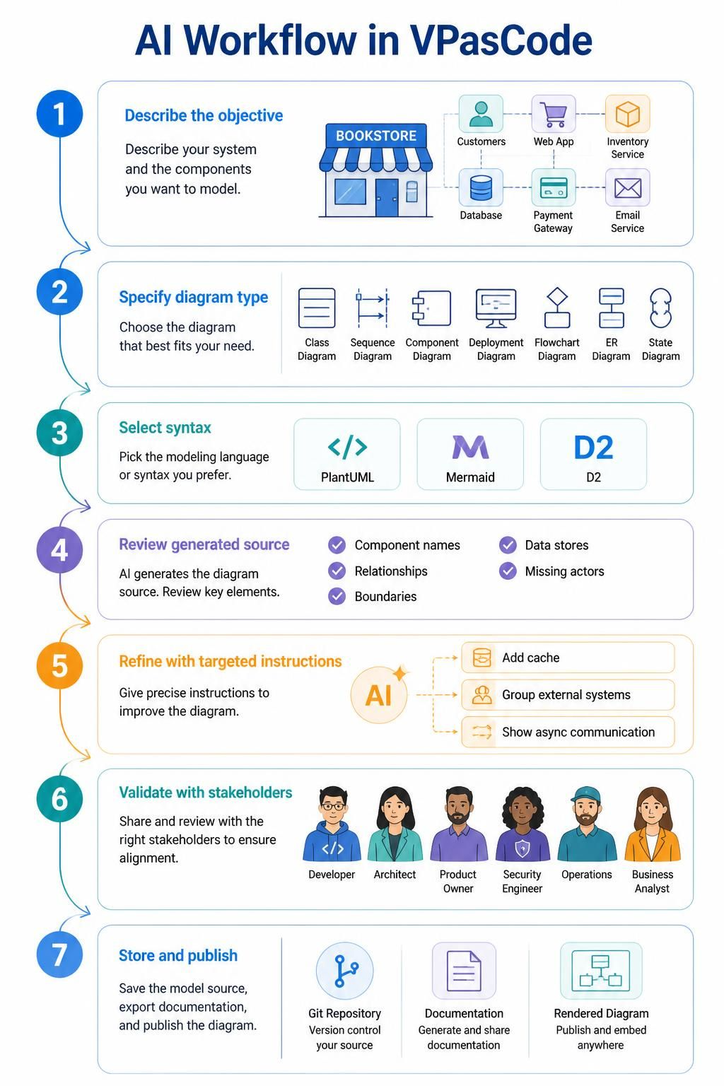
Step 1: Describe the objective
Explain what the diagram should communicate.
Example:
Show the components of an online bookstore and how customers, the web application, catalog service, order service, payment provider, and database interact.
Step 2: Specify the diagram type
Tell the AI whether the result should be a:
-
Class diagram
-
Sequence diagram
-
Component diagram
-
Deployment diagram
-
Flowchart
-
Entity-relationship diagram
-
State diagram
Step 3: Select the preferred syntax
Choose PlantUML, Mermaid, D2, or another supported format based on the target audience and repository.
Step 4: Review the generated source
Check:
-
Component names
-
Relationships
-
Direction of arrows
-
System boundaries
-
External dependencies
-
Security or trust boundaries
-
Data stores
-
Missing actors
-
Incorrect assumptions
Step 5: Refine with targeted instructions
Useful instructions include:
-
Add a cache between the API gateway and catalog service.
-
Group all external systems in a separate boundary.
-
Replace the payment provider with an abstract external service.
-
Show asynchronous communication between the order service and notification service.
-
Simplify the diagram to show only customer-facing components.
-
Rename all services using the project’s official terminology.
Step 6: Validate with stakeholders
AI-generated diagrams should be reviewed by the people who understand the system, including:
-
Developers
-
Solution architects
-
Product owners
-
Security engineers
-
Operations teams
-
Business analysts
Step 7: Store and publish the result
Save the final source with the project, export the rendered image if required, and publish it in technical documentation.
When to Choose Visual Paradigm UML
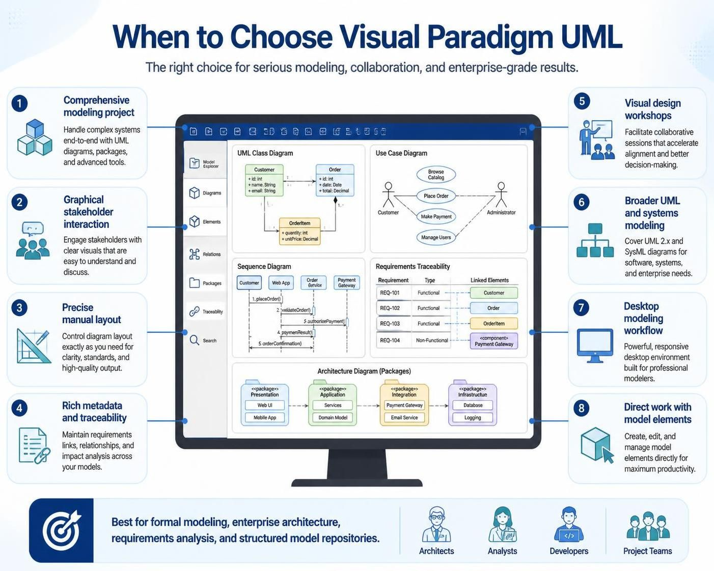
Choose Visual Paradigm UML when:
-
You need a comprehensive modeling project.
-
Stakeholders prefer graphical interaction.
-
You need precise manual layout control.
-
The model contains rich metadata and traceability relationships.
-
You are facilitating visual design workshops.
-
You need broader UML and systems modeling capabilities.
-
The diagram is part of an extensive desktop modeling workflow.
-
Analysts and architects need to work directly with model elements.
It is a strong choice for formal modeling, enterprise architecture, requirements analysis, and projects where diagrams are managed as part of a larger structured model.
When to Choose VPasCode
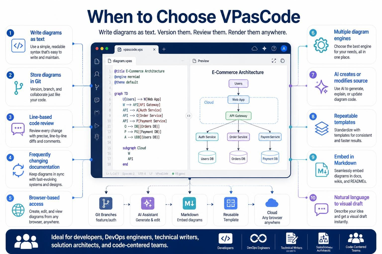
Choose VPasCode when:
-
You prefer writing diagrams as text.
-
Diagrams should live in Git repositories.
-
You need line-based code review.
-
Documentation changes frequently.
-
You want browser-based access.
-
You need multiple diagram engines in one workspace.
-
You want AI to create or modify diagram source.
-
You need repeatable diagrams generated from templates.
-
You want to embed diagrams in Markdown or developer documentation.
-
You want to move quickly from a natural-language idea to a visual draft.
VPasCode is particularly suitable for software development teams, DevOps engineers, technical writers, solution architects, and developers who already use code-centered workflows.
Using Both Tools Together
The choice does not have to be either-or. Visual Paradigm UML and VPasCode can be used at different stages of the same project.
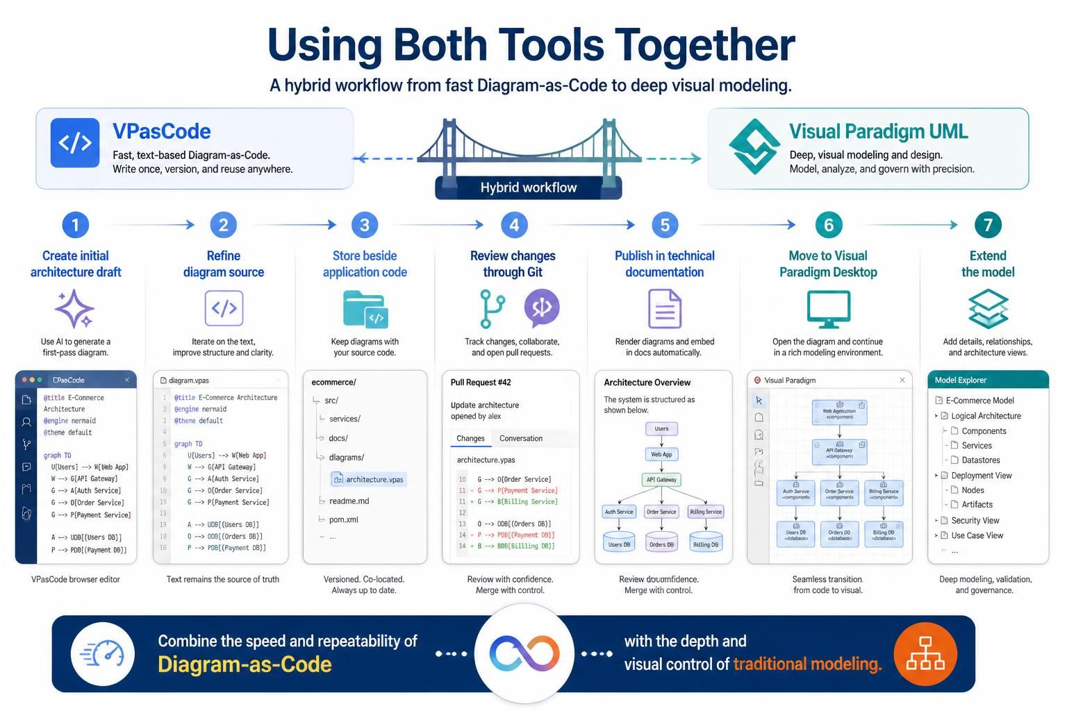
A combined workflow might look like this
-
Use an AI assistant or VPasCode to create an initial architecture draft.
-
Refine the diagram source in VPasCode.
-
Store the source alongside the application code.
-
Review changes through Git.
-
Publish the diagram in technical documentation.
-
Move the model into Visual Paradigm Desktop when deeper visual modeling is required.
-
Continue editing or extending the model through the appropriate Visual Paradigm environment.
This hybrid approach combines the speed and repeatability of Diagram-as-Code with the depth and visual control of a traditional modeling suite.
Practical Decision Guide
| Requirement | Recommended approach |
|---|---|
| Quick architecture sketch | VPasCode |
| Formal UML model with rich project context | Visual Paradigm UML |
| Git-based diagram review | VPasCode |
| Collaborative canvas workshop | Visual Paradigm UML |
| Natural-language diagram generation | VPasCode with AI |
| Detailed manual layout | Visual Paradigm UML |
| Markdown documentation | VPasCode with Mermaid |
| Formal PlantUML documentation | VPasCode |
| Enterprise model repository | Visual Paradigm UML |
| Rapidly changing service architecture | VPasCode |
| Broad stakeholder presentation | Visual Paradigm UML or exported VPasCode diagram |
| AI-generated first draft | VPasCode |
| Large structured modeling project | Visual Paradigm UML |
Recommended Working Practices
Regardless of the selected tool, effective diagrams should follow a few principles:
-
Define the purpose before choosing a diagram type.
-
Keep each diagram focused on one question.
-
Use consistent naming across diagrams and source code.
-
Clearly distinguish internal and external systems.
-
Avoid unnecessary implementation detail in stakeholder-facing diagrams.
-
Use layers, packages, or boundaries to control complexity.
-
Review generated diagrams for factual accuracy.
-
Store source files with the documentation they support.
-
Keep diagrams updated when the underlying system changes.
-
Prefer several focused diagrams over one unreadable overview.
For VPasCode specifically, teams should also:
-
Establish naming and styling conventions.
-
Keep source files small enough to review.
-
Use templates for recurring diagram types.
-
Select the diagram engine deliberately.
-
Treat AI output as a draft rather than an authoritative model.
-
Review rendered output as well as source code.
-
Keep generated diagrams synchronized with architecture changes.
Conclusion
Visual Paradigm UML and VPasCode represent two complementary approaches to software modeling.
Visual Paradigm UML emphasizes direct visual manipulation, structured models, detailed diagram control, and comprehensive project-based modeling. It is well suited to formal analysis, architecture work, requirements modeling, and collaborative visual design.
VPasCode emphasizes text-based diagram definitions, automatic rendering, browser access, AI assistance, multiple diagram engines, and version-control-friendly documentation. It is particularly effective for development teams that want diagrams to evolve alongside code and technical documentation.
The practical decision comes down to workflow preference and project requirements:
-
Choose Visual Paradigm UML when you need a rich graphical modeling environment.
-
Choose VPasCode when you want diagrams that can be written, reviewed, generated, and maintained as code.
-
Use both when a project benefits from rapid Diagram-as-Code iteration as well as deeper visual modeling.
The central advantage of VPasCode is not simply that it replaces drawing with typing. It changes diagrams into maintainable technical assets that can be generated, reviewed, versioned, reused, and connected to the rest of the software development lifecycle.
Relevant Visual Paradigm Articles and Posts
- VPasCode – Text-to-Diagram Platform: Overview of VPasCode’s browser-based editor, supported engines, live rendering, and AI features.
- VPasCode: Unified Diagram as Code Tool for PlantUML, Mermaid, D2, and Graphviz: Introduction to Visual Paradigm’s multi-engine Diagram-as-Code platform.
- Mastering VPasCode: The Ultimate Guide to AI-Powered Diagram-as-Code with Multi-Engine Support: Detailed guide to VPasCode, AI diagram generation, engine selection, and workflow integration.
- Comprehensive Guide to the Benefits of VPasCode Editor in Visual Paradigm’s Ecosystem: Explains VPasCode’s collaboration, documentation, AI, and model-to-code benefits.
- How the Visual Paradigm AI Chatbot and VPasCode Function as an Integrated Ecosystem for Diagramming: Describes the workflow from natural-language prompts to editable diagram code.
- Architecting the Future: The Ultimate Guide to Automated Living Documentation with Visual Paradigm and AI: Discusses AI-assisted diagrams and continuously maintained technical documentation.
- Turn Diagram Images into Editable Code with VPasCode AI: Covers generating editable diagram code from screenshots, existing diagrams, and hand-drawn references.
- Visual Paradigm VPasCode Features: Highlights AI generation, AI modification, diagnostics, translation, themes, and real-time rendering.
- Visualize Zig Code as UML Class Diagrams with VPasCode: Demonstrates the use of VPasCode for code-based diagram generation.
- Beyond the Code: How Strategic UML Modeling Bridges the Gap Between Developers and Stakeholders: Explores how UML supports communication between technical and nontechnical audiences.
Related posts:
 Visual Paradigm AI: Generate Professional UML Use Case Diagrams from Text in Seconds
 GourmetReserve Development Simplified: Transforming Requirements with the Best AI-Powered Use Case Modeling Studio
 The Best AI-Powered Database Modeling Tool for Designing Hospital Systems: Visual Paradigm Online
 Automating Student Record System Analysis: From Raw Text to Class Models with Visual Paradigm