
Introduction
In the complex world of software engineering, understanding how different parts of a system interact is crucial for building robust, maintainable applications. UML Component Diagrams serve as a powerful tool for modeling the physical aspects of object-oriented systems. They provide a high-level view of how components are organized, how they interact through interfaces, and how they depend on one another.
Whether you are architecting a new microservices-based application, documenting an existing legacy system, or planning a database migration, component diagrams offer clarity and structure. This guide will walk you through the fundamental concepts, notation, relationships, and practical applications of UML Component Diagrams, leveraging modern tools like Visual Paradigm’s AI Chatbot and VPasCode to streamline your modeling process.
What is a Component Diagram?
UML Component diagrams are used in modeling the physical aspects of object-oriented systems. They are essential for:
-
Visualizing the static implementation view of a system.
-
Specifying component-based systems.
-
Documenting architecture for stakeholders and development teams.
-
Constructing executable systems through forward and reverse engineering.
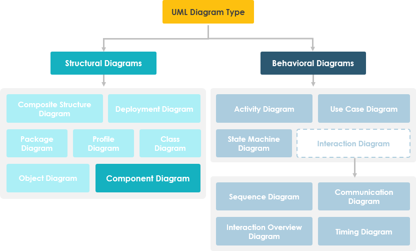
Component diagrams are essentially class diagrams that focus on a system’s components rather than individual classes. They help break down complex systems into manageable, modular parts.
Learn UML Faster, Better and Easier
Are you looking for a Free UML tool for learning UML faster, easier and quicker? Visual Paradigm Community Edition is a UML software that supports all UML diagram types. It is an international award-winning UML modeler, and yet it is easy-to-use, intuitive & completely free.
Free Download
Component Diagram at a Glance
A component diagram breaks down the actual system under development into various high levels of functionality. Each component is responsible for one clear aim within the entire system and only interacts with other essential elements on a need-to-know basis.
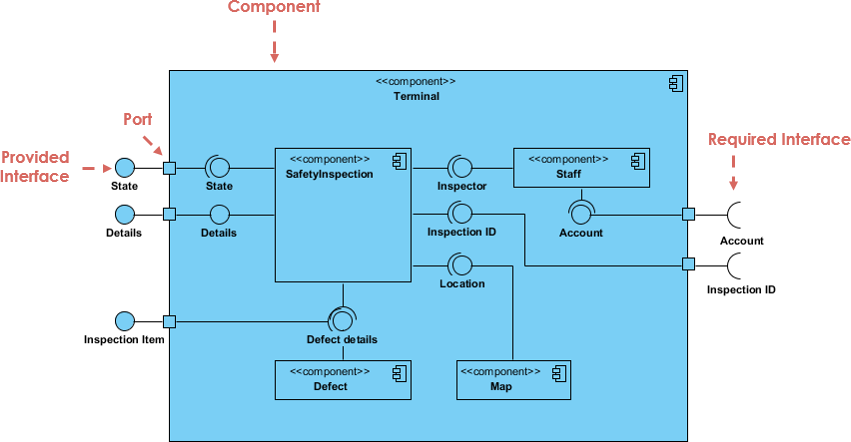
The example above shows the internal components of a larger component:
-
Required Interfaces: The data (account and inspection ID) flows into the component via the port on the right-hand side and is converted into a format the internal components can use. The interfaces on the right are known as required interfaces, which represent the services the component needs in order to carry out its duty.
-
Provided Interfaces: The data then passes to and through several other components via various connections before it is output at the ports on the left. Those interfaces on the left are known as provided interfaces, which represent the services delivered by the exhibiting component.
-
Encapsulation: It is important to note that the internal components are surrounded by a large ‘box’ which can be the overall system itself (in which case there would not be a component symbol in the top right corner) or a subsystem or component of the overall system (in this case the ‘box’ is a component itself).
Basic Concepts of Component Diagram
A component represents a modular part of a system that encapsulates its contents and whose manifestation is replaceable within its environment. In UML 2, a component is drawn as a rectangle with optional compartments stacked vertically. A high-level, abstracted view of a component in UML 2 can be modeled as:
-
A rectangle with the component’s name.
-
A rectangle with the component icon.
-
A rectangle with the stereotype text and/or icon.

Architect Your Modular Systems with AI
Component diagrams visualize the modular parts and physical manifestation of your system. Using Visual Paradigm’s AI Chatbot, you can instantly brainstorm system architectures, identify provided/required interfaces, and generate initial component diagrams through a simple conversational interface.
NOW AVAILABLE: AI Chatbot – Your Design Partner
Simply describe your modules, microservices, or database structures to the chatbot. It will help you define:
-
Modular Boundaries: Identify which parts of your system should be encapsulated as components.
-
Dependency Mapping: Visualize how different executables and libraries interact within your release.
Chat with AI Now
Learn more about our AI-driven modeling ecosystem:
AI Component Guide All AI Tools
Interfaces
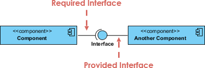
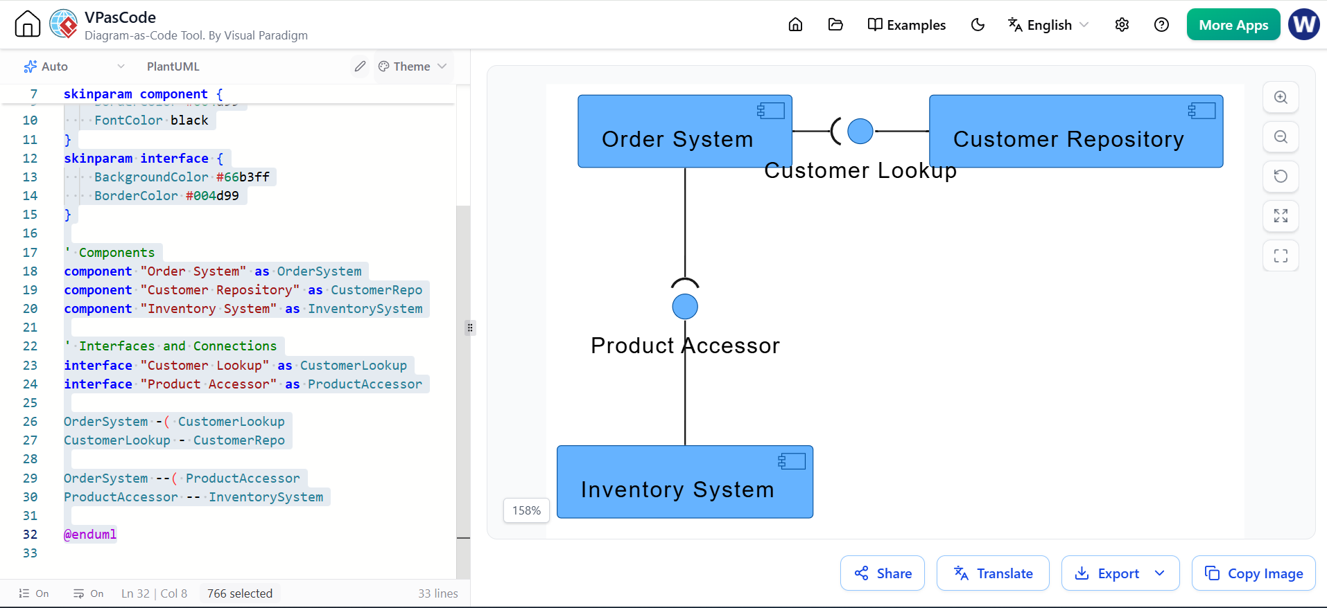
Interfaces define the contract between components. In the example below, two types of component interfaces are shown:
-
Provided Interface: Symbols with a complete circle at their end (often called a “lollipop”) represent an interface that the component provides. This is shorthand for a realization relationship of an interface classifier.
-
Required Interface: Symbols with only a half circle at their end (a.k.a. sockets) represent an interface that the component requires. In both cases, the interface’s name is placed near the interface symbol itself.
Component Diagram Example – Using Interface (Order System)
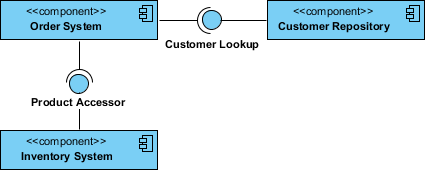
PlantUML Equivalent:
@startuml
skinparam componentStyle uml2
skinparam BackgroundColor white
skinparam DefaultFontName Arial

' Style configuration to match the blue colors
skinparam component {
    BackgroundColor #66b3ff
    BorderColor #004d99
    FontColor black
}
skinparam interface {
    BackgroundColor #66b3ff
    BorderColor #004d99
}

' Components
component "Order System" as OrderSystem
component "Customer Repository" as CustomerRepo
component "Inventory System" as InventorySystem

' Interfaces and Connections
interface "Customer Lookup" as CustomerLookup
interface "Product Accessor" as ProductAccessor

OrderSystem -( CustomerLookup
CustomerLookup - CustomerRepo

OrderSystem --( ProductAccessor
ProductAccessor -- InventorySystem

@enduml
Subsystems
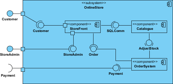
The subsystem classifier is a specialized version of a component classifier. Because of this, the subsystem notation element inherits all the same rules as the component notation element. The only difference is that a subsystem notation element has the keyword <<subsystem>> instead of <<component>>.
Ports
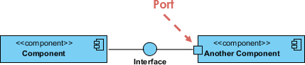
Ports are represented using a square along the edge of the system or a component. A port is often used to help expose required and provided interfaces of a component, acting as a specific interaction point.
Relationships
Graphically, a component diagram is a collection of vertices and arcs and commonly contains components, interfaces, and various relationships such as dependency, aggregation, constraint, generalization, association, and realization. It may also contain notes and constraints.
| Relationships | Notation | Description |
|---|---|---|
| Association |  |
An association specifies a semantic relationship that can occur between typed instances. It has at least two ends represented by properties, each of which is connected to the type of the end. |
| Composition |  |
Composite aggregation is a strong form of aggregation that requires a part instance be included in at most one composite at a time. If a composite is deleted, all of its parts are normally deleted with it. |
| Aggregation |  |
A kind of association that has one of its ends marked as shared aggregation, meaning that it has a shared aggregation. |
| Constraint | 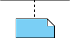 |
A condition or restriction expressed in natural language text or in a machine-readable language for the purpose of declaring some of the semantics of an element. |
| Dependency |  |
A dependency signifies that a single or a set of model elements requires other model elements for their specification or implementation. The depending elements are semantically or structurally dependent on the supplier element(s). |
| Generalization |  |
A taxonomic relationship between a more general classifier and a more specific classifier. Each instance of the specific classifier is also an indirect instance of the general classifier, inheriting its features. |
Practical Applications
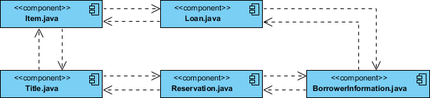
1. Modeling Source Code
-
Either by forward or reverse engineering, identify the set of source code files of interest and model them as components stereotyped as
<<file>>. -
For larger systems, use packages to show groups of source code files.
-
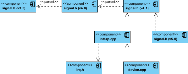
Consider exposing a tagged value indicating information such as the version number of the source code file, its author, and the date it was last changed. Use tools to manage the value of this tag.
-
Model the compilation dependencies among these files using dependencies. Again, use tools to help generate and manage these dependencies.
Component Example – Java Source Code
Component Diagram Example – C++ Code with Versioning
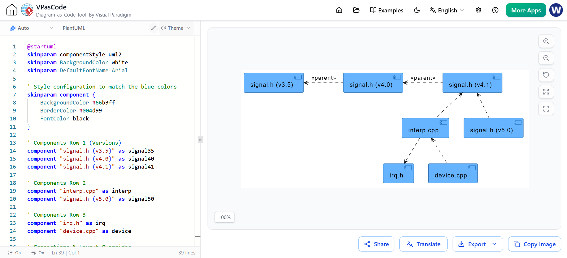
PlantUML Equivalent for Source Code Modeling:
@startuml
skinparam componentStyle uml2
skinparam BackgroundColor white
skinparam DefaultFontName Arial

' Style configuration to match the blue colors
skinparam component {
    BackgroundColor #66b3ff
    BorderColor #004d99
    FontColor black
}

' Components Row 1 (Versions)
component "signal.h (v3.5)" as signal35
component "signal.h (v4.0)" as signal40
component "signal.h (v4.1)" as signal41

' Components Row 2
component "interp.cpp" as interp
component "signal.h (v5.0)" as signal50

' Components Row 3
component "irq.h" as irq
component "device.cpp" as device

' Connections & Layout Overrides
' Top Row left-pointing parents
signal40 .left.> signal35 : <>
signal41 .left.> signal40 : <>

' Vertical dependencies
interp .up.> signal41
signal50 .up.> signal41

interp .down.> irq
device .up.> interp

@enduml
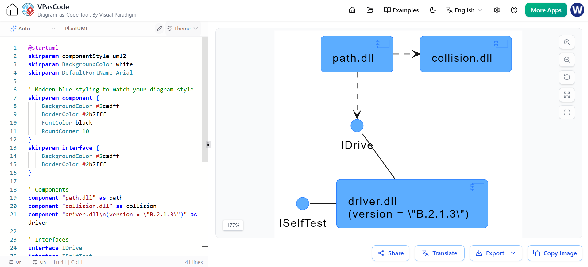
 2. Modeling an Executable Release
-
Identify the set of components you’d like to model. Typically, this will involve some or all the components that live on one node, or the distribution of these sets of components across all the nodes in the system.
-
Consider the stereotype of each component in this set. For most systems, you’ll find a small number of different kinds of components (such as executables, libraries, tables, files, and documents). You can use UML’s extensibility mechanisms to provide visual cues for these stereotypes.
-
For each component in this set, consider its relationship to its neighbors. Most often, this will involve interfaces that are exported (realized) by certain components and then imported (used) by others. If you want to expose the seams in your system, model these interfaces explicitly. If you want your model at a higher level of abstraction, elide these relationships by showing only dependencies among the components.
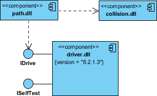
PlantUML Equivalent for Executable Release:
@startuml
skinparam componentStyle uml2
skinparam BackgroundColor white
skinparam DefaultFontName Arial

' Modern blue styling to match your diagram style
skinparam component {
    BackgroundColor #5cadff
    BorderColor #2b7fff
    FontColor black
    RoundCorner 10
}
skinparam interface {
    BackgroundColor #5cadff
    BorderColor #2b7fff
}

' Components
component "path.dll" as path
component "collision.dll" as collision
component "driver.dll\n(version = \"B.2.1.3\")" as driver

' Interfaces
interface IDrive
interface ISelfTest

' Layout & Clean Connections
path .right.> collision

' Use hidden layouts to force vertical stacking of interfaces
IDrive -[hidden]down- ISelfTest

' Connect driver to its interfaces cleanly on the left
driver -left- IDrive
driver -left- ISelfTest

' Clean, straight vertical dependency line
path .down.> IDrive

@enduml
 3. Modeling a Physical Database
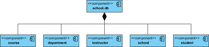
-
Identify the classes in your model that represent your logical database schema.
-
Select a strategy for mapping these classes to tables. You will also want to consider the physical distribution of your databases. Your mapping strategy will be affected by the location in which you want your data to live on your deployed system.
-
To visualize, specify, construct, and document your mapping, create a component diagram that contains components stereotyped as
<<table>>. -
Where possible, use tools to help you transform your logical design into a physical design.
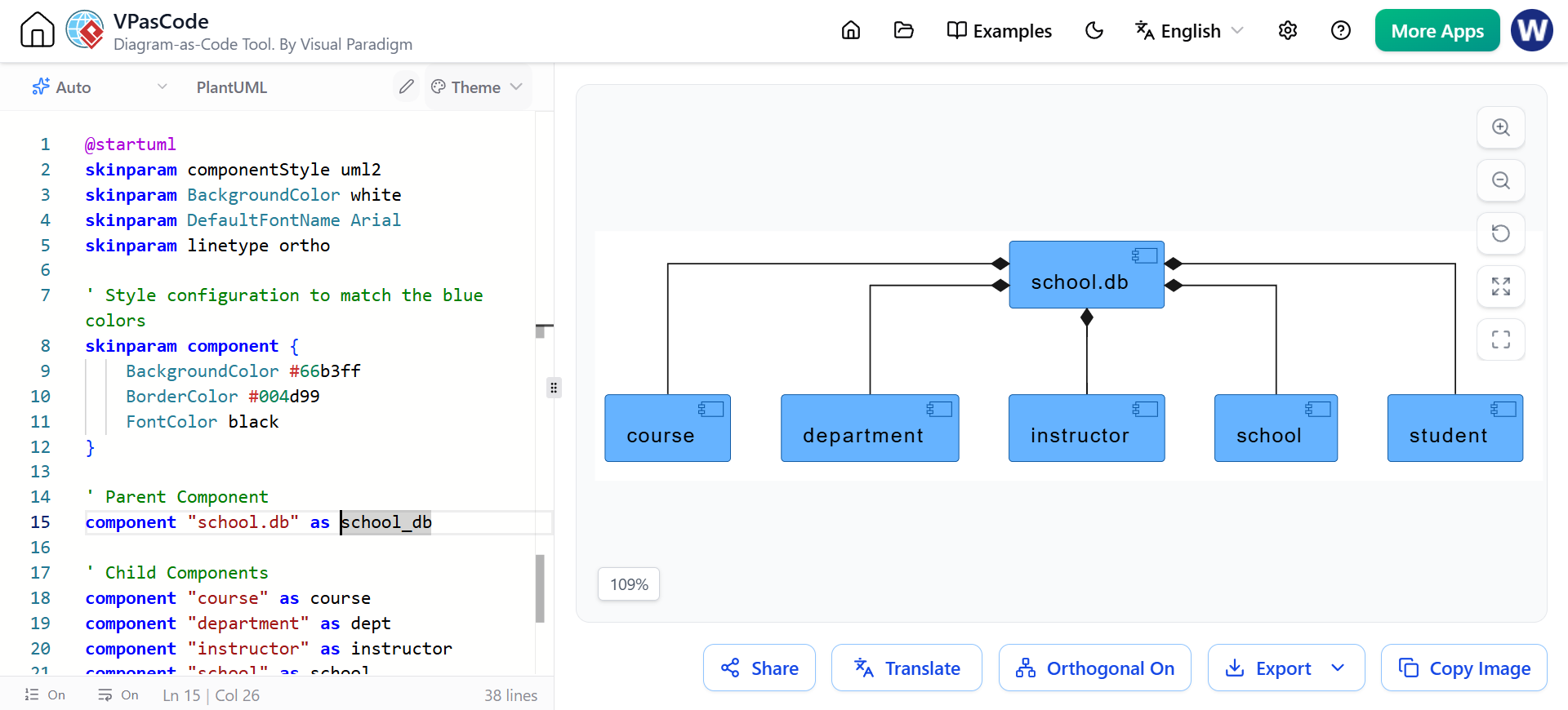
PlantUML Equivalent for Physical Database:
@startuml
skinparam componentStyle uml2
skinparam BackgroundColor white
skinparam DefaultFontName Arial
skinparam linetype ortho

' Style configuration to match the blue colors
skinparam component {
    BackgroundColor #66b3ff
    BorderColor #004d99
    FontColor black
}

' Parent Component
component "school.db" as school_db

' Child Components
component "course" as course
component "department" as dept
component "instructor" as instructor
component "school" as school
component "student" as student

' Hidden links to enforce the horizontal alignment row
course -[hidden]right- dept
dept -[hidden]right- instructor
instructor -[hidden]right- school
school -[hidden]right- student

' Composition Relationships (Black Diamond)
school_db *-- course
school_db *-- dept
school_db *-- instructor
school_db *-- school
school_db *-- student

@endif
Conclusion
UML Component Diagrams are indispensable for architects and developers who need to communicate the structural integrity of a system. By focusing on components, interfaces, and their relationships, these diagrams provide a clear blueprint for how software modules interact, depend on, and integrate with one another.
With the advent of AI-driven tools like Visual Paradigm’s AI Chatbot and code-based modeling with VPasCode and PlantUML, creating and maintaining these diagrams has become more efficient and accessible. Whether you are modeling source code dependencies, planning executable releases, or designing physical database schemas, component diagrams offer the clarity needed to build scalable and maintainable systems.
Start leveraging these tools today to enhance your architectural documentation and streamline your development workflow.
Related posts:
 How to Localize Technical Manuals: Translate Text in Image Files for Global Teams
 🚀 Simplify Complex Workflows with Visual Paradigm AI Sequence Diagram Tool!
 AI Animated Banner Generator Review: The Ultimate Tool for Instant Marketing Visuals
 Comprehensive Guide: Developing As-Is and To-Be Business Processes with BPMN