
Introduction
In software engineering, bridging the gap between stakeholder needs and technical implementation is often the most challenging phase of development. The Use Case Driven Approach offers a structured, iterative methodology to solve this problem. By focusing on how users interact with the system to achieve specific goals, this approach ensures that requirements are clear, testable, and directly traceable to design artifacts.
This guide provides a complete walkthrough of the Use Case Driven Approach, moving from high-level requirements to detailed design. We will use a single running example—an Online Order Management System—to illustrate every stage, ensuring consistency and clarity throughout the process.
The Methodology Overview
The Use Case Driven Approach follows a natural top-down progression. Each stage refines the previous one, adding precision and reducing ambiguity.
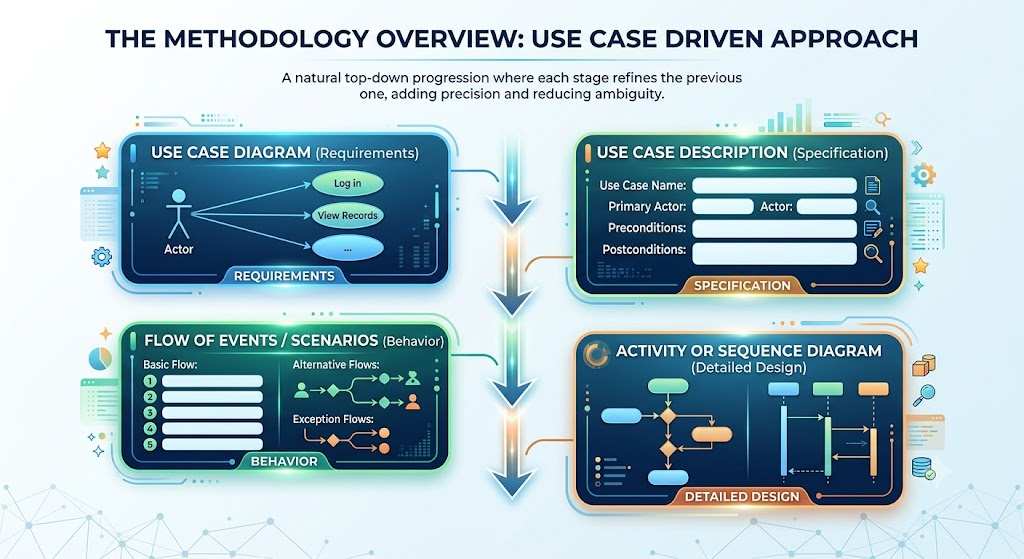
Why This Order Matters?
-
Use Case Diagram: Provides a complete inventory of capabilities and scope. It is fast to scan and ideal for stakeholder agreement on what the system does.
-
Use Case Description: Removes ambiguity by pinning down preconditions, postconditions, actors, and priority. It “freezes” the behavior contract.
-
Flow of Events: Turns the contract into concrete, testable steps. This serves as the raw material for both test cases and technical design.
-
Activity/Sequence Diagram: Acts as the bridge to code. It identifies participating objects, their responsibilities, message exchanges, and exact branching rules.
Stage 1: Use Case Diagram (Requirements)
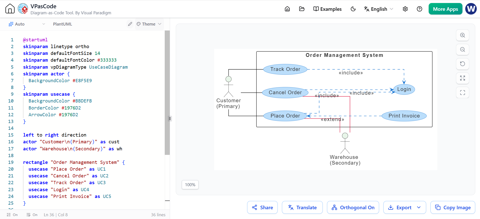
The Use Case Diagram captures who interacts with the system (actors) and what they can do (use cases), along with the relationships between them.
Key Concepts
-
Primary Actor: Initiates the use case (placed on the left).
-
Secondary Actor: Supports the system or receives notifications (placed on the right).
-
System Boundary: The rectangle defining the scope of the system.
-
<<include>>: Represents mandatory shared behavior. If Use Case A includes Use Case B, B must happen for A to complete. -
<<extend>>: Represents optional behavior. Use Case B extends Use Case A only under specific conditions.
Example: Online Order Management System
@startuml
skinparam linetype ortho
skinparam defaultFontSize 14
skinparam defaultFontColor #333333
skinparam vpDiagramType UseCaseDiagram
skinparam actor {
  BackgroundColor #E8F5E9
}
skinparam usecase {
  BackgroundColor #BBDEFB
  BorderColor #1976D2
  ArrowColor #1976D2
}

left to right direction
actor "Customer\n(Primary)" as cust
actor "Warehouse\n(Secondary)" as wh

rectangle "Order Management System" {
  usecase "Place Order" as UC1
  usecase "Cancel Order" as UC2
  usecase "Track Order" as UC3
  usecase "Login" as UC4
  usecase "Print Invoice" as UC5
}

cust -[#black]- UC1
cust -[#black]- UC2
cust -[#black]- UC3
UC1 -[#crimson]- wh
UC2 -[#crimson]- wh
UC1 ...> UC4 : <<include>>
UC2 ...> UC4 : <<include>>
UC3 ...> UC4 : <<include>>
UC1 <... UC5 : <<extend>>
@enduml
Analysis of the Diagram:
-
The Customer initiates placing, canceling, and tracking orders.
-
The Warehouse is involved in placing and canceling orders (likely for inventory updates).
-
Login is included in Place, Cancel, and Track Orders, meaning authentication is mandatory for these actions.
-
Print Invoice extends Place Order, meaning it is an optional step that may occur after an order is placed.
Stage 2: Use Case Description (Specification)
A diagram names the use cases but lacks detail. The Use Case Description table specifies the precise contract for each use case.
Example: UC-01 Place Order
| Field | Value |
|---|---|
| Use Case ID | UC-01 |
| Name | Place Order |
| Primary Actor | Customer |
| Secondary Actor | Warehouse |
| Preconditions | Customer is logged in; cart contains at least one item; items are in stock |
| Postconditions (Success) | Order is persisted with status confirmed; payment is captured; tracking number issued |
| Postconditions (Failure) | No order created; cart unchanged; user informed of reason |
| Main Flow | → See Stage 3 |
| Alternative / Exception Flows | Insufficient stock; payment declined |
| Priority | High |
Purpose: This stage defines what must be true before the use case runs (preconditions) and what must hold after (postconditions), establishing a clear success/failure criteria.
Stage 3: Flow of Events (Scenarios)
This is the behavioral heart of the approach. The “Place Order” use case expands into a scenario script—a sequence of numbered steps written before any detailed design diagrams exist.
Main Success Scenario (Basic Flow)
-
Customer logs in.
-
Customer submits the cart with the selected items.
-
System validates cart contents and stock availability.
-
System charges the total through the payment gateway.
-
System saves the order with status
confirmed. -
System returns an order confirmation with an order ID.
-
System notifies the Warehouse to pick, pack, and ship.
Alternative Scenarios
-
3a. Insufficient Stock: System reports the unavailable items and returns to cart.
-
4a. Payment Declined: System informs the customer and does not create the order.
Key Convention: Each scenario maps directly to a step in the description. These flows become the basis for the Activity and Sequence diagrams in the next stage.
Stage 4: Detailed Design (Sequence & Activity Diagrams)
At this stage, you choose the notation based on what aspect of the system you wish to emphasize.
-
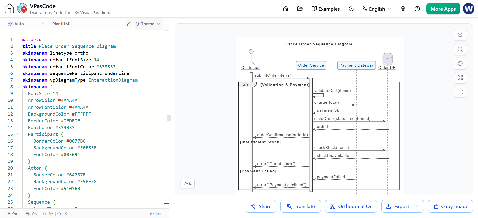
Sequence Diagram: Emphasizes lifelines, message order, and responsibilities between objects. Ideal for discovering classes and methods.
-
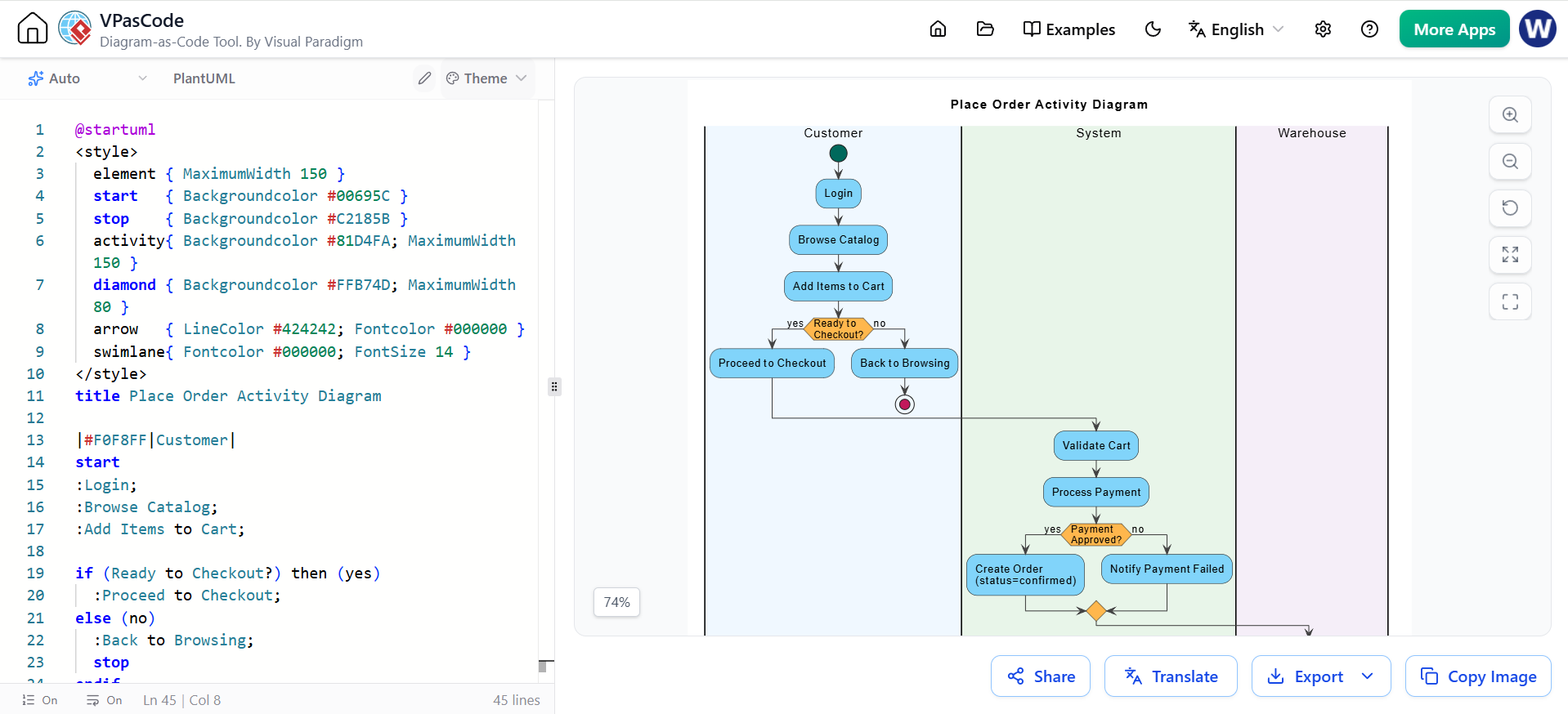
Activity Diagram: Emphasizes control flow and decisions through lanes/parties. Ideal for documenting processes and role responsibilities.
4A. Sequence Diagram (Interaction Perspective)
@startuml
title Place Order Sequence Diagram
skinparam linetype ortho
skinparam defaultFontSize 14
skinparam defaultFontColor #333333
skinparam sequenceParticipant underline
skinparam vpDiagramType InteractionDiagram
skinparam {
  FontSize 14
  ArrowColor #4A4A4A
  ArrowFontColor #4A4A4A
  BackgroundColor #FFFFFF
  BorderColor #DEDEDE
  FontColor #333333
  Participant {
    BorderColor #0077B6
    BackgroundColor #F0F8FF
    FontColor #005691
  }
  Actor {
    BorderColor #6A057F
    BackgroundColor #F5EEF8
    FontColor #510363
  }
  Sequence {
    ArrowThickness 2
    LifeLineBorderColor #444444
    LifeLineBackgroundColor #F7F7F7
    BoxBorderColor #AAAAAA
    BoxBackgroundColor #FFFFFF
    BoxFontColor #333333
  }
}

actor "Customer" as USR
participant "Order Service" as OS
participant "Payment Gateway" as PG
database "Order DB" as DB

activate USR
USR -> OS : submitOrder(items)
activate OS
alt Validation & Payment
  OS -> OS : validateCart(items)
  OS -> PG : charge(total)
  activate PG
  PG --> OS : paymentOk
  deactivate PG
  OS -> DB : saveOrder(status=confirmed)
  activate DB
  DB --> OS : orderId
  deactivate DB
  OS --> USR : orderConfirmation(orderId)
else Insufficient Stock
  OS -> DB : checkStock(items)
  activate DB
  DB --> OS : stockUnavailable
  deactivate DB
  OS --> USR : error("Out of stock")
else Payment Failed
  PG --> OS : paymentFailed
  OS --> USR : error("Payment declined")
end
deactivate OS
@enduml
Key Concepts:
-
Synchronous Calls: Solid arrows (
->). -
Replies: Dashed arrows (
-->). -
Activation Bars: Show the lifespan of an object’s processing.
-
altCombined Fragment: Wraps the three scenarios (Success, Insufficient Stock, Payment Failure), directly mirroring the Flow of Events from Stage 3.
4B. Activity Diagram (Process Perspective)
@startuml
<style>
  element { MaximumWidth 150 }
  start   { Backgroundcolor #00695C }
  stop    { Backgroundcolor #C2185B }
  activity{ Backgroundcolor #81D4FA; MaximumWidth 150 }
  diamond { Backgroundcolor #FFB74D; MaximumWidth 80 }
  arrow   { LineColor #424242; Fontcolor #000000 }
  swimlane{ Fontcolor #000000; FontSize 14 }
</style>
title Place Order Activity Diagram

|#F0F8FF|Customer|
start
:Login;
:Browse Catalog;
:Add Items to Cart;

if (Ready to Checkout?) then (yes)
  :Proceed to Checkout;
else (no)
  :Back to Browsing;
  stop
endif

|#E8F5E9|System|
:Validate Cart;
:Process Payment;

if (Payment Approved?) then (yes)
  :Create Order (status=confirmed);
else (no)
  :Notify Payment Failed;
endif

|#F5EEF8|Warehouse|
if (Payment Approved?) then (yes)
  :Pick & Pack Items;
  :Ship Order;
  :Send Tracking Number;
  stop
else (no)
  stop
endif
@enduml
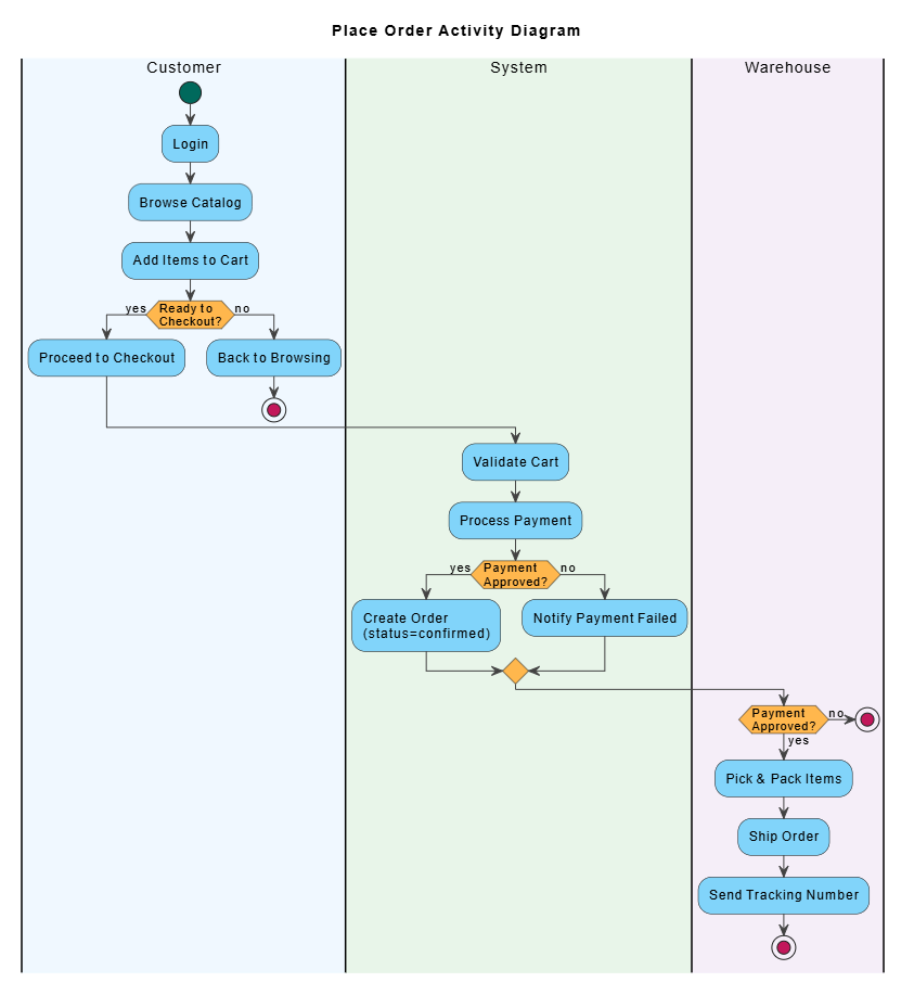 Key Concepts:
-
Swimlanes: Assign each action to the responsible party (Customer, System, Warehouse).
-
Decision Nodes:
if/then/else/endifstructures encode branching scenarios. -
Start/Stop Markers: Delimit the beginning and end of the process.
Key PlantUML Takeaways
To effectively model this approach using PlantUML, remember the following syntax essentials:
-
-
Use
usecasefor functions. -
Use
...>for<<include>>relationships. -
Use
<...for<<extend>>relationships. -
Use
rectangle "System Name" {}to define the system boundary.
-
-
Sequence Diagrams:
-
Define participants using
actor,participant, ordatabase. -
Use
->for synchronous calls and-->for replies. -
Use
activateanddeactivateto show object lifespans. -
Use
alt,else, andendfor combined fragments representing alternative flows.
-
-
Activity Diagrams:
-
Use
|#color|LaneName|to define swimlanes. -
Use
:action;for activities. -
Use
if/else/endiffor decision nodes. -
Use
startandstopto mark process boundaries.
-
Conclusion
The Use Case Driven Approach is more than just a documentation technique; it is a framework for progressive refinement. By starting with the big picture (Use Case Diagram) and drilling down into specific behaviors (Flow of Events) and technical interactions (Sequence/Activity Diagrams), teams can ensure that every line of code traces back to a verified user need.
This method reduces the risk of miscommunication between stakeholders and developers, facilitates easier testing through clear scenarios, and results in a robust, user-centric system design. Whether you are building a simple e-commerce platform or a complex enterprise system, adhering to this structured progression will lead to clearer requirements and higher-quality software.
Related posts:
 Comprehensive Guide: From Problem Statement to Class Diagram, ERD, and Database Modeling with Visual Paradigm
 Visual Paradigm’s AI‑Powered ERD Generator
 How Visual Paradigm’s AI Diagram Generation Turns Your Ideas into Professional UML & BPMN Diagrams in Seconds
 Why Teams Are Switching to Visual Paradigm: Powerful Modeling Meets Cutting-Edge AI