
Introduction
In the complex world of software engineering, understanding what a system does is only half the battle; understanding how it does it over time is where true architectural clarity emerges. While static diagrams define structure, they often fail to capture the dynamic nature of software behavior—the messages passed, the order of operations, and the critical timing of interactions.
Enter the UML Sequence Diagram. As an interaction diagram, it visualizes objects or actors along vertical lifelines and maps their message exchanges horizontally, ordered chronologically from top to bottom. It answers a deceptively simple yet profound question: “Who talks to whom, in what order, and what happens next?”
This guide explores why sequence diagrams are among the most widely used tools in the industry, who benefits from them, and how they integrate with other UML artifacts to create a complete system model. Using a practical e-commerce checkout scenario, we will demonstrate how to move from high-level scope to detailed behavioral modeling, ensuring that your technical designs are both robust and understandable.
1. When to Use a Sequence Diagram
Sequence diagrams are not a one-size-fits-all solution. They shine specifically when time order and interaction are the primary concerns, rather than static structure or actor scope.
| Situation | Why a Sequence Diagram Fits |
|---|---|
| Designing a new use case or feature | Allows exploration of how collaborating objects fulfill a behavior before writing code. |
| Defining communication protocols | Ideal for mapping request–response flows, API calls, or messaging between systems/services. |
| Managing concurrency and ordering | Essential when asynchronous calls, parallel branches, and strict timing are core concerns. |
| Tracing a single scenario end-to-end | Provides a concrete path through a system; the diagram is the trace. |
| Documenting existing behavior | Useful for reverse-engineering legacy flows, onboarding new developers, or documenting integrations. |
| Debugging and test design | Helps identify which objects interact, aiding in the design of tests and stubs around those interactions. |
| Design reviews and walkthroughs | Offers a concrete, time-ordered picture that makes behavioral review practical and tangible. |
2. Who Uses Sequence Diagrams?
Sequence diagrams serve as a common language across various technical and business roles:
-
System/Software Architects: Model end-to-end interactions across components and services to validate architectural decisions (e.g., synchronous vs. asynchronous calls).
-
Application Developers: Use them as a design blueprint before coding non-trivial workflows and as living documentation of call sequences.
-
Technical Leads / Senior Engineers: Facilitate design reviews using sequence diagrams to discuss behavior at a granular level.
-
QA / Test Engineers: Derive integration and end-to-end test cases and identify dependency points that require mocking.
-
Project Managers & Business Analysts: Translate user journeys into soft requirements and cross-check that software behavior aligns with business processes.
-
System Integrators & Solution Consultants: Model handoffs between multiple vendored systems, APIs, and third-party services (such as payment gateways).
3. Why Sequence Diagrams Are Industry Staples
The sequence diagram’s popularity stems from its alignment with human cognition and software reality:
-
Mirrors Natural Narration: Humans naturally describe workflows as sequences (“click checkout,” “save order,” “charge card”). The diagram is the direct visual form of this narration.
-
Captures Time and Causality: Unlike class or component diagrams, sequence diagrams explicitly model the order of operations, which is often the most critical detail in a system.
-
Intuitive and Low-Friction: Lifelines and messages are easy to read, allowing stakeholders to follow scenarios without deep UML training.
-
Scenario-Driven Focus: Instead of modeling every possible relationship upfront, it focuses on one concrete use case, making it fast to produce and easy to validate.
-
Excellent Tooling Support: Translates naturally to modern build artifacts like API call graphs and can be stored as code (e.g., PlantUML), keeping documentation close to the source.
-
Scalable Complexity: Features like
alt/opt/loopfragments and activation bars allow a single diagram to express branches, options, and repetition without losing readability.
4. Case Study: E-Commerce Checkout System
To anchor these concepts, let’s examine a concrete example: an online checkout flow.
The Scenario:
A customer submits a checkout with their shopping cart. The Order Service validates it, reserves inventory, charges the payment gateway, and—on approval—confirms and persists the order. The customer receives confirmation or an appropriate error.
Step 1: Define Scope with a Use Case Diagram
Before detailing interactions, we must model the scope and actors. The Use Case Diagram tells us who interacts with the system and what they can do, defining the boundary without specifying how.
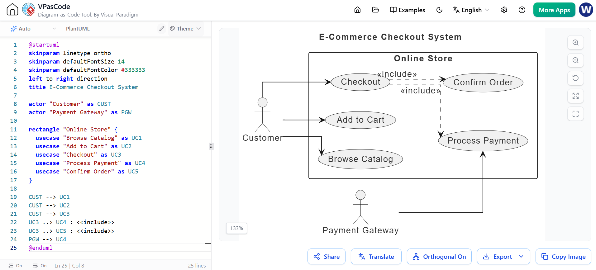
@startuml
skinparam linetype ortho
skinparam defaultFontSize 14
skinparam defaultFontColor #333333
left to right direction
title E-Commerce Checkout System

actor "Customer" as CUST
actor "Payment Gateway" as PGW

rectangle "Online Store" {
  usecase "Browse Catalog" as UC1
  usecase "Add to Cart" as UC2
  usecase "Checkout" as UC3
  usecase "Process Payment" as UC4
  usecase "Confirm Order" as UC5
}

CUST --> UC1
CUST --> UC2
CUST --> UC3
UC3 ..> UC4 : <<include>>
UC3 ..> UC5 : <<include>>
PGW --> UC4
@enduml
Step 2: Model Interaction with a Sequence Diagram
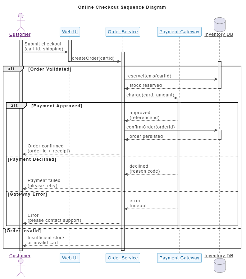
Taking the “Checkout” use case, we detail exactly how collaborating objects carry it out over time. This is the core of our behavioral model.
@startuml
skinparam linetype ortho
skinparam defaultFontSize 14
skinparam defaultFontColor #333333
skinparam sequenceParticipant underline
skinparam vpDiagramType InteractionDiagram
skinparam {
  FontSize 14
  ArrowColor #4A4A4A
  ArrowFontColor #4A4A4A
  BackgroundColor #FFFFFF
  BorderColor #DEDEDE
  FontColor #333333

  Participant {
    BorderColor #0077B6
    BackgroundColor #F0F8FF
    FontColor #005691
  }

  Actor {
    BorderColor #6A057F
    BackgroundColor #F5EEF8
    FontColor #510363
  }

  Sequence {
    ArrowThickness 2
    LifeLineBorderColor #444444
    LifeLineBackgroundColor #F7F7F7
    BoxBorderColor #AAAAAA
    BoxBackgroundColor #FFFFFF
    BoxFontColor #333333
  }
}

title Online Checkout Sequence Diagram

actor "Customer" as CUST
participant "Web UI" as UI
participant "Order Service" as OSVC
participant "Payment Gateway" as PGW
database "Inventory DB" as IDB

activate CUST
activate UI
CUST -> UI : Submit checkout\n(cart id, shipping)
activate OSVC
UI -> OSVC : createOrder(cartId)
deactivate UI
alt Order Validated
    activate IDB
    OSVC -> IDB : reserveItems(cartId)
    IDB --> OSVC : stock reserved
    deactivate IDB
    OSVC -> PGW : charge(card, amount)
    activate PGW
    alt Payment Approved
        PGW --> OSVC : approved\n(reference id)
        OSVC -> IDB : confirmOrder(orderId)
        activate IDB
        IDB --> OSVC : order persisted
        deactivate IDB
        OSVC --> CUST : Order confirmed\n(order id + receipt)
    else Payment Declined
        PGW --> OSVC : declined\n(reason code)
        OSVC --> CUST : Payment failed\n(please retry)
    else Gateway Error
        PGW --> OSVC : error\ntimeout
        OSVC --> CUST : Error\n(please contact support)
    end
    deactivate PGW
else Order Invalid
    OSVC --> CUST : Insufficient stock\nor invalid cart
end
deactivate OSVC
@enduml
Key Insights from the Sequence Diagram:
-
Exact Call Order:
createOrderoccurs beforereserveItems, which occurs beforecharge. -
Synchronous vs. Asynchronous: Activation bars show the “call stack,” indicating where the Order Service blocks while waiting for the Payment Gateway.
-
Branches and Errors:
altfragments capture approved, declined, gateway-error, and invalid-cart outcomes in one time-ordered view. -
Reply Channels: Dashed return messages carry results back to callers.
Step 3: Validate Structure with a Class Diagram
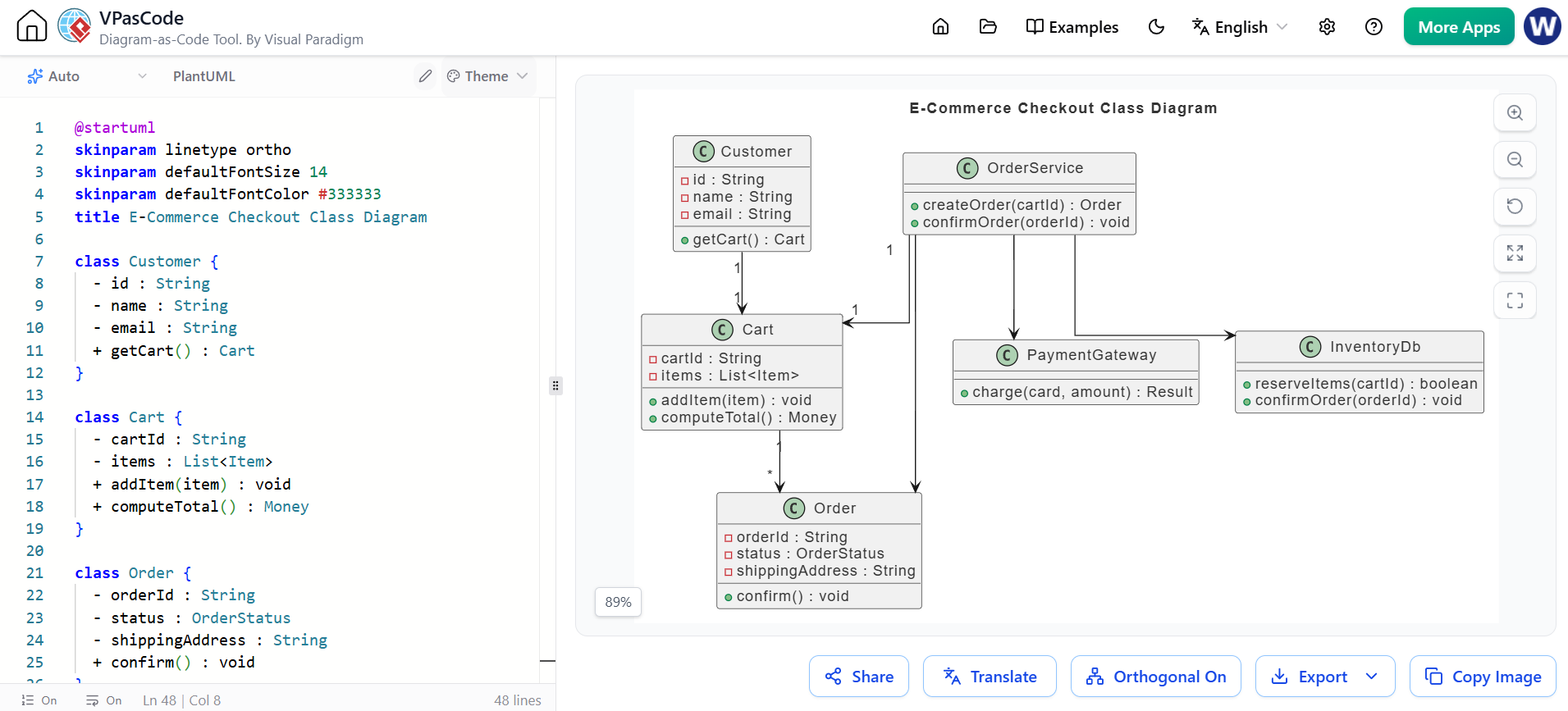
The sequence diagram shows how objects collaborate, but its lifelines represent instances of types that must exist. The Class Diagram provides the structural backbone—defining attributes, operations, and relationships.
@startuml
skinparam linetype ortho
skinparam defaultFontSize 14
skinparam defaultFontColor #333333
title E-Commerce Checkout Class Diagram

class Customer {
  - id : String
  - name : String
  - email : String
  + getCart() : Cart
}

class Cart {
  - cartId : String
  - items : List<Item>
  + addItem(item) : void
  + computeTotal() : Money
}

class Order {
  - orderId : String
  - status : OrderStatus
  - shippingAddress : String
  + confirm() : void
}

class OrderService {
  + createOrder(cartId) : Order
  + confirmOrder(orderId) : void
}

class PaymentGateway {
  + charge(card, amount) : Result
}

class InventoryDb {
  + reserveItems(cartId) : boolean
  + confirmOrder(orderId) : void
}

Customer "1" --> "1" Cart
Cart "1" --> "*" Order
OrderService "1" --> "1" Cart
OrderService --> Order
OrderService --> PaymentGateway
OrderService --> InventoryDb
@enduml
This ensures that the lifelines in the sequence diagram correspond to real, well-connected classes with the necessary operations.
5. Integrating Sequence Diagrams with Other UML Artifacts
A well-modeled system uses several UML diagrams together, as each captures a fundamental aspect of the system. The sequence diagram handles dynamic collaboration, while others cover structure, scope, and lifecycle.
| Companion Diagram | Aspect Captured | Why It Pairs with Sequence Diagrams |
|---|---|---|
| Use Case Diagram | Actor–system scope & goals | Defines which scenarios deserve a sequence diagram. Sequence diagrams refine use cases by detailing behavior. |
| Class Diagram | Static structure & types | Provides the lifeline types and operations referenced in the sequence. It is the static view; the sequence is the dynamic instance view. |
| State Machine Diagram | Lifecycle of a single object | Shows how an object (e.g., Order) moves between states. The sequence diagram shows the messages that trigger these transitions. |
| Activity Diagram | Overall flow, parallelism, decisions | Provides a high-level business/process flow. The sequence diagram zooms into the technical message-level interactions of specific steps. |
| Component Diagram | Physical/software building blocks | Shows deployed black-box components. The sequence diagram reveals the message traffic between them, exposing coupling. |
| Deployment Diagram | Hardware/nodes & deployment | Validates network latency and physical service location, complementing the logical interactions in the sequence. |
| Communication Diagram | Interaction structure-first | An alternative view of the sequence diagram, swapping “time order” for “link structure.” Highlights direct connections between objects. |
| Timing Diagram | Precise timing constraints | Complements the sequence diagram when real-time guarantees (timeouts, deadlines) are critical. |
The Key Insight: Composition Matters
-
Use Case + Sequence: Defines what to build and how it behaves.
-
Class/Component + Sequence: Defines what exists and how it talks. Together, they form the complete static + dynamic picture.
-
State Machine + Sequence: Defines possible lifecycle states and the messages that move an object between them.
-
Activity + Sequence: Defines the business process and the technical protocol for each step.
No single UML diagram is sufficient. The sequence diagram carries the core behavioral load, but it flourishes best when combined with use-case, class, state, and component diagrams.
6. Best Practices for Effective Sequence Diagrams
-
Start with a Use Case: Model one scenario per diagram. Do not overload a single diagram with every possible path.
-
Limit Participants: Keep lifelines to 3–7 participants. Too many destroy readability; decompose into nested interactions if necessary.
-
Show Activation Bars: These communicate the nesting of calls (the “call stack”) at a glance.
-
Use Control Fragments: Leverage
alt(alternative),opt(optional), andloopfragments to express branches and iteration without drawing separate diagrams. -
Choose Arrows Deliberately: Use solid arrows for synchronous calls and dashed open arrows for asynchronous replies.
-
Keep It Source-Controlled: Embed diagram code (e.g., PlantUML) next to the code it documents to prevent documentation drift.
-
Ensure Scenario Completeness: Include the success path plus realistic failure/error paths so testers and reviewers see the full behavior.
Conclusion
The UML sequence diagram is a cornerstone of effective software modeling because it captures the dimension that matters most in real-world applications: time-ordered collaboration. It is intuitive, quick to produce, and uniquely capable of expressing synchronous/asynchronous flows, branching logic, and error handling.
However, its true power is unlocked only when used in composition. By pairing sequence diagrams with use case diagrams for scope, class diagrams for structure, state machines for lifecycle, and activity diagrams for process flow, teams can transform a simple checkout flow into a comprehensive, navigable model of the entire system. From business scope down to the message protocol between components, this integrated approach ensures clarity, reduces ambiguity, and drives successful software delivery.
Related posts:
 Comprehensive Guide: From Problem Statement to Class Diagram, ERD, and Database Modeling with Visual Paradigm
 Visual Paradigm’s AI‑Powered ERD Generator
 How Visual Paradigm’s AI Diagram Generation Turns Your Ideas into Professional UML & BPMN Diagrams in Seconds
 Why Teams Are Switching to Visual Paradigm: Powerful Modeling Meets Cutting-Edge AI