
Introduction
In the complex landscape of software development and systems analysis, clarity is paramount. Before a single line of code is written, stakeholders must agree on what the system should do. This is where Use Case Diagrams come into play. As a fundamental component of the Unified Modeling Language (UML), use case diagrams provide a high-level visual summary of the functional requirements of a system. They map out who interacts with the system (actors) and what they can achieve (use cases).
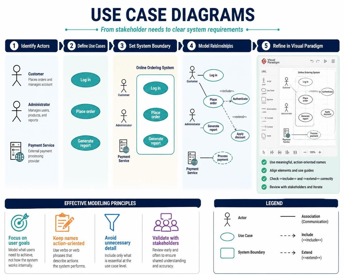
While the concept is straightforward, creating effective diagrams that are both comprehensive and easy to understand requires discipline and the right tools. Visual Paradigm stands out as a robust solution for modeling professionals, offering intuitive features that streamline the creation of UML diagrams. This guide will walk you through the principles of effective use case modeling, from identifying actors to defining complex relationships, and demonstrate how to leverage Visual Paradigm to bring your models to life.
Key Concepts in Use Case Modeling
1. The Core Components
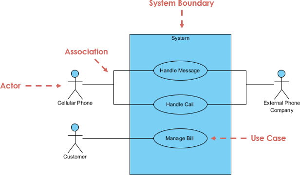
A use case diagram is built upon three primary elements:
-
Actors: These represent entities that interact with the system. An actor can be a human user (e.g., a Customer), another system (e.g., a Payment Gateway), or even hardware. Actors are typically depicted as stick figures.
-
Use Cases: These represent specific goals or functionalities that the system provides to the actors. Use cases are depicted as ovals and should describe what the system does, not how it does it.
-
Relationships: Lines connecting actors and use cases define the interactions. Additionally, relationships between use cases themselves help manage complexity and reuse behavior.
2. Identifying Effective Use Cases
The quality of your diagram depends heavily on the quality of the use cases you identify. Follow this process:
-
Identify Actors: List everyone and everything that will touch the system.
-
Determine Goals: For each actor, ask, “What do they want to accomplish?” Each distinct goal becomes a potential use case.
-
Define Scope: Ensure each use case delivers measurable value to the actor.
Characteristics of Good vs. Bad Use Cases
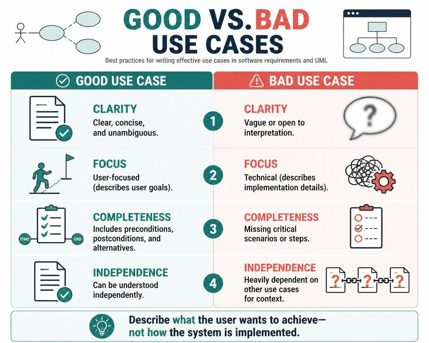
| Feature | Good Use Case | Bad Use Case |
|---|---|---|
| Clarity | Clear, concise, and unambiguous. | Vague or open to interpretation. |
| Focus | User-focused (describes user goals). | Technical (describes implementation details). |
| Completeness | Includes preconditions, postconditions, and alternatives. | Missing critical scenarios or steps. |
| Independence | Can be understood independently. | Heavily dependent on other use cases for context. |
3. Levels of Abstraction
To manage complexity, use cases are often categorized into three levels:
-
Summary Level (User Goals): High-level objectives that span multiple steps or sub-goals. Example: Manage Orders.
-
Primary Level (User Goals): Specific tasks that achieve a summary goal. Example: Order Food, Order Wine.
-
Subfunction Level (Sub-Goals): Detailed steps required to complete a primary use case. Example: Serve Food, Cook Food.
Starting with summary-level use cases helps stakeholders grasp the big picture before diving into granular details.
Relationships Between Use Cases and Actors
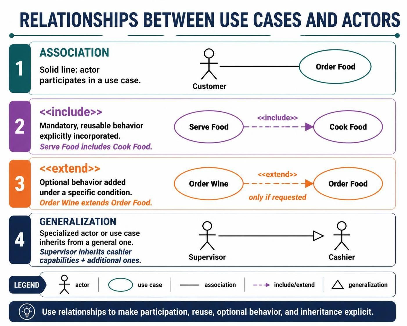
Understanding how elements connect is crucial for accurate modeling. Visual Paradigm supports all standard UML relationships:
-
Association: A solid line connecting an actor to a use case, indicating participation.
-
Include (
<<include>>): Indicates that one use case explicitly incorporates the behavior of another. This is used for mandatory, reusable functionality. Example: “Serve Food” includes “Cook Food.” -
Extend (
<<extend>>): Indicates that one use case adds optional behavior to another under specific conditions. Example: “Order Wine” extends “Order Food” only if the customer requests it. -
Generalization: Shows an inheritance relationship. One actor or use case is a specialized version of another. Example: “Supervisor” is a generalized form of “Cashier,” inheriting all cashier capabilities plus additional ones.
Practical Example: Restaurant Management System
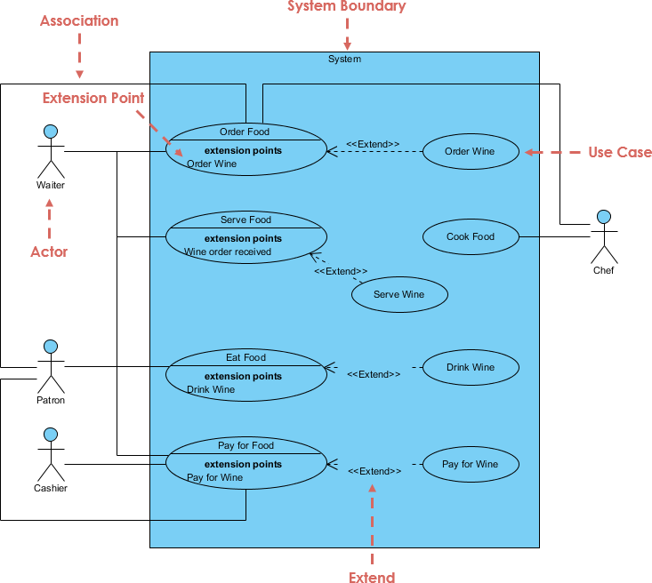
Let’s apply these concepts to a real-world scenario: a Restaurant Management System.
Actors
-
Waiter: Interacts with orders and service.
-
Chef: Responsible for food preparation.
-
Patron: The customer eating and drinking.
-
Cashier: Handles payments.
Use Cases by Actor
-
Waiter: Order Food, Order Wine, Serve Food, Serve Wine.
-
Chef: Cook Food.
-
Patron: Eat Food, Drink Wine.
-
Cashier: Pay for Food, Pay for Wine.
Relationships in Action
-
Association: The Waiter is associated with Order Food and Serve Food.
-
Include: The Serve Food use case includes Cook Food because the chef must prepare the meal before it can be served.
-
Extend: Order Wine extends Order Food as an optional addition to the main order.
-
Generalization: A Supervisor actor generalizes the Cashier actor, meaning the supervisor can perform all cashier duties plus administrative tasks.
Creating Use Case Diagrams with Visual Paradigm
Visual Paradigm simplifies the modeling process with a drag-and-drop interface and intelligent features. Here is how to create your first diagram:
-
Initialize Project: Open Visual Paradigm and start a new project. Select “Use Case Diagram” from the diagram types.
-
Add Actors: Drag the “Actor” shape from the toolbar onto the canvas. Label them clearly (e.g., Waiter, Chef).
-
Add Use Cases: Drag the “Use Case” oval shape onto the canvas. Name them according to the user goals identified earlier.
-
Define Relationships:
-
Use the “Association” tool to link actors to their respective use cases.
-
Use the “Include” and “Extend” connectors to show dependencies between use cases.
-
Use “Generalization” to show inheritance between actors or use cases.
-
-
Organize Layout: Use the built-in layout tools to arrange elements vertically or horizontally. This ensures the diagram is readable and professional.
-
Document Details: Double-click on any use case to add detailed descriptions, including preconditions, main success scenarios, and extensions.
-
Export and Share: Save your work and export the diagram as PNG, PDF, or other formats for inclusion in documentation or presentations.
Pro Tips for Visual Paradigm Users
-
Modeling Assistant: Enable the modeling assistant to receive real-time suggestions and validation checks as you build your diagram.
-
Templates: Start with pre-defined templates to save time and ensure consistency across projects.
-
Collaboration: Utilize Visual Paradigm’s cloud features to allow team members to view and comment on diagrams simultaneously, fostering better communication between developers and stakeholders.
Conclusion
Use case diagrams are more than just pictures; they are essential communication tools that bridge the gap between technical teams and business stakeholders. By focusing on user goals, maintaining clear levels of abstraction, and accurately defining relationships, you can create models that drive successful software development.
Visual Paradigm enhances this process by providing a powerful, user-friendly environment that supports best practices in UML modeling. Whether you are mapping out a simple application or a complex enterprise system, combining solid modeling principles with the right tooling ensures that your requirements are clear, complete, and ready for implementation.
Recommended Resources for Visual Paradigm Users
-
Introduction to UML Diagrams in Visual Paradigm: Overview of 14 UML diagram types available in Visual Paradigm and their unique purposes in modeling.
-
Online Use Case Diagram Tool: Features of Visual Paradigm Online’s drag-and-drop editor for creating professional use case diagrams in the cloud.
-
Free UML Tool: Details on the free UML modeling tool for non-commercial use, supporting 13 UML 2.x diagrams.
-
Free Use Case Diagram Tool: Information on the web-based editor for drawing use case diagrams without limitations on shapes or diagrams.
-
How to Draw Use Case Diagram?: Step-by-step instructions for modeling system functions and actors in Visual Paradigm.
-
Use Case Description in Visual Paradigm for UML: Guide to using VP-UML for building large-scale software systems through object-oriented approaches.
-
Use Case Diagram – UML 2 Diagrams: Explanation of creating use case diagrams to describe system behavior from an external viewpoint.
-
Online UML Diagram Tool: Features of Visual Paradigm Online’s UML tool, including syntax checks and a neat user interface.