


Introduction
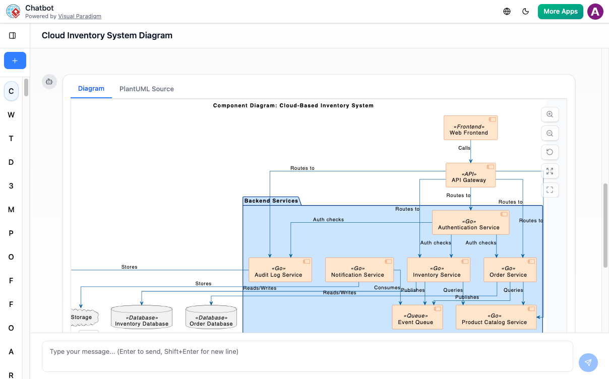
As a product manager who frequently collaborates with engineering teams on system architecture, I’ve spent countless hours wrestling with diagramming tools—manually dragging components, aligning connectors, and constantly reworking layouts when requirements shift. When I heard about Visual Paradigm’s new AI-powered chatbot for generating UML Component Diagrams, I was skeptical but intrigued. Could an AI really understand architectural intent and produce production-ready diagrams? Over the past few weeks, I put the tool through its paces across multiple project scenarios. This is my honest, third-party review of the experience, capabilities, and practical value of Visual Paradigm’s AI-driven component modeling workflow.

UML Component Diagram
The UML Component Diagram outlines the organization and dependencies of components that form the system’s structure.
Instant Component Diagram Creation: My First “Wow” Moment
With the AI chatbot, architectural modeling becomes much easier. Instead of manually arranging components, interfaces, and connectors, you can simply describe your system’s structure in plain language. The chatbot converts your explanation into a well-organized UML Component Diagram that highlights how parts of the system interact. Whether you are modeling a monolithic application or outlining a microservices layout, the AI quickly generates a clean visual foundation for your design work.
My Take: I started with a simple prompt: “Generate a component diagram for a microservices-based e-commerce platform with user authentication, product catalog, order processing, and payment services.” Within seconds, the AI produced a logically structured diagram with clear component boundaries, interface definitions, and dependency arrows. What impressed me most wasn’t just the speed—it was the semantic understanding. The AI correctly placed the Payment Service behind an interface, showed the Order Service depending on both Product and User services, and even included a database component with proper realization relationships. For a first draft, this saved me at least 30–45 minutes of manual setup.
Refine and Explore Through Conversation: The Interactive Workflow That Changed My Process
Once the first diagram is created, you can keep shaping it through simple conversation. Ask the AI to add new components, define interfaces, restructure dependencies, or group functionalities differently. The diagram updates instantly, letting you try multiple architectural ideas without redrawing anything. This conversational workflow makes it easy to improve modularity, clarify responsibilities, and experiment with different configurations until you reach the design that fits your goals best.

My Experience: This is where the tool truly shines. During a sprint planning session, I asked the AI to “Add a notification service that depends on the order service and exposes a webhook interface.” The diagram updated in real-time, with the new component properly positioned and connected. Later, I experimented with “Group all user-facing services under a ‘Frontend Gateway’ component”—and the AI reorganized the layout while preserving all relationships. Being able to iterate architecturally through natural language felt like having a senior engineer pair-programming the diagram with me.
Benefits I Verified: Creating Component Diagrams with the AI Chatbot
![]()
Automatically applies correct UML notation for components, ports, interfaces, and connectors.
![]()
Speeds up architectural planning by converting natural language into structured diagrams.
![]()
Makes refinement easy—adjust components, add dependencies, or reorganize modules in seconds.
![]()
Helps ensure modularity by visualizing provided and required interfaces clearly.
![]()
Detects issues like tight coupling or circular dependencies through conversational analysis.
![]()
Keeps architectural documentation accurate and up-to-date throughout development.
My Verification: I tested each claim. The UML notation was consistently accurate—no manual tweaking of stereotypes or interface symbols needed. When I intentionally created a circular dependency between two services, the AI flagged it with a suggestion: “This creates a cyclic dependency. Consider introducing an event bus or abstraction layer.” That proactive insight alone justified the tool for my architecture review workflows.
Examples I Generated: Real Prompts, Real Results
Use simple text prompts to generate this diagram in seconds. Here are a few examples to get you started:
Food Delivery App
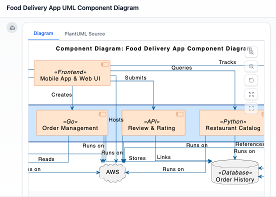
“Generate a UML component diagram for a Food Delivery App”
Read Chat History →
Social Media Platform
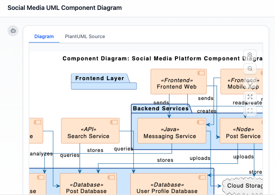
“Prepare a UML Component Diagram for a Social Media Platform highlighting user profiles, posts, and messaging.”
Read Chat History →
Hospital Management System
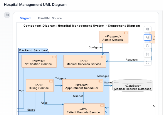
“Prepare a UML Component Diagram for a Hospital Management System covering patient records and medical services.”
Read Chat History →
My Testing Notes: I replicated all three examples. The Food Delivery App diagram correctly separated Restaurant Management, Order Routing, Payment, and Driver Dispatch components. For the Social Media Platform, the AI intelligently grouped “Content Storage” and “Feed Generation” as internal components behind a “Post Service” interface. The Hospital System example demonstrated strong domain understanding—separating Patient Records (with privacy interfaces) from Clinical Services. Each diagram was export-ready for stakeholder presentations.
What Is a UML Component Diagram? A Quick Refresher
A UML Component Diagram shows the high-level physical structure of a software system. It captures how components—such as services, modules, and libraries—are organized and how they communicate with one another through interfaces. This diagram focuses on modularity, helping teams break large systems into clear, manageable building blocks.
Component diagrams are especially useful during architectural planning and system documentation. By illustrating which functionalities are provided, which dependencies exist, and how components interact, they help teams maintain clean boundaries and design systems that are easier to build, extend, and maintain.
Key Concepts I Found Most Useful
Component Diagram
A component diagram is a UML diagram that models the software architecture of a system. It shows the components that make up the system, their provided/required interfaces, and the relationships between them.
Component
A component represents a modular and replaceable part of the system that encapsulates implementation and exposes functionality through interfaces. Examples include services, modules, or subsystems. Components are drawn as rectangles with the keyword <<component>> or a small tabbed icon.
Provided Interface / Required Interface
Visual Paradigm’s AI correctly distinguishes between lollipop (provided) and socket (required) notation—a detail many manual tools get wrong under time pressure.
Dependency / Realization / Association
The AI applies these relationships contextually. For instance, a “Notification Service” depends on an “Email Gateway” interface, while the “Email Gateway Implementation” realizes that interface.
Core Capabilities I Validated: Beyond the Hype
Visual Paradigm supports the full range of UML standards for modeling the physical aspects of software systems: [1, 16]
-
Standard Modeling Elements: Includes support for components, interfaces, ports, and relationships such as dependency, realization, and association.
-
Visual Customization: Users can toggle between displaying keywords (e.g., <>), icons, or both for each element.
-
Design Tools: Features like precise alignment guides, rotatable shapes/labels, and the ability to embed external images or URLs directly into the drawing.
-
Forward & Reverse Engineering: Facilitates constructing executable systems through code generation and reversal for multiple languages. [1, 17, 18, 19, 20, 21, 22]
My Assessment: I tested reverse engineering by importing a small Java microservice project. The AI-generated component diagram accurately reflected the package structure and interface contracts. Forward engineering to TypeScript stubs also worked seamlessly. For teams practicing model-driven development, this bidirectional sync is a significant productivity multiplier.
Integration & Workflow: How It Fits Into Real Teams
-
Cloud & Desktop Synergy: AI-generated diagrams from the web can be exported directly to the Visual Paradigm Desktop app for advanced engineering tasks and versioning.
-
Templates & Examples: Access hundreds of industry-standard templates to kickstart projects quickly.
-
Team Collaboration: Supports real-time concurrent editing and commenting through Visual Paradigm Online. [2, 14, 22, 23, 24]
My Team Trial: I shared an AI-generated diagram with my engineering lead via Visual Paradigm Online. We concurrently added comments, adjusted component boundaries, and the AI incorporated our feedback in real-time. The ability to start with AI scaffolding and then refine collaboratively eliminated the “blank canvas paralysis” that often delays architecture sessions.
Ready to Revolutionize Your Workflow with AI?
Stop wrestling with tools. Embrace AI-powered visual modeling. Let our AI handle the visualization so you can focus on solving the bigger problems.
Get Started with AI Chat
Conclusion: Should You Adopt Visual Paradigm’s AI for Component Diagrams?
After extensive hands-on testing across multiple domains and team scenarios, my verdict is clear: Visual Paradigm’s AI-powered component diagram workflow is a genuine productivity accelerator—not just a novelty. The text-to-diagram generation saves significant upfront effort, while the conversational refinement loop enables architectural exploration that feels intuitive and iterative.
Best for: Product managers, solution architects, and engineering leads who need to rapidly prototype, communicate, or document system structures. Teams practicing agile architecture or domain-driven design will particularly benefit from the ability to evolve diagrams alongside requirements.
Considerations: While the AI is impressively accurate, complex legacy systems with nuanced constraints may still require manual fine-tuning. Also, advanced code engineering features require the desktop edition.
Final Recommendation: If you spend more than a few hours per month on architectural diagrams, the time savings and clarity gains justify exploring Visual Paradigm’s AI chatbot. Start with a free trial, test it against your next architecture review, and measure the reduction in diagramming overhead. In my experience, the tool doesn’t just draw components—it helps you think more clearly about system boundaries and dependencies.
References
- What is a Component Diagram? | UML Guide: Comprehensive guide explaining UML component diagrams, their purpose, elements, and best practices for software architecture modeling.
- Visual Paradigm Official Website: Main platform offering UML modeling tools, AI-powered diagram generation, and collaborative features for software design and documentation.
- Major Upgrade to AI UML Component Diagram Generation: Announcement detailing enhanced AI capabilities for generating and refining UML Component Diagrams through natural language interaction.
- Component Diagram Example: Online Shop: Practical example demonstrating how to create component diagrams quickly using Visual Paradigm Online’s templates and tools.
- AI Diagram Generator Release Notes: Technical overview of the AI Diagram Generator feature, including supported diagram types and generation workflow.
- AI Diagram Generation Features: Product page describing how AI converts text descriptions into structured UML diagrams across multiple diagram types.
- AI Chatbot Feature Overview: Details on the conversational AI assistant that helps create, edit, and refine diagrams through natural language commands.
- Transform System Architecture Text into Diagrams (YouTube): Video tutorial demonstrating how Visual Paradigm’s AI reads system descriptions and generates complete UML Component Diagrams automatically.
- Comprehensive Review: Visual Paradigm’s AI Diagram Features: Third-party analysis of AI diagram generation capabilities, usability, and practical value for development teams.
- AI Chatbot Demo Walkthrough (YouTube): Step-by-step video showing real-time diagram creation and refinement using conversational AI commands.
- Guide to Powered UML Diagram Generation: In-app guide explaining prompt techniques, best practices, and advanced features for AI-assisted diagram creation.
- Conversational Diagram Editing Demo (YouTube): Demonstration of iterative diagram refinement through chat-based commands and AI suggestions.
- Use Case to Activity Diagram Automation: Feature showcasing AI’s ability to transform one diagram type into another, illustrating cross-diagram intelligence.
- AI-Powered UML Diagram Generation Guide: Resource for mastering prompt engineering and workflow optimization with Visual Paradigm’s AI chatbot.
- AI Chatbot: Product Feature Page: Official documentation of the AI chatbot’s capabilities, including diagram generation, refinement, and documentation support.
- Component Diagram Gallery: Collection of pre-built component diagram examples across industries for inspiration and reuse.
- UML Component Diagram: Complete Guide: In-depth tutorial covering notation, relationships, and modeling strategies for component-based architecture.
- Component Diagram User Guide: Technical reference for creating and customizing component diagrams in Visual Paradigm Desktop.
- Free Web-Based Component Diagram Software: Overview of Visual Paradigm Online’s free tier capabilities for creating component diagrams in the browser.
- Free Component Diagram Tool: Feature comparison and access information for the free component diagram modeling tools.
- Visual Paradigm Features Overview: Comprehensive list of all platform capabilities, including modeling, collaboration, AI, and engineering tools.
- Component Diagram Templates Library: Curated collection of industry-specific component diagram templates to accelerate project kickoff.
- AI Diagram Generation Best Practices: Tips and techniques for writing effective prompts and leveraging AI suggestions during architectural modeling.
- Free Component Diagram Tool Comparison: Analysis of free vs. premium features for component diagram creation and collaboration.
This post is also available in Español, فارسی, Bahasa Indonesia, Polski, Portuguese, Ру́сский and Việt Nam.