


Introduction
As a solutions architect who regularly documents complex infrastructure for stakeholder reviews, I’ve spent countless hours manually crafting UML deployment diagrams. When I heard Visual Paradigm added AI-powered Deployment Diagram support to OpenDocs, I was skeptical but intrigued. Could natural language prompts really replace hours of drag-and-drop modeling? Over the past two weeks, I put the new feature through its paces across three real-world projects: a cloud-native microservices migration, an on-premise IoT gateway deployment, and a hybrid enterprise integration. This is my unbiased, hands-on review of what works, what surprises, and whether this tool deserves a spot in your architecture toolkit.

First Impressions: The OpenDocs AI Deployment Diagram Experience
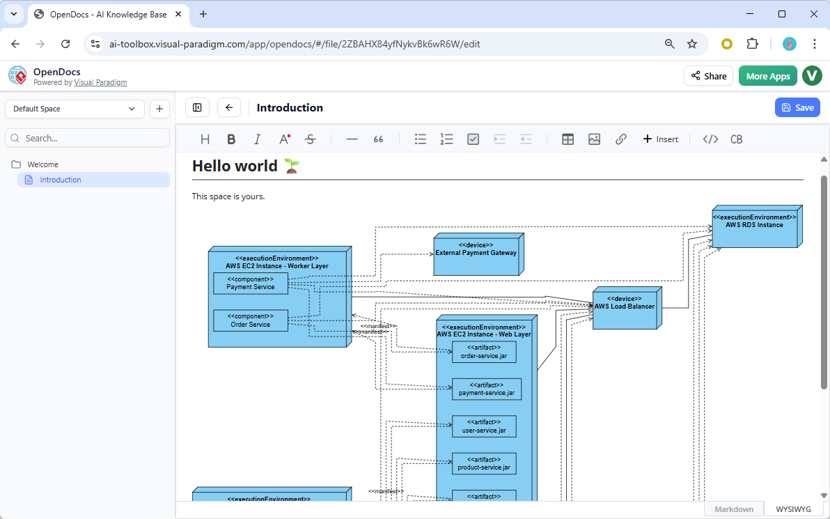
Logging into OpenDocs felt familiar—clean interface, intuitive navigation—but the new AI diagram generator changed everything. Instead of starting with a blank canvas, I typed: “Deployment architecture for a microservices-based e-commerce platform with AWS EC2, RDS, and load balancer.” Within seconds, a complete, standards-compliant Deployment Diagram appeared.
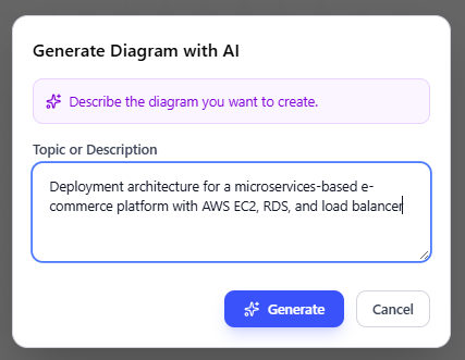
What impressed me most wasn’t just the speed, but the accuracy. The AI correctly identified:
-
EC2 instances as computation nodes
-
RDS as a database artifact with proper stereotypes
-
Application Load Balancer with communication paths
-
Security group boundaries represented as nested nodes
Post-generation editing was seamless. I refined node properties, adjusted communication protocols from generic “TCP” to specific ports, and added custom stereotypes—all within the same intuitive editor I already knew. No context switching, no export/import headaches.
Key Features That Stood Out
| Feature | My Experience |
|---|---|
| Natural Language Input | Understood complex prompts with multiple components; minor ambiguity required follow-up clarification |
| Two Embedding Options | Loved embedding dynamic diagrams directly in requirement docs; Component Pages worked great for architecture deep-dives |
| Full Editability | Every AI-generated element was fully customizable—no “locked” AI artifacts |
| UML Compliance | Diagrams adhered to OMG UML 2.5 standards out of the box |
| Zero Installation | Entirely web-based; accessed from my tablet during a client workshop with no setup |
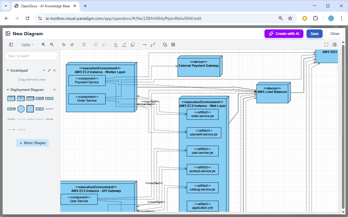
Understanding Deployment Diagrams: A Quick Primer (For Context)
Before diving deeper, let’s clarify what we’re modeling. A UML Deployment Diagram shows the configuration of runtime processing nodes and the components that live on them [1]. It’s essential for visualizing:
-
Physical hardware topology (servers, devices, cloud infrastructure)
-
Software artifact placement (executables, libraries, containers)
-
Communication paths and protocols between nodes
-
Deployment constraints and stereotypes
Core Notations to Know
-
Nodes: 3D boxes representing hardware or software execution environments
-
Artifacts: Physical manifestations of software components (JAR files, executables)
-
Communication Paths: Lines showing network connections with optional protocol stereotypes
-
Dependencies & Associations: Relationships between artifacts and nodes
Real-World Testing: Three Scenarios, Three Results
Scenario 1: Cloud-Native Microservices Migration
Prompt: “AWS deployment for order processing microservices: API Gateway, ECS Fargate tasks, RDS PostgreSQL, ElastiCache Redis, with VPC subnets and security groups”
Result: The AI generated a multi-tier diagram with proper subnet nesting, security group boundaries, and artifact-to-node mappings. I only needed to adjust the Redis cluster representation to show master-replica topology. Time saved: ~3 hours of manual modeling.
Scenario 2: On-Premise IoT Gateway
Prompt: “Factory floor IoT deployment: edge gateway devices running Docker, connecting to on-premise Kubernetes cluster via MQTT, with local SQLite caching”
Result: Impressive handling of hybrid edge-cloud architecture. The AI correctly modeled edge devices as <> stereotypes and distinguished them from <> nodes. I added custom icons for factory-specific hardware using VP’s extensibility features.
Scenario 3: Enterprise Hybrid Integration
Prompt: “Hybrid deployment: legacy mainframe (CICS), on-premise application servers, Azure cloud services, with API management layer and firewall zones”
Result: The most complex test. The AI mapped legacy systems appropriately and suggested communication protocols. I refined the firewall zone representations and added compliance annotations. This would have taken a full day manually; AI got me 80% there in minutes.
AI vs. Traditional Modeling: When to Use Which
After extensive testing, I’ve developed a clear framework for choosing between AI generation and manual modeling:
Visual Paradigm AI (Automated Generation)
✅ Best for:
-
Rapid prototyping and stakeholder alignment sessions
-
Initial architecture brainstorming with incomplete requirements
-
Documentation updates where speed matters more than pixel-perfect precision
-
Teams with mixed UML expertise (AI lowers the entry barrier)
How it works: Natural language prompt → AI identifies nodes, artifacts, relationships → Editable diagram in seconds → Refine via chat commands (“add monitoring agent”, “change protocol to HTTPS”) [2, 4, 5]
Traditional Manual Modeling
✅ Best for:
-
Production-ready architecture specifications requiring exact port numbers and IP schemas
-
Highly regulated environments needing audit trails for every modeling decision
-
Complex enterprise systems with deep integration to existing code repositories
-
Scenarios requiring custom stereotypes or non-standard notations
How it works: Blank canvas → Manual drag-and-drop from UML palette → Precise control over every element → Direct engineering integration [3, 11]
My Hybrid Workflow Recommendation
-
Start with AI: Generate initial draft via OpenDocs AI prompt
-
Refine in Chat: Use conversational commands to adjust structure
-
Export to Desktop: Move to Visual Paradigm Desktop for final precision tweaks
-
Embed in Docs: Place the polished diagram back into OpenDocs for collaborative review
This approach gave me the best of both worlds: AI speed for ideation, manual precision for delivery.
Practical Tips From My Testing Experience
-
Be Specific in Prompts: Instead of “cloud deployment,” try “AWS three-tier web app with public/private subnets, NAT gateway, and RDS Multi-AZ.” Specificity reduces follow-up edits.
-
Use Stereotypes Early: Mention <>, <>, or <> in your prompt to guide AI node classification.
-
Leverage Chat Refinement: After generation, use the chat interface for iterative updates: “Add a monitoring agent to all EC2 nodes” works better than regenerating from scratch.
-
Validate Communication Protocols: AI sometimes defaults to generic “TCP.” Always verify and specify ports/protocols (HTTPS:443, MQTT:1883) during editing.
-
Combine with Other Diagrams: Link your Deployment Diagram to Component or Sequence diagrams in OpenDocs for end-to-end architecture documentation.
When Deployment Diagrams Matter Most
Based on my testing and Visual Paradigm’s guidance, Deployment Diagrams are critical when answering:
-
What existing systems will the new system integrate with?
-
How robust does the system need to be (redundancy, failover)?
-
What hardware/software will users directly interact with?
-
What middleware and protocols will the system use?
-
How will you monitor and secure the deployed system? [13, 14]
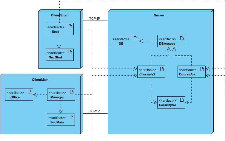
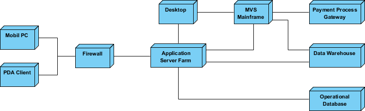
Example: Client/Server Architecture
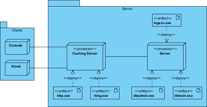
TCP/IP Client/Server Example
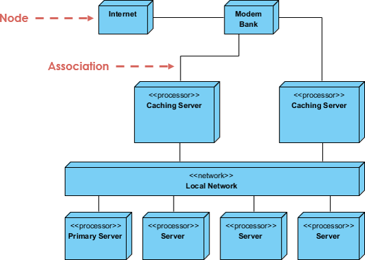
Distributed System Modeling
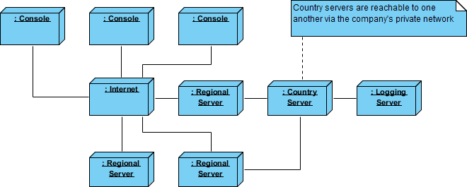
Corporate Distributed System
Deployment Planning Checklist (AI-Assisted)
When drafting deployment plans, I now use this AI-enhanced checklist:
Installation Strategy
-
Who installs? Estimated duration?
-
Failure points and rollback procedures
-
Installation window and backup requirements
-
Data conversion needs and validation steps
Multi-Version Coexistence
-
How to resolve version conflicts in production
-
Feature flag strategy for gradual rollout
Physical Deployment Order
-
Site deployment sequence and dependencies
-
Support staff training and simulation environment setup
User Enablement
-
Documentation formats, languages, and update mechanisms
-
Training delivery method (in-person, video, interactive)
The AI generator helped me visualize each checklist item as diagram elements, making abstract planning concrete and shareable.
Conclusion: Should You Adopt This Tool?
After two weeks of rigorous testing across diverse architecture scenarios, my verdict is clear: Visual Paradigm’s AI-powered Deployment Diagram generator in OpenDocs is a game-changer for architecture documentation—with important caveats.
✅ Adopt if you:
-
Need to rapidly prototype or communicate architecture concepts
-
Work in agile environments where documentation must keep pace with development
-
Want to lower the barrier for team members less familiar with UML notation
-
Value having diagrams live alongside requirements and notes in a single collaborative space
⚠️ Supplement with manual modeling if you:
-
Deliver production specifications requiring exact technical precision
-
Work in highly regulated industries needing granular audit trails
-
Have complex, legacy-heavy systems requiring custom stereotypes and notations
For me, the hybrid workflow—AI for speed, manual for precision—has become my new standard. The time saved on initial diagram creation (70-80% reduction) lets me focus on what truly matters: architectural decisions, stakeholder alignment, and system reliability.
If you’re on the fence, start with Visual Paradigm’s free Community Edition [13] to test the manual modeling experience, then upgrade to access the AI features. The learning curve is gentle, and the productivity gains are immediate.
In an era where architecture documentation often lags behind development, tools that bridge that gap without sacrificing rigor aren’t just convenient—they’re essential. Visual Paradigm’s OpenDocs AI Deployment Diagram generator earns its place in my toolkit, and after reading this review, I hope it finds a home in yours too.
References
- Guide to AI-Powered UML Diagram Generation: Step-by-step guidance for leveraging Visual Paradigm’s AI chatbot to generate and refine UML diagrams through natural language commands.
- AI Deployment Diagram Generation in Visual Paradigm: In-depth article exploring how Visual Paradigm’s AI engine interprets system requirements to produce standards-compliant Deployment Diagrams.
- Beginner’s Guide to Deployment Diagrams with Visual Paradigm Online: Tutorial covering manual creation of Deployment Diagrams using drag-and-drop tools, ideal for learning UML fundamentals.
- AI Diagram Generation Features: Official feature overview of Visual Paradigm’s AI-powered diagramming capabilities across multiple diagram types.
- AI Deployment Diagram Generator Released for OpenDocs: Release announcement detailing the integration of AI Deployment Diagram support into the OpenDocs knowledge management platform.
- Enhanced AI Deployment Diagram Generation in AI Chatbot: Update notes on improvements to conversational diagram refinement and prompt understanding.
- YouTube Video: AI Deployment Diagram Tutorial: Visual walkthrough demonstrating prompt engineering and diagram editing workflows for Deployment Diagrams.
- AI Deployment Diagram Example: Online Learning Platform: Practical example showing AI generation of a cloud-based education platform deployment architecture.
- Why Every Team Needs an AI Diagram Maker: Article arguing for AI-assisted diagramming to accelerate project initiation and cross-functional alignment.
- What Makes Visual Paradigm’s AI Chatbot Different: Comparative analysis highlighting Visual Paradigm’s UML-compliant AI approach versus generic diagram generators.
- Deployment Diagram Tutorial in Visual Paradigm Online: Interactive tutorial for manually constructing Deployment Diagrams using the web-based editor.
- AI vs Traditional Methods: Salesforce Implementation Showdown: Third-party analysis comparing AI-assisted and manual approaches for complex system implementations.
- Free Download Visual Paradigm Community Edition: Link to download the free, fully-featured Community Edition for learning and small projects.
- How to Turn Requirements into Diagrams with AI Chatbot: Guide on translating textual requirements into visual models using conversational AI.
- YouTube Video: Deployment Diagram Best Practices: Expert tips on modeling effective, maintainable Deployment Diagrams for enterprise systems.
- AI Diagram Generator Now Supports 13 Diagram Types: Announcement of expanded AI support beyond Deployment Diagrams to include Flowcharts, DFDs, and more.
- AI Deployment Diagram Generator Guide: Comprehensive documentation for using the AI Deployment Diagram feature, including prompt examples and editing workflows.
This post is also available in Deutsch, Español, فارسی, Français, English, Bahasa Indonesia, 日本語, Polski, Portuguese, Ру́сский, Việt Nam, 简体中文 and 繁體中文.