


Organizations constantly strive to streamline operations, reduce errors, and improve efficiency. However, without a shared language to describe how work actually flows, initiatives often stall in translation. This is where the Business Process Model and Notation comes into play. It is not merely a drawing tool, but a standardized method for visualizing the intricate dance of activities within an enterprise. Understanding this standard is crucial for anyone involved in operational design, system integration, or strategic planning.
For years, teams have relied on ad-hoc diagrams that look similar but mean different things to different stakeholders. One person sees a diamond as a decision point, while another sees it as a risk assessment. The standardization provided by BPMN resolves this ambiguity. It creates a common ground where business analysts, IT developers, and executives can converse without confusion. This guide explores the mechanics, the value, and the practical application of this notation without the noise of marketing hype.
Decoding the Standard: What Is It Really? 🧩
At its core, this notation is a graphical representation of a business process. It is a standard developed by the Object Management Group (OMG). The current widely adopted version is 2.0, which balances readability for business users with the precision required for technical implementation. Unlike proprietary formats that lock users into specific software ecosystems, this standard is open. It defines how to represent a process using specific shapes, colors, and connectors.
The philosophy behind the standard is simple: the diagram should be readable by humans and executable by machines. This dual nature is what sets it apart from generic flowcharts. While a flowchart might show that a decision was made, this notation specifies how that decision impacts the flow. It distinguishes between a manual task performed by a human and an automated task performed by software. This distinction is vital for modern automation strategies.
Key characteristics include:
- Standardization: Symbols mean the same thing everywhere, regardless of the author.
- Readability: Designed to be understood by business stakeholders, not just developers.
- Execution Readiness: The diagram can often be transformed into executable code or workflow logic.
- Extensibility: It allows for extensions to handle specific industry needs without breaking the core model.
The Building Blocks of the Notation 🔨
To read these diagrams effectively, one must understand the vocabulary. The notation is built upon a set of core elements. These elements are categorized by what they represent in the workflow. Understanding these categories allows you to deconstruct complex processes into manageable components.
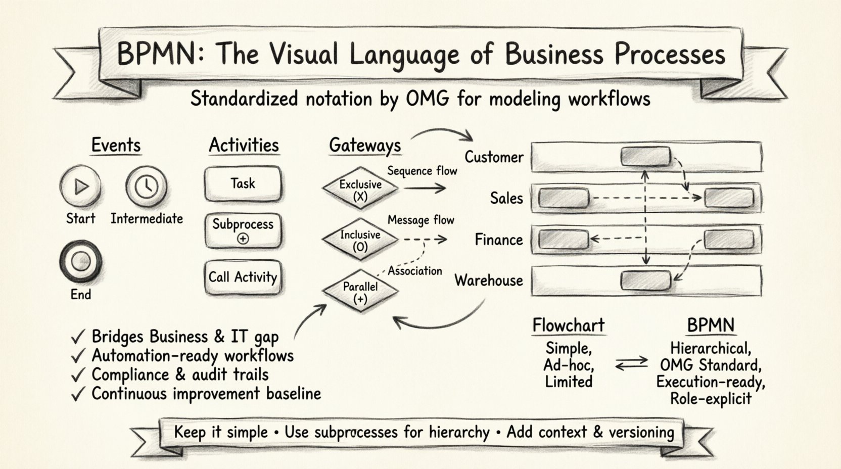
1. Events: The Triggers and Outcomes ⏱️
Events represent something that happens during the process. They are depicted as circles. The thickness of the circle border often indicates the type of event, though the internal icon is the primary identifier. Events generally fall into three buckets:
- Start Events: These trigger the process. They have a thin border and often contain a green play button or a clock icon.
- End Events: These signify the completion of the process. They are usually green with a thick border and a stop icon.
- Intermediate Events: These occur during the process. They have a single thin border and can represent waiting for a message, a timer, or a signal.
2. Activities: The Work Being Done 🛠️
Activities represent the actual work. They are drawn as rounded rectangles. This is where the process logic resides. There are several types:
- Tasks: The smallest unit of work. It could be a human clicking a button or a script running.
- Subprocesses: A complex task broken down into a smaller, self-contained process. This allows for abstraction, keeping the main diagram clean while providing detail in a separate view.
- Call Activities: References to a process defined elsewhere. This promotes reusability of logic.
3. Gateways: The Decision Points 🚦
Gateways control the divergence and convergence of paths. They are drawn as diamonds. They determine which path the process takes next based on logic. They do not add work themselves; they simply direct the flow.
- Exclusive Gateway: A decision where only one path is taken. Like a traffic light, it chooses one direction.
- Inclusive Gateway: A decision where one or multiple paths can be taken. It is more flexible than the exclusive type.
- Parallel Gateway: Used for splitting and merging flows. It ensures all paths are completed before moving on.
4. Connecting Objects: The Flow 🔄
These elements link the activities and events together. They show the sequence of the process.
- Sequence Flows: Solid lines showing the order of activities.
- Message Flows: Dashed lines showing communication between different participants or pools.
- Association Flows: Dotted lines linking artifacts or data to activities.
Structured Data: Common Symbols Explained 📋
To ensure clarity, the following table summarizes the most frequently used symbols and their meanings. This reference guide helps in interpreting diagrams quickly.
| Symbol Shape | Category | Meaning |
|---|---|---|
| Circle (Thin Border) | Event | Start of Process |
| Circle (Thick Border) | Event | End of Process |
| Rounded Rectangle | Activity | Task or Subprocess |
| Diamond | Gateway | Decision Point |
| Rectangle with Lines | Artifact | Text Annotation |
| Dashed Line | Connection | Message Flow |
| Solid Line | Connection | Sequence Flow |
Structuring Flow with Pools and Lanes 🏊
Complex processes often involve multiple departments, systems, or external partners. To visualize this, the standard uses a container concept called the Pool. A Pool represents a participant in the process, such as a company, a department, or an external vendor.
Inside a Pool, you will find Lanes. Lanes represent roles, teams, or systems within that participant. This structure allows you to see who is responsible for which task. It is essentially a matrix of responsibility and activity.
- Swimlanes: When multiple pools are not needed, lanes alone can divide work by role. For example, a lane for “Sales,” a lane for “Finance,” and a lane for “Warehouse” within a single order fulfillment pool.
- Collaboration: When two pools interact, message flows connect them. This visualizes handoffs between organizations. For instance, a “Customer” pool sends a message to an “Order Processing” pool.
This separation is critical for identifying bottlenecks. If a process stays in one lane for too long, that role is overwhelmed. If it crosses lanes frequently, communication overhead might be high. The visual layout makes these issues apparent immediately.
Why This Standard Matters for Business 🏢
Implementing this notation is not about creating pretty pictures. It is about operational clarity. There are tangible benefits to adopting this standard as the primary language for process design.
1. Bridging the Gap Between Business and IT 🤝
Historically, business analysts wrote requirements that developers struggled to interpret. Conversely, developers built systems that did not align with business needs. This standard provides a visual specification that both sides understand. A business analyst can draft a diagram, and a developer can see exactly what logic needs to be coded. This reduces the need for lengthy documentation and minimizes miscommunication.
2. Enabling Automation Readiness 🤖
As organizations move toward robotic process automation (RPA) and workflow engines, the distinction between human and machine tasks becomes paramount. This notation explicitly marks which tasks are manual and which are automated. When a process is modeled this way, it can be directly imported into execution engines. The diagram serves as the blueprint for the software that will run the process.
3. Compliance and Auditability ✅
In regulated industries, knowing exactly how a transaction occurs is a legal requirement. A standardized process diagram provides a clear audit trail. It documents the decision points, the approvals required, and the data flow. When an audit occurs, the diagram serves as the definitive source of truth for how the process is supposed to work.
4. Continuous Improvement 📈
You cannot improve what you cannot measure. Having a standardized model allows organizations to track performance against the design. If the actual execution deviates from the model, it signals a process failure or a need for redesign. It supports a culture of continuous improvement by providing a baseline for comparison.
Navigating Common Implementation Challenges ⚠️
While the standard is robust, applying it correctly requires discipline. Many teams struggle with specific pitfalls that reduce the value of the diagrams.
Overcomplicating the Model
A common mistake is trying to capture every single detail in one diagram. This leads to spaghetti diagrams that no one can read. The solution is hierarchy. Use subprocesses to hide complexity. Keep the top-level diagram focused on the major milestones. Only drill down into details when necessary.
Ignoring the Data Flow
Processes move data. However, many models focus solely on the activity flow. It is important to understand what data is required to start a task and what data is produced by it. While the notation allows for data objects, they are often overlooked. Ensuring data integrity is part of the process design.
Lack of Context
A diagram without context is just a map without a legend. Every diagram should have a title, a version number, and a description of the scope. Who is the audience? What is the goal? Without this metadata, the diagram loses meaning over time.
Bridging the Gap Between Design and Execution 🔄
The ultimate goal of modeling is to change how work gets done. This requires a transition from static diagrams to dynamic execution. The standard supports this transition through specific execution semantics.
- Human Task Management: The notation defines how human tasks appear in a worklist. It ensures that the right person sees the right task at the right time.
- Exception Handling: It provides mechanisms for handling errors. What happens if a message is not received? What happens if a gateway condition is not met? These are defined in the model.
- Versioning: Processes change. The standard supports versioning to ensure that old instances do not break when a new version of the process is deployed.
By treating the diagram as a living document, organizations can evolve their operations without losing track of the original intent. This flexibility is essential in a market that changes rapidly.
Comparing Approaches: BPMN vs. Flowcharts 📊
Many organizations ask why they need this standard when they already use flowcharts. While flowcharts are useful for simple logic, they lack the depth required for complex enterprise systems.
| Feature | Flowchart | This Standard |
|---|---|---|
| Complexity | Low | High (Hierarchical) |
| Automation Ready | No | Yes |
| Roles/Responsibility | Implicit | Explicit (Lanes) |
| Event Driven | Limited | Rich (Start, Intermediate, End) |
| Standardization | Ad-hoc | OMG Standard |
The table highlights that while flowcharts are quick to draw, they often fail to capture the nuances of enterprise architecture. This standard forces the modeler to think about events, roles, and exceptions, leading to more robust process designs.
Looking Ahead at Process Modeling 🚀
The landscape of process modeling is evolving. As digital transformation accelerates, the integration between modeling and execution becomes tighter. Future developments focus on increasing the level of abstraction allowed while maintaining execution precision.
There is also a growing emphasis on collaboration. Real-time collaboration on diagrams is becoming the norm. This allows teams to update the model as they discover new requirements, keeping the documentation fresh and accurate. The integration with data analytics is another frontier, allowing organizations to overlay actual performance data onto the model.
Ultimately, the standard is a tool for thinking. It forces clarity. In a world of complex systems, clarity is the most valuable asset. By mastering the visual language, organizations can navigate complexity with confidence. They can design processes that are resilient, efficient, and aligned with their strategic goals.
The journey does not end with the diagram. It ends with the outcome. When the process is designed well, the execution follows naturally. The standard provides the map, but the organization must provide the will to walk the path. With the right understanding of the symbols and the principles behind them, teams can transform chaos into order.
Whether you are designing a customer onboarding flow or a supply chain logistics network, the principles remain the same. Define the start, map the work, handle the decisions, and mark the end. Keep it simple, keep it standard, and keep it focused on value.
This post is also available in Deutsch, Español, فارسی, Français, English, Bahasa Indonesia, 日本語, Polski, Portuguese, Ру́сский, Việt Nam, 简体中文 and 繁體中文.