


Organizations often start their process mapping journey with simple boxes and arrows. These basic flowcharts serve a purpose, but they lack the semantic depth required for complex operational environments. When a business requires precision, automation readiness, and clear accountability across multiple departments, a more robust standard becomes necessary. This is where Business Process Model and Notation enters the picture.
BPMN is not merely a drawing standard; it is a universal language for business processes. It bridges the gap between business stakeholders and technical implementation teams. By adopting this notation, teams can ensure that a process model remains consistent regardless of who reads it. This guide explores the structural components, semantic rules, and governance strategies required to leverage BPMN effectively without relying on specific tooling.
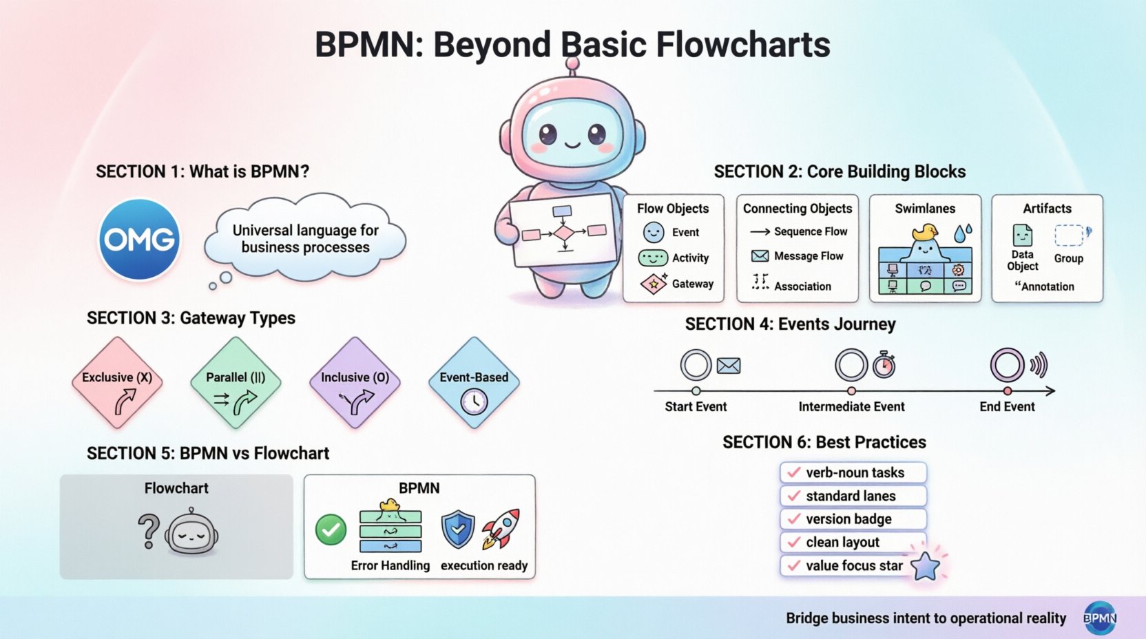
🔍 What Is Business Process Model and Notation?
BPMN is an open standard managed by the Object Management Group (OMG). It was designed to be understandable by all business stakeholders, from process owners to developers. Unlike proprietary diagramming methods, BPMN relies on a standardized set of symbols that carry specific meanings. This standardization reduces ambiguity. When a team member sees a specific symbol, the interpretation is consistent across the industry.
The standard has evolved over time, with BPMN 2.0 being the current widely adopted version. This version introduced a direct mapping to executable languages, meaning a diagram could theoretically drive automation logic. However, even without execution, the value lies in clarity and communication.
🎯 Why Move Beyond Basic Flowcharts?
Basic flowcharts are excellent for high-level logic, but they struggle with specific business requirements. The limitations include:
- Lack of Context: Standard flowcharts often ignore the actor performing the task.
- Ambiguous Transitions: Arrows do not always indicate whether information is being passed or a status is changing.
- No Error Handling: Simple diagrams rarely account for what happens when a process fails.
- Limited Scalability: As processes grow, basic charts become difficult to navigate and maintain.
BPMN addresses these gaps by introducing structured containers, specific event types, and distinct flow paths.
🧩 Core Building Blocks of BPMN
Understanding the syntax of BPMN is the first step toward proficiency. The notation divides its elements into four primary categories. Each category serves a distinct function in the diagram.
1. Flow Objects
These are the core elements that define the process behavior. They are the actors and actions within the story.
- Events: Things that happen during the process. They are represented by circles.
- Activities: Work that is performed. These are represented by rounded rectangles.
- Gateways: Decision points that control the flow. These are represented by diamonds.
2. Connecting Objects
These elements link the flow objects together to create a logical path.
- Sequence Flow: Shows the order of activities. It is a solid line with an arrowhead.
- Message Flow: Represents communication between different participants. It is a dashed line.
- Association: Links an artifact to a flow object. It is a thin dashed line.
3. Swimlanes
Swimlanes provide a visual partitioning of the diagram to assign responsibility.
- Pools: Represent a major participant in the process, such as an organization.
- Lanes: Subdivisions within a pool that represent specific roles or departments.
4. Artifacts
Artifacts add extra information to the diagram without affecting the flow logic.
- Data Objects: Show what information is used or produced.
- Groups: Visual grouping of elements without changing behavior.
- Annotations: Text descriptions for clarity.
🆚 BPMN vs. Traditional Flowcharts
Distinguishing between BPMN and traditional flowcharts is critical for teams transitioning to the standard. The following table highlights the structural and semantic differences.
| Feature | Traditional Flowchart | BPMN |
|---|---|---|
| Notation Standard | Varies by organization | OMG Standard (BPMN 2.0) |
| Responsibility | Often implied or missing | Explicit via Pools and Lanes |
| Communication | Internal logic only | Explicit Message Flows between parties |
| Error Handling | Rarely depicted | Supported via Error Events |
| Execution Ready | No | Yes (with proper modeling) |
| Complexity | Simple linear paths | Complex loops, parallel paths, and interrupts |
This comparison demonstrates that while flowcharts are useful for quick sketches, BPMN is designed for comprehensive process definition. The explicit handling of communication and responsibility makes it superior for multi-departmental workflows.
🏗️ Structural Elements: Pools and Lanes
One of the most powerful features of BPMN is the ability to visualize boundaries. A Pool represents a distinct participant. For example, a single process might involve a customer, a bank, and a merchant. Each could be a separate pool.
Within a pool, Lanes break down responsibilities. If a single pool represents a “Sales Department,” the lanes could be “Inbound Sales,” “Outbound Sales,” and “Billing.” This structure ensures that every task has a designated owner.
🔑 Key Rules for Lanes
- One Lane per Activity: Every task must reside in exactly one lane.
- Entry and Exit: A process flow can cross lane boundaries, but the sequence flow remains within the pool.
- Message Flow Crossing: When communication happens between pools, the message flow crosses the boundary.
This structure prevents the common issue of vague ownership. If a task is stuck in a process, the lane immediately identifies who is responsible for moving it forward.
🚦 Managing Flow with Gateways
Gateways are the decision points in a BPMN diagram. They determine which path the process takes next. Unlike a simple flowchart diamond, BPMN gateways have specific behaviors that must be modeled correctly.
1. Exclusive Gateway (X)
This gateway represents a choice. Only one path is taken. It is used for conditions where A or B must happen, but not both.
- Example: If order value is over $1000, require manager approval. Otherwise, approve automatically.
- Logic: One incoming path, multiple outgoing paths with conditions.
2. Parallel Gateway (|)
This gateway splits the flow into multiple paths that happen simultaneously. All paths must be completed before the next step can occur.
- Example: Send email notification and update the database at the same time.
- Logic: One incoming path, multiple outgoing paths. No conditions apply.
3. Inclusive Gateway (O)
This gateway allows for multiple paths to be taken, depending on conditions. It is a combination of exclusive and parallel logic.
- Example: Send SMS if mobile number exists AND send email if email address exists.
- Logic: Outgoing paths have conditions. One or more paths may activate.
4. Event-Based Gateway
This gateway waits for a specific event to occur before proceeding.
- Example: Wait for a payment confirmation or a timeout event.
- Logic: The process waits at the gateway until one event triggers a path.
Using the correct gateway type is essential for accuracy. Using a parallel gateway where an exclusive one is needed can lead to logical errors in execution or misunderstanding during review.
🔄 Events That Drive Process Logic
Events are the triggers and outcomes of a process. They are drawn as circles. The thickness of the circle border indicates the type of event.
Start Events
These mark the beginning of a process. They determine how the process is initiated.
- Message Start: Triggered by receiving a message (e.g., a form submission).
- Timer Start: Triggered at a specific time (e.g., monthly report generation).
- Signal Start: Triggered by a system-wide signal.
Intermediate Events
These occur in the middle of a process. They can pause the flow or add a step.
- Message Intermediate: Waiting for a reply from another system.
- Timer Intermediate: Waiting for a specific duration before proceeding.
- Error Intermediate: Handling an error caught during a task.
End Events
These mark the successful or unsuccessful conclusion of a process.
- Message End: Sends a message upon completion.
- Signal End: Triggers a signal for other processes.
- Terminate End: Stops the process immediately and does not allow for rollback.
Understanding the distinction between these events helps in designing robust workflows that handle interruptions and time delays effectively.
📝 Artifacts and Annotations
While flow objects drive the logic, artifacts provide the context. They do not change the execution path but are vital for human understanding.
- Data Objects: Show what data is required for a task. For example, a “Purchase Order” icon next to a “Review Order” task.
- Groups: Dotted rectangles that group related tasks visually. They do not enforce constraints.
- Annotations: Text boxes connected to elements to explain complex logic.
Overusing artifacts can clutter a diagram. The rule of thumb is to use them only when the diagram alone is insufficient to convey the necessary information.
🛡️ Governance and Standardization
Adopting BPMN requires more than just learning symbols. It requires governance to ensure consistency across the organization. Without standards, different teams will model the same process differently, leading to confusion.
📐 Naming Conventions
- Task Names: Use verb-noun format (e.g., “Review Invoice” not “Invoice Review”).
- Lane Names: Use standard department names (e.g., “Finance” not “The Money People”).
- Process Names: Include the scope and version (e.g., “Procure-to-Pay v1.2”).
🔄 Version Control
Processes change. A governance policy should define how versions are managed. Old versions should be archived, and new versions should clearly indicate changes. This ensures that audits can trace which process rules were active at any given time.
🎨 Visual Standards
- Direction: Define a standard reading direction (usually top-to-bottom, left-to-right).
- Layout: Keep the diagram clean. Avoid crossing lines where possible.
- Colors: Use color sparingly. If used, define what colors mean (e.g., red for errors).
🔗 Connecting Processes: Message Flows
A common mistake in modeling is confusing Sequence Flows with Message Flows. This distinction is crucial for understanding boundaries.
- Sequence Flow: Represents the flow of control within a single participant. It is a solid line.
- Message Flow: Represents the flow of information between two participants (Pools). It is a dashed line.
When a process in Pool A sends data to Pool B, a Message Flow is required. This indicates that the receiving pool must have a corresponding Start Event to receive that message. This explicit requirement prevents assumptions about data availability.
⚙️ Modeling for Execution vs. Documentation
Not all diagrams are intended for the same purpose. Teams should distinguish between models built for documentation and models built for execution.
Documentation Models
These focus on human understanding. They may omit technical details that are irrelevant to the business reader. The goal is clarity and high-level logic.
- Focus on major steps.
- Minimize technical gateways.
- Use natural language in annotations.
Execution Models
These are designed to be processed by software engines. They require strict adherence to syntax.
- All tasks must be assigned.
- All gateways must have exit paths.
- Data types must be defined for inputs and outputs.
Attempting to use an execution model for a high-level stakeholder presentation often results in confusion. Conversely, using a documentation model for automation leads to errors.
🚧 Common Modeling Pitfalls to Avoid
Even experienced modelers can fall into traps. Being aware of common issues helps maintain quality.
- Orphaned Gateways: A gateway with no outgoing path or no incoming path. Every element must connect logically.
- Impossible Loops: Creating a loop that cannot be exited. This causes infinite cycles.
- Mixed Responsibilities: Placing too many tasks in a single lane. A lane should represent a specific role, not a collection of unrelated tasks.
- Missing Error Paths: Failing to model what happens when a step fails. Every critical task should have an error handling path.
- Over-Modeling: Detailing every single click in a user interface. Focus on the business steps, not the UI clicks.
🚀 Future Directions in Process Modeling
The field of process modeling continues to evolve. As automation becomes more prevalent, the line between diagramming and coding is blurring. Current trends include:
- Integration with AI: Using artificial intelligence to suggest process improvements based on historical data.
- Real-time Monitoring: Linking models directly to operational data to show process health.
- Low-Code Adoption: Increasingly, diagrams are used as the primary interface for building applications without traditional coding.
Staying updated on these trends ensures that the modeling practice remains relevant. The core principles of BPMN, however, remain stable. The symbols and semantics provide a foundation that will not change rapidly.
📊 Summary of Best Practices
To conclude this overview, teams should adopt the following habits when working with BPMN:
- Keep it Simple: Start with the happy path before adding complexity.
- Validate Regularly: Walk through the model with stakeholders to verify accuracy.
- Standardize Symbols: Ensure everyone uses the same definitions for events and gateways.
- Document Assumptions: Use annotations to explain logic that is not obvious.
- Focus on Value: Model processes that deliver business value, not just internal bureaucracy.
By adhering to these standards, organizations can build a repository of process knowledge that is accurate, maintainable, and actionable. BPMN serves as the bridge between business intent and operational reality. Mastering this tool allows teams to navigate complexity with confidence and precision.
This post is also available in Deutsch, Español, فارسی, Français, English, Bahasa Indonesia, 日本語, Polski, Portuguese, Ру́сский, Việt Nam, 简体中文 and 繁體中文.