


In the complex landscape of organizational operations, clarity is the currency of efficiency. Yet, requirements often arrive as vague descriptions, conflicting stakeholder opinions, and scattered notes. This ambiguity creates a foundation of uncertainty that can lead to costly errors, system failures, and frustrated teams. To bridge the gap between abstract needs and concrete execution, organizations require a standardized language. Business Process Model and Notation (BPMN) provides this essential framework.
Understanding the Challenge of Ambiguity 🤔
Before diving into the mechanics of process mapping, it is crucial to acknowledge the problem being solved. Requirements gathering is notoriously difficult. Stakeholders often describe what they want in terms of outcomes rather than steps. For example, a manager might say, “We need to approve expenses quickly.” This statement lacks specific details:
- Who approves the expense?
- What is the threshold amount?
- What happens if the threshold is exceeded?
- How is the approval communicated?
- What occurs if the request is denied?
Without a visual and logical structure, these questions remain unanswered until implementation begins. When developers or operators attempt to build based on such inputs, they make assumptions. Assumptions are the root cause of rework. BPMN eliminates this risk by forcing the definition of every path, decision, and participant.
What is BPMN? 🏗️
Business Process Model and Notation is an open standard for modeling business processes. It is maintained by the Object Management Group (OMG). Unlike proprietary diagramming tools that invent their own symbols, BPMN uses a universal set of icons. This universality means that a diagram created by one team can be understood by another, regardless of the software used to create it.
The notation serves two primary audiences:
- Business Analysts: Who use it to document the current state of operations (As-Is).
- Technical Teams: Who use it to specify the logic for automation or software development (To-Be).
By adhering to the BPMN 2.0 specification, you ensure that the diagram is not just a pretty picture, but a precise definition of behavior.
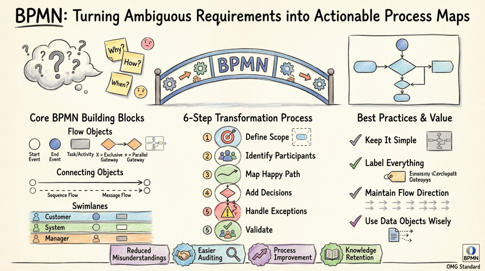
The Core Building Blocks of BPMN 🧩
A BPMN diagram is constructed from a few fundamental categories of elements. Understanding these components is the first step in transforming text into a map.
1. Flow Objects 🔄
These are the active parts of the diagram that drive the process forward.
- Events: Represent something that happens. They are depicted as circles. They have three types:
- Start Event: The trigger that initiates the process (e.g., “Receive Order”).
- Intermediate Event: Something that happens during the process (e.g., “Wait for Approval”).
- End Event: The conclusion of the process (e.g., “Order Shipped”).
- Activities: The work that needs to be performed. These are rounded rectangles. They can be:
- Tasks: The smallest unit of work.
- Sub-Processes: A collection of tasks that can be expanded into detail.
- Gateways: Points where the flow diverges or converges. These are diamonds.
- Exclusive Gateway (XOR): Only one path is taken (e.g., “Approved? Yes/No”).
- Parallel Gateway (AND): Multiple paths happen simultaneously (e.g., “Email Customer AND Update Inventory”).
- Inclusive Gateway (OR): One or more paths are taken based on conditions.
2. Connecting Objects 🔗
These elements link the flow objects together.
- Sequence Flow: Indicates the order of activities. Drawn as a solid line with an arrow.
- Message Flow: Shows communication between different participants or pools. Drawn as a dashed line with an open circle at the start.
- Association: Links text annotations or data objects to flow objects.
3. Swimlanes and Pools 🏊
Complex processes involve multiple roles. BPMN visualizes this using pools and lanes.
- Pools: Represent distinct participants, such as “Customer,” “Sales Team,” or “External Vendor.”
- Lanes: Sub-divisions within a pool that represent specific roles or departments (e.g., “Manager,” “Clerk,” “System”).
Using swimlanes clarifies responsibility. If a task is in the “System” lane, it implies automation. If it is in the “Manager” lane, it requires human intervention.
From Text to Diagram: The Transformation Process 📝➡️📊
Turning ambiguous requirements into a formal map requires a disciplined approach. Follow these steps to ensure accuracy.
Step 1: Define the Scope 🎯
Do not attempt to map the entire organization at once. Identify a specific process boundary.
- What is the trigger? (e.g., A customer submits a form).
- What is the desired outcome? (e.g., A contract is signed).
Step 2: Identify Participants 👥
List every entity involved. This helps determine the number of pools and lanes required.
Step 3: Map the Happy Path 🛣️
Start by drawing the ideal scenario where everything goes right. Ignore exceptions for now. This establishes the primary flow of value.
Step 4: Integrate Decision Points 🚦
Where does the process branch? Add gateways to represent business rules. Ensure every gateway has a labeled path for every possibility (e.g., Yes/No, Pass/Fail).
Step 5: Add Exceptions and Error Handling ⚠️
Real life is messy. Define what happens when things go wrong.
- What if the data is invalid?
- What if a system is unavailable?
- What if an approval is denied?
Use Intermediate Catch Events to handle interruptions like timeouts or errors.
Step 6: Validate with Stakeholders 👀
Show the map to the people who do the work. Ask them: “Does this look like what you actually do?” Their feedback is the only validation that matters.
Common BPMN Symbols Explained 📋
To ensure your maps are readable by anyone, adhere to the standard symbols. Below is a reference guide for the most critical elements.
| Symbol Type | Shape | Function | Example Usage |
|---|---|---|---|
| Start Event | Thin Circle | Initiates the process | Form Submission Received |
| End Event | Thick Circle | Terminates the process | Invoice Generated |
| Task | Rounded Rectangle | Single unit of work | Verify Credit Score |
| Exclusive Gateway | Diamond with X | One path only | Is Credit > 700? |
| Parallel Gateway | Diamond with + | All paths proceed | Send Email & Print PDF |
| Message Flow | Dashed Line | Communication between pools | Customer to Vendor |
Best Practices for Clear Mapping 🌟
A diagram is only useful if it is understandable. Adhere to these guidelines to maintain high quality.
Keep It Simple 🧹
Do not create a giant diagram that spans five screens. If a process is complex, use Sub-Processes to encapsulate detail. A map should show the high-level flow, with the ability to drill down into specifics.
Label Everything Clearly 🏷️
Never rely on a reader to guess what a line means.
- Label every sequence flow.
- Label every gateway condition (e.g., “Yes”, “No”).
- Ensure task names use action verbs (e.g., “Approve”, not “Approval”).
Maintain Flow Direction 📐
Readers typically scan from top to bottom and left to right. Avoid crossing lines. If a line must cross another, use an explicit bridge symbol to indicate they do not connect.
Use Data Objects Wisely 💾
Distinguish between the action and the data. Use dashed lines to associate data objects (like “Purchase Order”) with the tasks that create or consume them.
Pitfalls to Avoid 🚫
Even experienced modelers make mistakes. Be vigilant against these common errors.
- Missing End Events: Ensure every path leads to a conclusion. Orphaned lines indicate incomplete logic.
- Unreachable Tasks: Check that there is a path from the start event to every task. If a task cannot be reached, it is dead code.
- Confusing Gateways: Do not use a Parallel Gateway for decisions. Parallel implies “and”. Use Exclusive for “or”.
- Too Much Detail: Do not list every single field on a form in the task name. Keep the task name focused on the outcome.
The Value of Standardization 📈
Why invest time in learning this notation? The return on investment comes from communication efficiency.
- Reduced Misunderstandings: When a developer reads a BPMN diagram, they understand the logic requirements without guessing.
- Easier Auditing: Compliance officers can trace the flow of data to ensure regulations are met.
- Process Improvement: It is difficult to optimize a process you cannot see. Visual maps highlight bottlenecks and redundant steps.
- Knowledge Retention: When employees leave, the diagram remains as the institutional memory of how the business operates.
Conclusion: Building a Foundation for Success 🏛️
Transforming vague requirements into actionable maps is not just about drawing boxes and lines. It is about rigorous thinking. It forces you to ask the questions that stakeholders often forget to answer. By adopting BPMN, you create a shared language that bridges the gap between business intent and technical reality. This standardization reduces risk, clarifies responsibility, and ultimately delivers better outcomes for the organization.
Start small. Map one process. Validate it. Then expand. With practice, the notation becomes second nature, and the clarity it brings becomes an asset to your entire workflow.
This post is also available in Deutsch, Español, فارسی, Français, English, Bahasa Indonesia, 日本語, Polski, Portuguese, Ру́сский, Việt Nam, 简体中文 and 繁體中文.