
Introduction
In the complex landscape of software development, clarity is king. As systems grow in sophistication, the need for precise documentation and effective communication among developers, architects, and stakeholders becomes critical. While code defines the logic, diagrams define the flow. Among the various Unified Modeling Language (UML) tools available, the Sequence Diagram stands out as an indispensable asset for visualizing how objects interact over time.
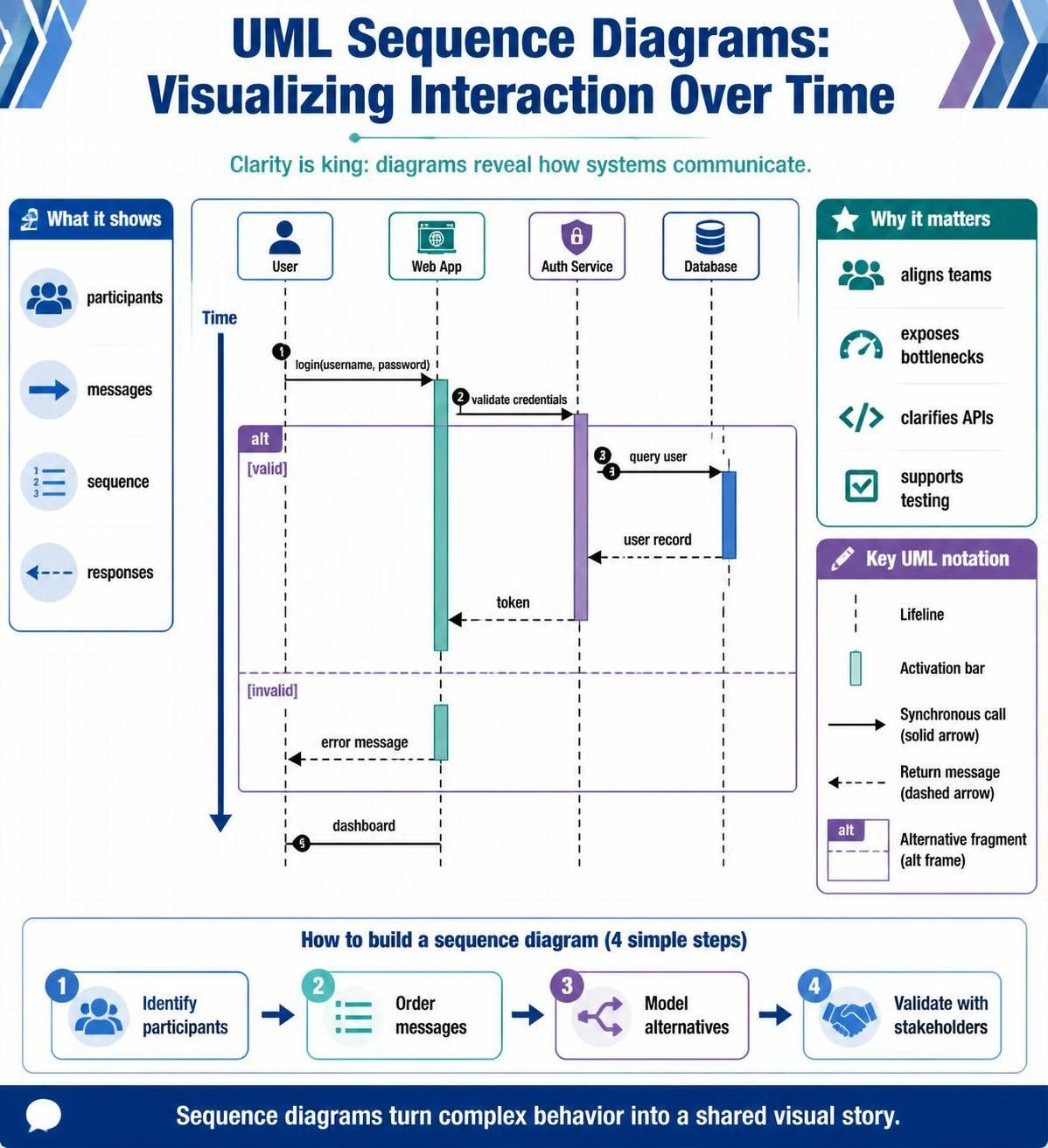
This guide provides a deep dive into sequence diagrams, exploring their core components, best practices for creation, and advanced features like combined fragments. Whether you are designing a new microservice architecture or documenting legacy code, mastering sequence diagrams will enhance your ability to communicate system behavior clearly and efficiently. We will also explore how to leverage Visual Paradigm, a powerful UML modeling tool, to create these diagrams with precision.
What is a Sequence Diagram?
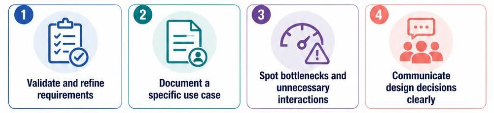
A sequence diagram is a type of interaction diagram that shows how objects operate with one another and in what order. It captures the interaction between objects in the context of a collaboration. Unlike class diagrams that show static structure, sequence diagrams illustrate dynamic behavior. They are particularly useful for:
-
Validating and fleshing out requirements.
-
Documenting the logic of a specific use case.
-
Identifying bottlenecks or unnecessary interactions in a system.
-
Communicating design decisions to technical and non-technical stakeholders.
Key Components of a Sequence Diagram
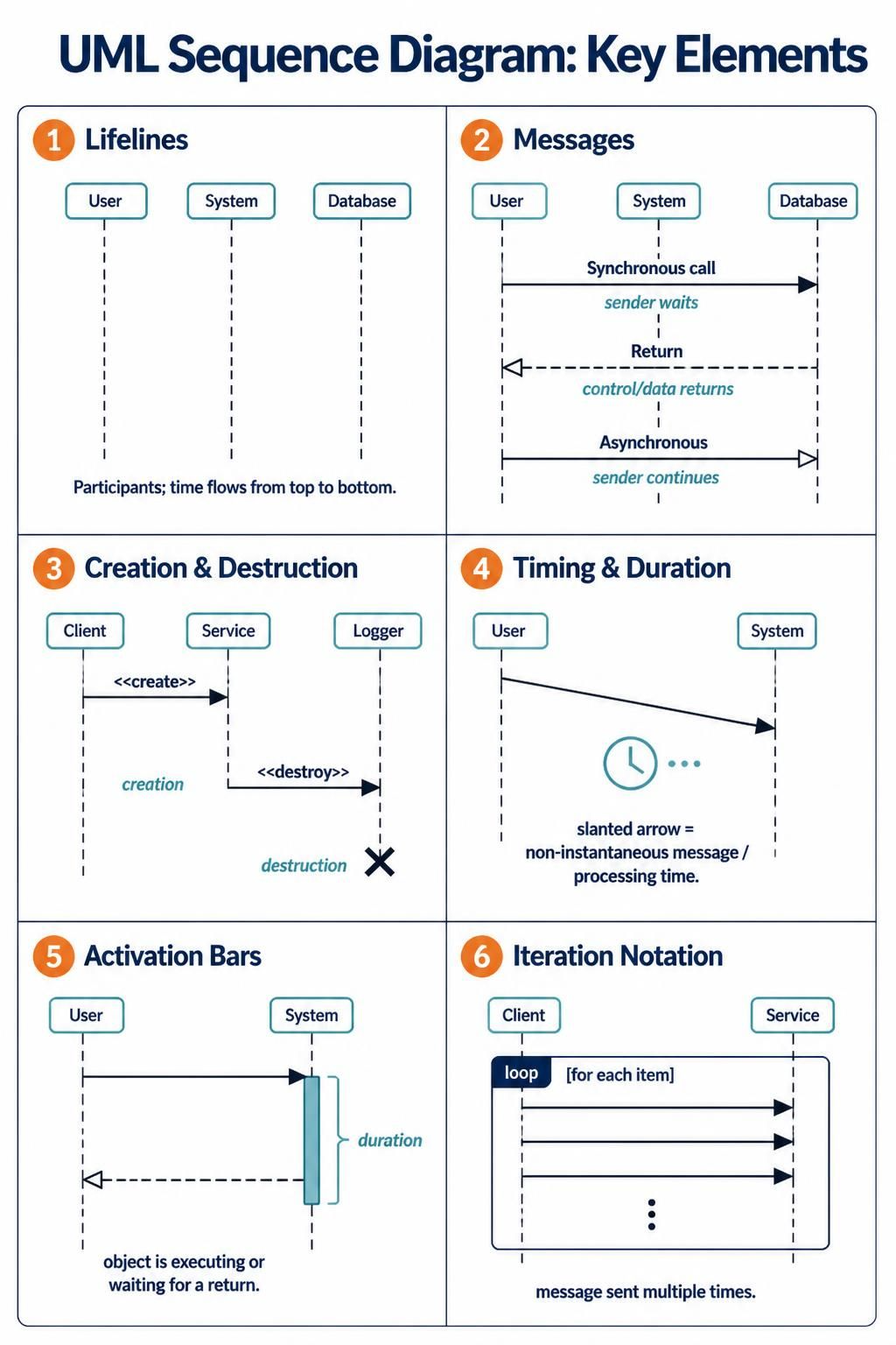
To read and create effective sequence diagrams, one must understand the standard UML notation. Below are the essential elements.
1. Lifelines
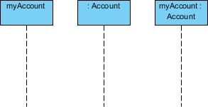
Lifelines represent the participants in the interaction. These can be objects, classes, actors, or components. Each lifeline is depicted as a vertical dashed line extending downward from a rectangular box containing the participant’s name. The vertical axis represents time, flowing from top to bottom.
2. Messages
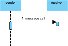
Messages are the heart of the sequence diagram, representing the communication between lifelines. They are shown as arrows connecting the lifelines. The style of the arrow conveys the type of message.
Synchronous Messages
These represent a call where the sender waits for the receiver to complete the task before continuing. They are depicted with a solid line and a filled arrowhead. This is typical for method calls or operation invocations.
Return Messages
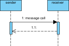
When a synchronous call completes, control returns to the sender. This is shown with a dashed line and an open arrowhead. It signifies the return of data or control flow.
Asynchronous Messages
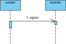
In asynchronous communication, the sender does not wait for a response. This is common in event-driven systems or multi-threaded applications. These are represented by a solid line with an open arrowhead.
3. Creation and Destruction Messages
Objects do not always exist for the entire duration of a scenario.
Constructor Messages: When an object is created during the interaction, a message arrow points to the newly created lifeline. The lifeline begins at the point of creation, lower down on the timeline than existing objects.
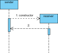
Destructor Messages: When an object is destroyed, its lifeline ends. This is often marked with an “X” at the end of the lifeline. Destructor messages are used when the destruction is triggered explicitly by another object’s action.

4. Timing and Duration
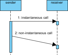
While many messages are considered instantaneous, some interactions involve significant processing time or network latency.
Non-Instantaneous Messages: To indicate a delay between sending and receiving, a slanted arrow is used. This visually communicates that time passes while the message is in transit or being processed.
5. Activation Bars
Also known as execution occurrences, activation bars are thin rectangles placed on top of the lifeline. They indicate the period during which an object is performing an action or waiting for a return. The length of the bar corresponds to the duration of the activity.
6. Iteration Notation
When a message is sent multiple times, such as iterating through a list, iteration notation is used. This is typically indicated by a loop frame or a label like *[for each item] near the message arrow.
Advanced Features: Combined Fragments
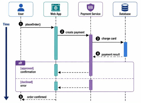
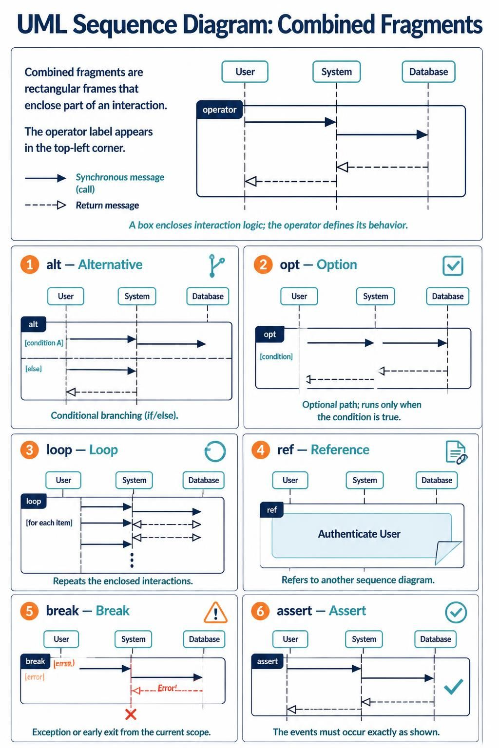
Real-world software logic rarely follows a single linear path. It involves conditions, loops, and optional steps. UML uses Combined Fragments to handle this complexity. A combined fragment is a box that encloses a portion of the interaction, with an operator in the top-left corner defining its behavior.
Common Fragment Operators
-
alt (Alternative): Represents conditional branching (if/else). Different sections within the fragment represent different paths based on conditions.
-
opt (Option): Represents an optional path. The interaction inside occurs only if a specific condition is true.
-
loop: Indicates that the enclosed interactions repeat. You can specify the minimum and maximum number of iterations.
-
ref (Reference): Refers to another sequence diagram. This is crucial for keeping diagrams manageable by breaking complex processes into smaller, referenced diagrams.
-
break: Represents an exception or early exit from the current scope, often used for error handling.
-
assert: Specifies that the sequence of events within the fragment must occur exactly as shown.
Step-by-Step Examples
Example 1: Simple Place Order Flow
Let’s visualize a basic e-commerce transaction involving three participants: Customer, Order, and Stock.
-
Initiation: The Customer creates a new Order object.
-
Item Addition: The Customer adds items to the Order.
-
Inventory Check: For each item, the Order checks availability with Stock.
-
Confirmation: If available, the item is added; otherwise, it is rejected.
-
Completion: The Order is saved, and the temporary interaction objects may be destroyed.

This diagram clearly shows the lifecycle of the Order object and its dependencies on the Stock system.
Example 2: Complex Order with Conditions
Now, let’s add complexity. Consider a scenario where delivery methods differ based on user status, and notifications are optional.
-
Member Status Check: The system checks if the member is VIP or Ordinary.
-
Conditional Delivery:
-
If VIP: Use Courier service.
-
If Ordinary: Use Standard Mail.
-
-
Optional Notification: If the user opted in, send a confirmation email.
This scenario utilizes alt fragments for the delivery method and an opt fragment for the notification.
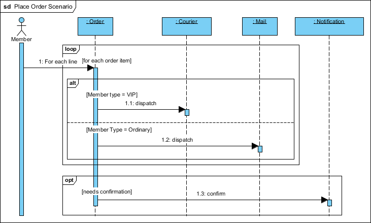
By using combined fragments, we avoid creating multiple separate diagrams for every possible variation, keeping the documentation concise yet comprehensive.
Best Practices for Creating Effective Sequence Diagrams
-
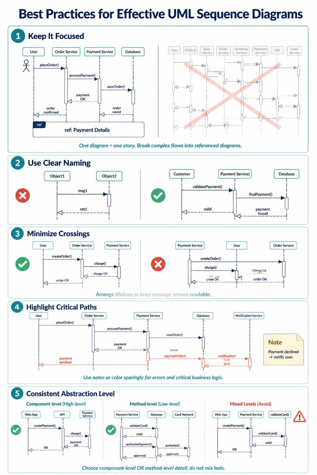
Keep It Focused: Each diagram should tell one story. Avoid cramming too many use cases into a single diagram. If it gets too complex, use
reffragments to break it down. -
Use Clear Naming: Lifelines and messages should have descriptive names. Instead of “msg1,” use “validatePayment().”
-
Minimize Crossings: Try to arrange lifelines so that message arrows do not cross unnecessarily. This improves readability.
-
Highlight Critical Paths: Use notes or colors to highlight error paths or critical business logic.
-
Consistent Abstraction Level: Decide whether you are modeling high-level component interactions or low-level method calls, and stick to that level within the same diagram.
Tooling: Visual Paradigm
Creating professional-grade sequence diagrams requires robust tooling. Visual Paradigm is a leading UML modeling software that offers comprehensive support for sequence diagrams and other UML artifacts.
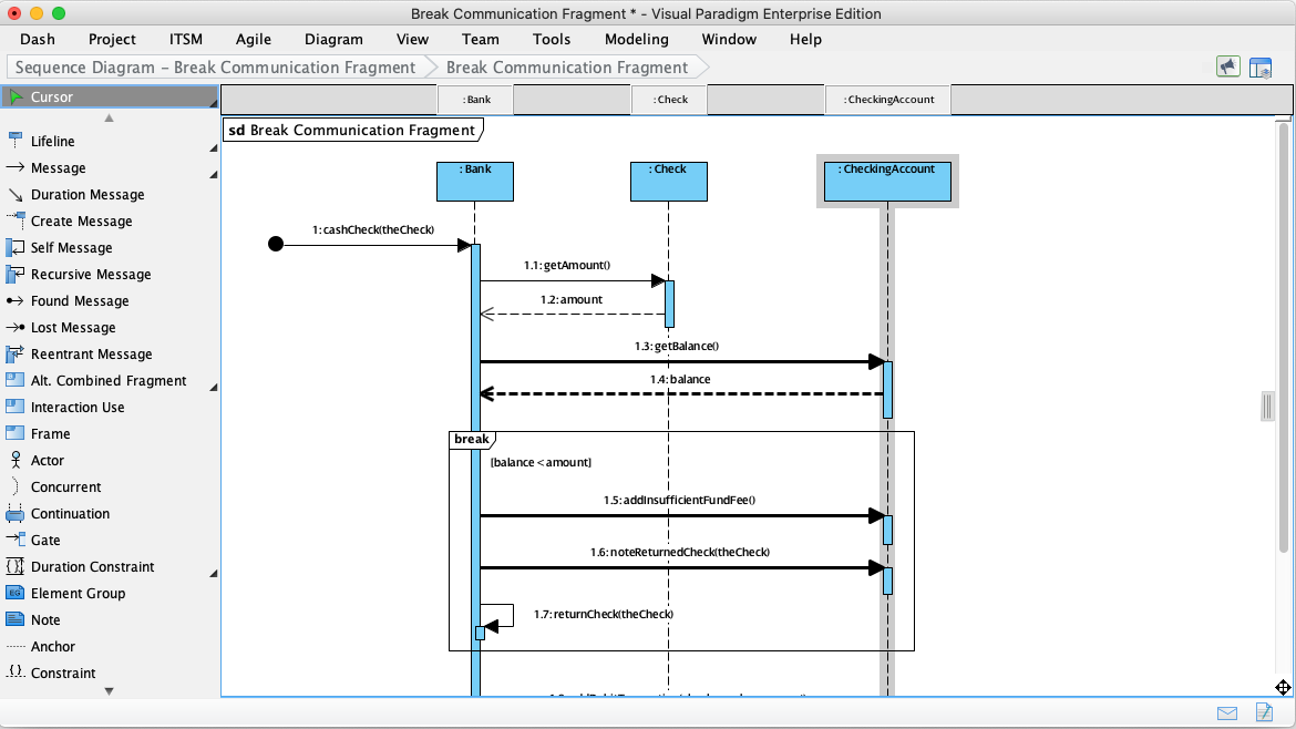
Why Visual Paradigm?
-
Intuitive Interface: Drag-and-drop functionality makes it easy to add lifelines, messages, and fragments.
-
Standard Compliance: Fully supports UML 2.x standards, ensuring your diagrams are universally understood.
-
Smart Connectors: Automatically adjusts message arrows and activation bars when you move lifelines, saving time on formatting.
-
Code Engineering: Visual Paradigm can generate code skeletons from sequence diagrams and reverse-engineer diagrams from existing code, bridging the gap between design and implementation.
-
Collaboration Features: Supports team collaboration with version control integration and real-time sharing options.
-
Free Community Edition: For individuals and small teams, Visual Paradigm offers a free community edition that includes essential UML modeling capabilities, making it accessible for learners and startups.
Using Visual Paradigm, you can quickly prototype interactions, validate logic with stakeholders, and generate documentation that stays in sync with your development process.
Conclusion
Sequence diagrams are more than just pretty pictures; they are vital communication tools that bridge the gap between abstract requirements and concrete implementation. By mastering the components—lifelines, messages, activation bars, and combined fragments—you can accurately model complex software behaviors.
Whether you are debugging a tricky race condition or designing a new feature, sequence diagrams provide the clarity needed to make informed decisions. Leveraging powerful tools like Visual Paradigm further streamlines this process, allowing you to focus on design logic rather than drawing mechanics. As software systems continue to evolve, the ability to visualize interactions remains a cornerstone of effective software engineering.
Recommended Resources on Visual Paradigm
- Mastering Sequence Diagram Modeling: A Practical Approach with Visual Paradigm: Provides a hands-on learning journey with examples for basic interaction, conditions, loops, exceptions, and parallel processes.
- 5.2 Interaction Modeling (Sequence Diagrams): Explains how to generate sequence diagrams directly from textual use case descriptions using AI, with practical examples like restaurant booking and ATM withdrawal.
- UML Sequence Diagrams: Behavior Blueprints: A guide on using sequence diagrams as behavior blueprints for distributed systems, covering key elements, real-world examples, and advanced techniques.
- Creating Sequence Diagrams in UML: A Comprehensive Tutorial: A complete tutorial covering sequence diagram notation, step-by-step drawing instructions, and examples like MVC architecture and hospital bed allocation.
- Practical 4: Behavioral Simulation: Focuses on behavioral simulation and modeling a “Borrow Book” use case using sequence diagrams, covering both AI generation and manual drawing.
- Tutorial: Diagramming a User Login Sequence: A step-by-step tutorial for creating a user login sequence diagram, covering conditional logic, return messages, and best practices for clarity.
- Conversational Sequence Diagrams: Introduces creating and refining sequence diagrams conversationally through Visual Paradigm’s AI Chatbot using natural language prompts.
- Mastering UML Interaction Diagrams: A Comprehensive Guide to Sequence and Communication Diagrams: A guide comparing sequence and communication diagrams, covering key concepts, notational differences, and practical examples with PlantUML.
- How to draw a Sequence Diagram in UML: A quick reference guide on the basic steps for creating sequence diagrams, including creating actors, lifelines, combined fragments, and managing operands.
- UML Sequence Fragments: Handling Alternatives and Loops: Explains how to use
alt,option,loop, andparfragments to model conditional logic, repetition, and parallelism in sequence diagrams.