
Introduction
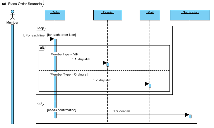
In software engineering, static diagrams often fail to capture the dynamic reality of business logic. Real-world systems rarely follow a single, linear path; they branch based on user roles, loop through data sets, and trigger optional events based on specific conditions. The “Place Order Scenario” diagram provided serves as a perfect case study for modeling this complexity.
This guide explores how to translate complex business rules—such as VIP versus Ordinary member handling—into clear, standardized UML Sequence Diagrams. We will focus specifically on leveraging Visual Paradigm, a leading modeling tool, to construct these interactions using Combined Fragments. By mastering loop, alt, and opt fragments, developers and analysts can create documentation that bridges the gap between abstract requirements and concrete implementation logic.
Key Concepts: Combined Fragments in UML
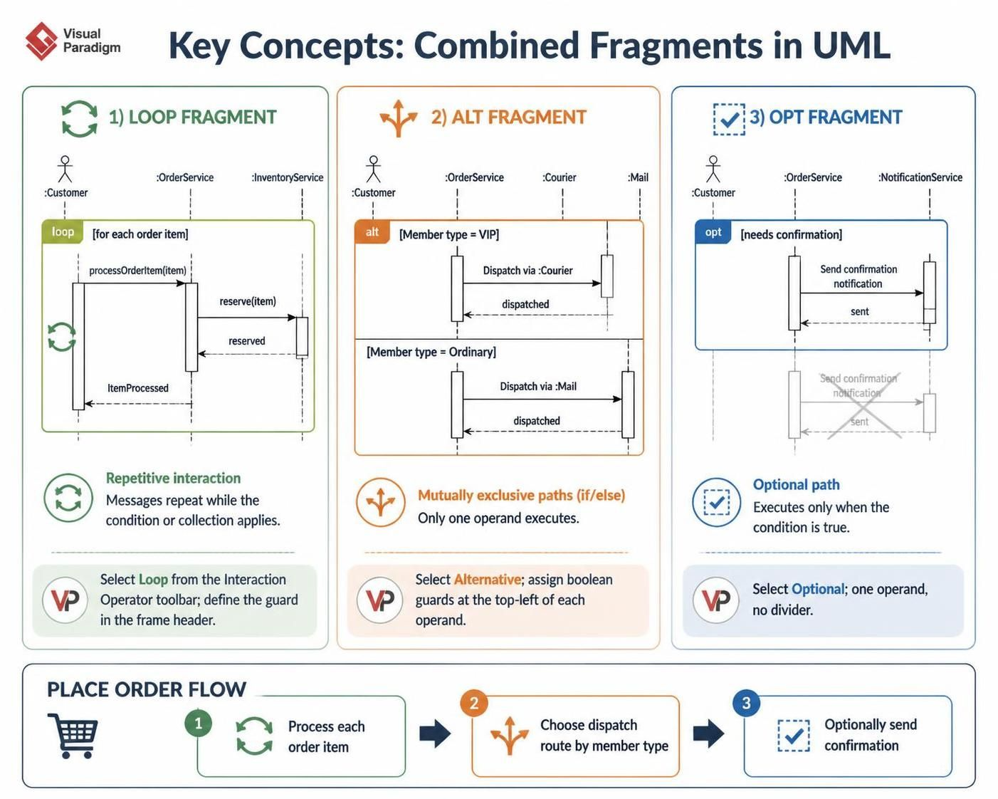
To accurately model the “Place Order” scenario, one must understand the three specific interaction operators used in the diagram. In Visual Paradigm, these are referred to as Combined Fragments.
1. The Loop Fragment (loop)
-
Definition: Represents a repetitive interaction. The messages inside this frame occur multiple times based on a specific condition or collection.
-
In Context: The order contains multiple line items. The system must process each item individually before moving to the next stage.
-
Visual Paradigm Tooling: When drawing a message, you can wrap it in a loop fragment by selecting the “Loop” operator from the Interaction Operator toolbar. You must define the guard condition (e.g.,
[for each order item]) in the header of the fragment.
2. The Alternative Fragment (alt)
-
Definition: Represents mutually exclusive paths (If/Else logic). Only one operand within the
altframe will execute based on the evaluation of guard conditions. -
In Context: The system checks the
Member Type.-
If VIP: Dispatch via
:Courier. -
If Ordinary: Dispatch via
:Mail.
-
-
Visual Paradigm Tooling: Use the “Alternative” operator. Visual Paradigm automatically creates the dividing line between operands. You assign the boolean condition (e.g.,
[Member type = VIP]) to the top-left corner of each operand section.
3. The Optional Fragment (opt)
-
Definition: Represents a path that only executes if a specific condition is true. If the condition is false, the interaction simply skips this section.
-
In Context: Not every order requires a confirmation notification. This step only happens if
[needs confirmation]evaluates to true. -
Visual Paradigm Tooling: Select the “Optional” operator. Unlike
alt, there is no dividing line; there is only one operand area containing the conditional logic.
Step-by-Step Implementation in Visual Paradigm
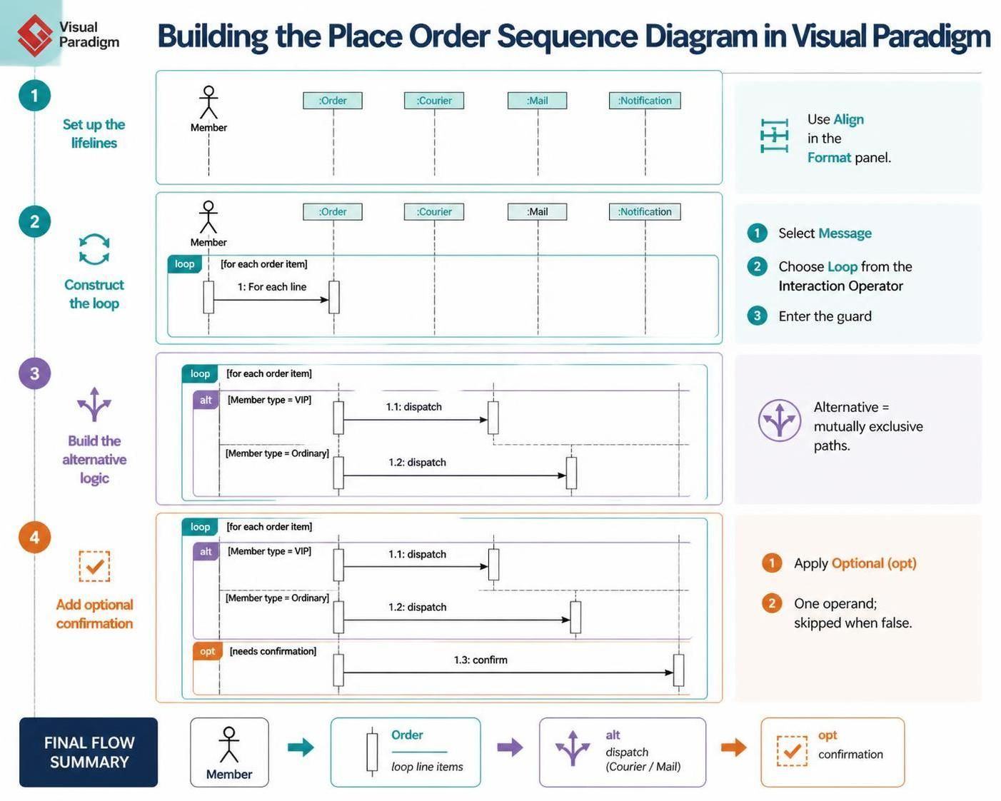
Below is a practical workflow for recreating the “Place Order Scenario” using Visual Paradigm’s interface.
Phase 1: Setting up the Lifelines
-
Open Visual Paradigm and create a new Sequence Diagram.
-
From the Diagram Toolbar, drag and drop an Actor icon and label it
Member. -
Drag and drop four Lifeline icons. Label them
:Order,:Courier,:Mail, and:Notification. -
Tip: Use the “Align” tool in the Format panel to ensure all lifelines are evenly spaced.
Phase 2: Constructing the Loop
-
Select the Message tool and draw a synchronous message from
Memberto:Order. Label it1: For each line. -
With the message selected, look for the Interaction Operator resource (often found in the smart manipulation menu or the main toolbar). Select Loop.
-
A frame will appear around the message. Click the header of the frame and type the guard:
[for each order item].
Phase 3: Building the Alternative Logic (VIP vs. Ordinary)
-
Inside the Loop frame, draw a message from
:Orderto:Courier. Label it1.1: dispatch. -
Select this message and apply the Alternative (alt) operator.
-
Visual Paradigm will split the frame.
-
Top Operand: Set the guard to
[Member type = VIP]. -
Bottom Operand: Draw a new message from
:Orderto:Mail. Label it1.2: dispatch. Set the guard to[Member Type = Ordinary].
-
-
Note: Ensure the activation bars (the thin rectangles on the lifelines) extend correctly during the dispatch phase to show processing time.
Phase 4: Adding the Optional Confirmation
-
Below the
altframe (but still logically associated with the order processing), draw a message from:Orderto:Notification. Label it1.3: confirm. -
Apply the Optional (opt) operator to this message.
-
Set the guard condition to
[needs confirmation].
Examples of Business Logic Application
Problem scenario:
- Trigger & Iteration: A system Member places an order containing one or more order items. For every individual line item in the order, a processing request is sent to the
: Ordercomponent. - Conditional Dispatching: Depending on the membership tier of the user placing the order, the fulfillment path branches:
- If the Member type is VIP, the
: Ordercomponent dispatches the item via the: Courierservice. - If the Member type is Ordinary, the
: Ordercomponent dispatches the item via the: Mailservice instead. - Optional Notification: Under the condition that the order needs confirmation, the
: Ordercomponent triggers a confirmation message to the: Notificationservice.
| Domain | Loop Condition | Alt Condition (Branch A / Branch B) | Opt Condition |
|---|---|---|---|
| E-Commerce Payment | For each payment method added | If Balance > Total (Wallet) / Else (Credit Card) |
If Transaction > $500 (Send Fraud Alert) |
| HR Onboarding | For each required document | If Role = Executive (Background Check) / Else (Standard Check) |
If Remote Worker (Ship Laptop) |
| Library System | For each book scanned | If Member = Student (Discount Rate) / Else (Full Rate) |
If Overdue (Calculate Fine) |
Conclusion
The “Place Order Scenario” demonstrates that effective UML modeling is about more than just connecting boxes; it is about capturing the decision-making intelligence of a system. By utilizing Visual Paradigm’s support for loop, alt, and opt combined fragments, you can transform vague requirements into precise technical specifications.
When documenting complex workflows, always remember:
-
Be Explicit with Guards: Never leave a condition implied. Always write
[Condition]clearly in the fragment headers. -
Nesting Matters: Notice how the
altandoptfragments sit inside or adjacent to theloop. This hierarchy tells the developer exactly when the logic applies. -
Keep it Readable: If a diagram becomes too crowded with nested fragments, consider breaking it down into separate diagrams or using “Interaction Uses” to reference sub-processes.
By following this guide, you can ensure your sequence diagrams serve as accurate blueprints for development, reducing ambiguity and preventing logic errors before a single line of code is written.