
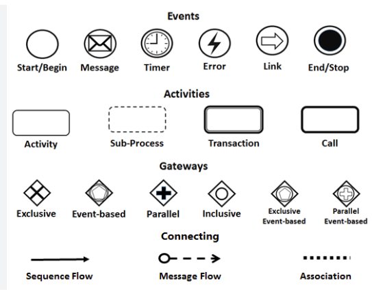
Business Process Model and Notation (BPMN) is the global standard for visualizing business processes. Unlike general flowcharts, BPMN provides a precise vocabulary that bridges the gap between business stakeholders and technical developers. By mastering these symbols, you can create diagrams that are not only readable but also executable by business process management (BPM) engines.
This guide breaks down the core components of BPMN 2.0, focusing on how to construct logical flows using Events, Activities, and Gateways.
1. The Pulse of the Process: Events
Events are the things that happen during a process. They are depicted as circles and act as triggers or outcomes. They do not consume time themselves but define the boundaries and context of the process steps.
- Start/Begin (Thin Circle): Marks the initiation point of a process. A process can have multiple start events, but only one will trigger the flow in a specific instance.
- End/Stop (Thick Circle): Represents the termination of a process. It indicates that the process has completed successfully or been terminated.
- Timer: Indicates that an event is triggered by time (e.g., “Every Monday at 9 AM” or “After 3 days”).
- Message: Signifies communication with an external entity. This is crucial for showing how different systems or departments interact.
- Error: Represents a specific error that interrupts the flow, requiring a distinct handling path.
- Link: A connector used to link parts of a large diagram together without drawing a continuous line across the page.
2. The Core Actions: Activities
Activities represent the work performed within the process. They are the “meat” of the diagram and are depicted as rounded rectangles.
- Task (Simple Activity): The most basic unit of work. This is an action that cannot or should not be broken down further (e.g., “Approve Invoice”).
- Sub-Process: A collection of activities grouped together to simplify a complex diagram. It can be expanded into its own detailed diagram for clarity.
- Transaction: A special sub-process where the entire sequence must succeed or fail as a single atomic unit. If any part fails, the whole transaction is rolled back.
- Call Activity: A reference to a reusable process definition defined elsewhere. This is excellent for modularizing common processes like “Customer Onboarding” that appear in multiple workflows.
3. The Decision Makers: Gateways
Gateways control the divergence and convergence of the flow. They act as traffic lights, deciding which path the process takes next based on conditions or parallel requirements.
- Exclusive Gateway (Diamond with X): Also known as a “Split Gateway.” The process chooses exactly one outgoing path based on a condition (e.g., If amount > $1000, go to Manager; else, go to Clerk).
- Parallel Gateway (Diamond with +): The process splits into multiple paths that happen simultaneously (e.g., Send Email AND Print Report).
- Inclusive Gateway (Diamond with O): Similar to Exclusive, but multiple paths can be taken if their conditions are met.
- Event-Based Gateway: The process waits for one of several events to occur (e.g., Wait for a Payment OR Wait for a Cancellation). This introduces a time-dependent element to the decision logic.
4. Connecting the Logic
To make the diagram functional, you must define the relationships between these shapes.
- Sequence Flow (Solid Arrow): Shows the order in which activities are performed. It flows from a Start Event, through Tasks and Gateways, to an End Event.
- Message Flow (Dashed Line with Circle/Dot): Represents communication between two separate “Pools” (parties). It shows information passing between entities, not the internal flow of a single process.
- Association (Dotted Line): Links an artifact (like a text note or group) to a specific element without affecting the process logic.
5. Putting It All Together: A Logic Example
When modeling a real-world scenario, you often combine these elements to handle complex logic. Below is a conceptual representation of how these symbols translate into a structured process flow.
[Start Event]
      |
      v
[Activity: Receive Order]
      |
      v
[Exclusive Gateway: Is Order Valid?]
   /        \
(Yes)      (No)
  |           |
  v           v
[Activity: Ship]  [Activity: Notify Customer]
  |           |
  +-----+-----+
        |
        v
[End Event]
By strictly adhering to these visual standards, you ensure that your diagrams are universally understood by analysts, developers, and business leaders alike. Remember: clear notation leads to clear execution.