
Introduction
In the world of software engineering and system design, understanding how different components interact over time is crucial. While static diagrams like class diagrams show structure, Sequence Diagrams reveal behavior. They model the collaboration of objects based on a time sequence, showing exactly how objects interact with others in a particular scenario of a use case.
This guide explores the power of Sequence Diagrams using Visual Paradigm, a tool that offers advanced visual modeling capabilities. With Visual Paradigm, you can create complex sequence diagrams in just a few clicks and even generate them automatically from the flow of events defined in your use case descriptions. Whether you are documenting an existing system or designing a new one, mastering these diagrams will enhance your ability to communicate technical processes clearly.
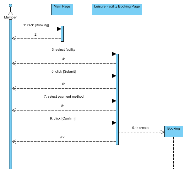
Key Concepts of Sequence Diagrams
A Sequence Diagram is composed of several key elements that work together to tell the story of an interaction. Below are the primary notations and concepts you need to know.
1. The Participants: Actors and Lifelines
Every interaction starts with participants. In UML, these are represented by Actors and Lifelines.
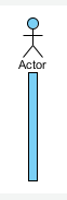
Actor
An Actor models a type of role played by an entity that interacts with the subject but is external to it. This could be a human user, external hardware, or another system.
-
Definition: An actor does not necessarily represent a specific physical entity but merely a particular facet (i.e., “role”) relevant to the specification of its associated use cases.
-
Properties: Name, Documentation, Abstract (if it cannot be instantiated), Leaf (if it cannot be specialized), and Operations.

Lifeline
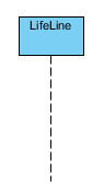
A lifeline represents an individual participant in the Interaction. It is the vertical dashed line that shows the existence of an object over time.
-
Types of Lifelines:
-
Standard Lifeline: Represents a generic object instance.
-
<>: Represents an interface between the system and its environment (e.g., a UI screen).
-
<>: Represents coordinating logic or workflow control.
-
<>: Represents persistent data or business objects.
-
-
Properties: Base Classifier, Multiplicity, Active (if it executes behavior upon creation), and Stopped (if it has received a destruction event).



2. Communication: Messages
Messages are the arrows that connect lifelines, representing communication and the flow of control.
-
Call Message: Represents an invocation of an operation on the target lifeline.

-
Return Message: Represents the pass of information back to the caller of a former message.

-
Create Message: Represents the instantiation of a new lifeline.

-
Destroy Message: Represents the request to destroy the lifecycle of the target lifeline.

-
Self Message: Represents an invocation of a message within the same lifeline (often used for internal processing).

-
Recursive Message: A specific type of self-message where the target points to an activation on top of the current activation.

-
Found Message: A message where the receiving event is known, but the sending event is outside the scope of the diagram (e.g., external noise or input).

-
Lost Message: A message where the sending event is known, but there is no receiving event (the message never reached its destination).

3. Controlling Flow: Combined Fragments
To model complex logic like loops and conditions, we use Combined Fragments.
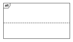
Alternative Combined Fragment (alt)
Represents a choice of behavior. At most one of the operands will be chosen, similar to an if-else statement in code.
-
Properties: Operator Kind, Interaction Operands, Covered LifeLines.

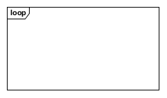
Loop Combined Fragment (loop)
Represents a loop where the operand is repeated a number of times.
-
Properties: Operator Kind, Interaction Operands.

Continuation
A syntactic way to define continuations of different branches of an Alternative Combined Fragment. It acts like a label in a flow of control.

4. Advanced Elements
Frame
The frame represents the interaction itself. It usually contains the label “sd” (for sequence diagram) and the name of the interaction.

Interaction Use
Allows you to reference another interaction. It’s a shorthand for copying the contents of a referred interaction, useful for keeping diagrams clean and modular.

Gate
A connection point for relating a message outside an Interaction Fragment with a message inside it.

Constraints and Notes
-
Constraint: A condition or restriction expressed in natural language or machine-readable format.

-
Time Constraint: Refers to a TimeInterval.

-
Duration Constraint: Refers to a DurationInterval.

-
Note: A comment attached to elements to provide remarks without semantic force.

Other Message Types
-
Concurrent: Represents concurrent method invocation along an activation.

-
Duration Message: Shows the distance between two time instants for a message invocation.

-
Send Message: Represents the start of execution.

-
Sequence Message: Represents the need for performing actions in sequence.

-
Reentrant Message: Points to an activation on top of another activation.

Practical Examples using Visual Paradigm
Example 1: User Login Process
Imagine a simple login scenario.
-
Actor: User
-
Lifelines: LoginUI (<>), AuthController (<>), Database (<>)
-
Flow:
-
User sends a Call Message
enterCredentials()to LoginUI. -
LoginUI sends a Call Message
validate()to AuthController. -
AuthController sends a Call Message
queryUser()to Database. -
Database sends a Return Message with user data.
-
If valid, AuthController sends a Return Message
successto LoginUI. -
If invalid, an Alternative Combined Fragment would show the
errorpath.
-
Example 2: Order Processing Loop
For an e-commerce system processing multiple items:
-
Use a Loop Combined Fragment around the interaction between the
OrderProcessorandInventorySystem. -
Inside the loop, use Call Messages to check stock for each item.
-
Use a Destroy Message if an item is out of stock and the order is cancelled.
Why Use Visual Paradigm?
Visual Paradigm simplifies the creation of these complex diagrams. Its features include:
-
Drag-and-Drop Interface: Easily add Actors, Lifelines, and Messages from the toolbar.
-
Auto-Generation: Generate sequence diagrams directly from use case descriptions, saving hours of manual drawing.
-
Comprehensive Notation Support: Full support for all UML 2.x sequence diagram elements, including Combined Fragments and Constraints.
-
Professional Output: Create publication-ready diagrams for documentation and presentations.
Conclusion
Sequence Diagrams are an indispensable tool for visualizing the dynamic behavior of systems. By breaking down interactions into time-ordered messages between objects, they provide clarity that static diagrams cannot. With Visual Paradigm, leveraging elements like Actors, Lifelines, Combined Fragments, and various Message types becomes intuitive and efficient. Whether you are a developer, architect, or analyst, mastering these diagrams will significantly improve your design communication and system understanding.