
Introduction
In complex IT system development, requirements are rarely static. They evolve, branch, and interact with architectural decisions and verification strategies in ways that flat documents simply cannot capture. This disconnect often leads to scope creep, unverified features, and the costly “we built it but nobody asked for it” phenomenon. The solution lies in modeling requirements not as text lists, but as structured, traceable graphs.
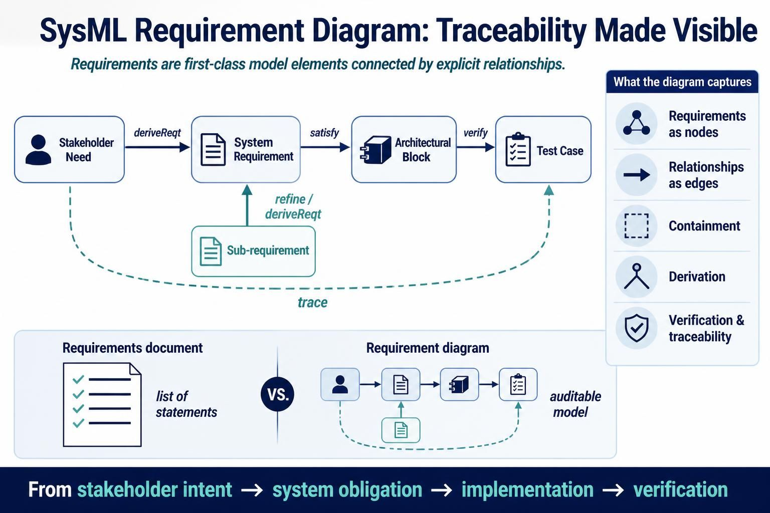
A Requirement Diagram in the Systems Modeling Language (SysML) serves this exact purpose. It captures requirements as first-class model elements and makes their relationships—containment, derivation, satisfaction, verification, and traceability—explicit and auditable. By treating requirements as nodes in a graph rather than lines in a spreadsheet, teams can answer critical questions instantly: Why does this component exist? Is this requirement verified? What is the impact of this change?
This guide explores the core concepts, practical workflows, and tooling support for Requirement Diagrams, specifically leveraging Visual Paradigm and its VPasCode environment to bridge the gap between business needs and technical implementation.
Key Concepts and Notation
Understanding the semantic precision of SysML is essential before drawing a single line. A requirement diagram is defined by two primary constructs: the requirement element itself and the typed relationships that connect it to the rest of the system model.
The Requirement Element
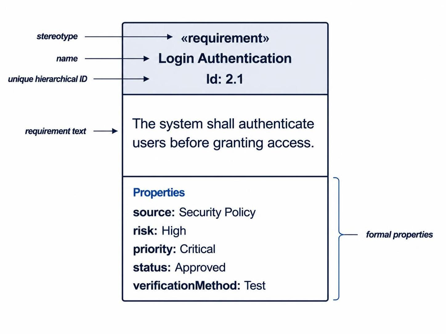
A requirement is represented as a rectangle stereotyped as «requirement». It must contain three core attributes:
-
Name: A concise human-readable label.
-
ID: A unique, typically hierarchical identifier (e.g.,
1.2.3). -
Text: The formal statement of the requirement.
Crucially, requirements should also include properties such as source, risk, priority, status, or verificationMethod. These attributes transform vague aspirations into measurable, queryable model elements.
Core Relationships
The power of a requirement diagram lies in its edges. Each relationship type has a specific semantic meaning that must be respected to maintain model integrity.
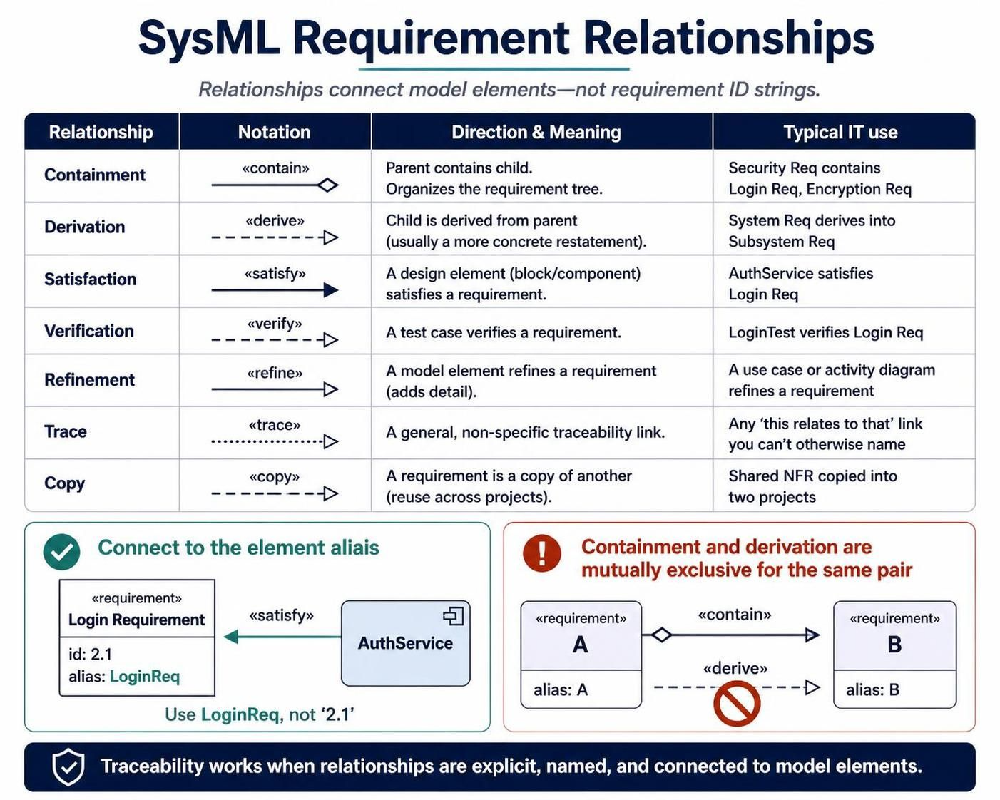
| Relationship | Notation | Direction & Meaning | Typical IT Use |
|---|---|---|---|
| Containment | «contain» |
Parent contains child. Organizes the requirement tree. | Security Req contains Login Req, Encryption Req |
| Derivation | «derive» |
Child is derived from parent (concrete restatement). | System Req derives into Subsystem Req |
| Satisfaction | «satisfy» |
A design element (block) satisfies a requirement. | AuthService satisfies Login Req |
| Verification | «verify» |
A test case verifies a requirement. | LoginTest verifies Login Req |
| Refinement | «refine» |
A model element refines a requirement (adds detail). | A use case refines a requirement |
| Trace | «trace» |
General, non-specific traceability link. | Loose associations not covered by other types |
| Copy | «copy» |
Requirement is a copy of another (reuse). | Shared NFR copied across projects |
Critical Modeling Rule: Relationships always connect to an element’s alias, never to its ID string. Furthermore, containment and derivation are mutually exclusive for the same pair of elements; a child cannot be both contained by and derived from the same parent.
Supporting Elements
Requirements do not exist in a vacuum. They interact with:
-
Blocks (
«block»): Architectural components (services, modules, APIs) that satisfy requirements. -
Test Cases (
«testCase»): Verification units that prove requirements are met. -
Refinement Sources: Use cases, activities, or other diagrams that elaborate on requirement intent.
Practical Examples
The following examples demonstrate how to apply these concepts to real-world IT scenarios using PlantUML syntax compatible with Visual Paradigm’s VPasCode.
Example 1: Foundational Requirement Hierarchy
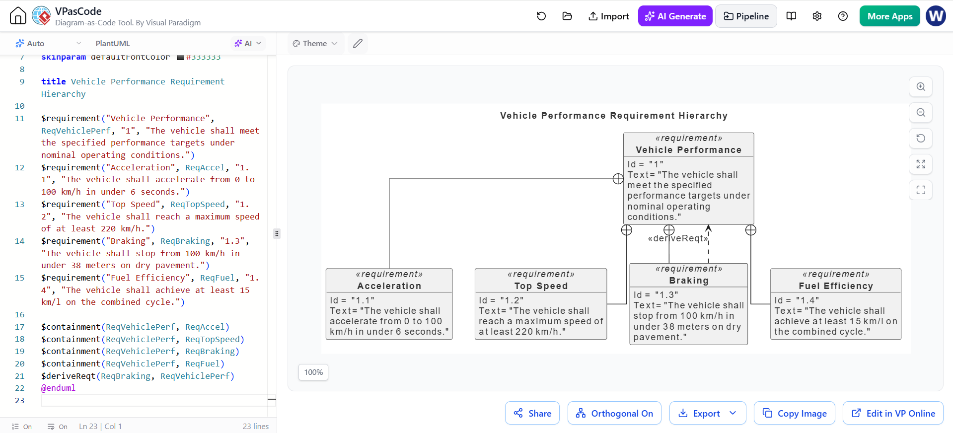
This diagram illustrates the structural decomposition of a high-level performance goal into measurable sub-requirements using containment and derivation.
@startuml
!include https://static.visual-paradigm.com/plantuml-stdlib/sysml-requirement-diagram.puml

skinparam vpDiagramType RequirementDiagram
skinparam defaultFontSize 14
skinparam defaultFontColor #333333
skinparam linetype ortho

title Vehicle Performance Requirement Hierarchy

$requirement("Vehicle Performance", ReqVehiclePerf, "1", "The vehicle shall meet the specified performance targets under nominal operating conditions.")
$requirement("Acceleration", ReqAccel, "1.1", "The vehicle shall accelerate from 0 to 100 km/h in under 6 seconds.")
$requirement("Top Speed", ReqTopSpeed, "1.2", "The vehicle shall reach a maximum speed of at least 220 km/h.")
$requirement("Braking", ReqBraking, "1.3", "The vehicle shall stop from 100 km/h in under 38 meters on dry pavement.")
$requirement("Fuel Efficiency", ReqFuel, "1.4", "The vehicle shall achieve at least 15 km/l on the combined cycle.")

$containment(ReqVehiclePerf, ReqAccel)
$containment(ReqVehiclePerf, ReqTopSpeed)
$containment(ReqVehiclePerf, ReqBraking)
$containment(ReqVehiclePerf, ReqFuel)
$deriveReqt(ReqBraking, ReqVehiclePerf)
@enduml
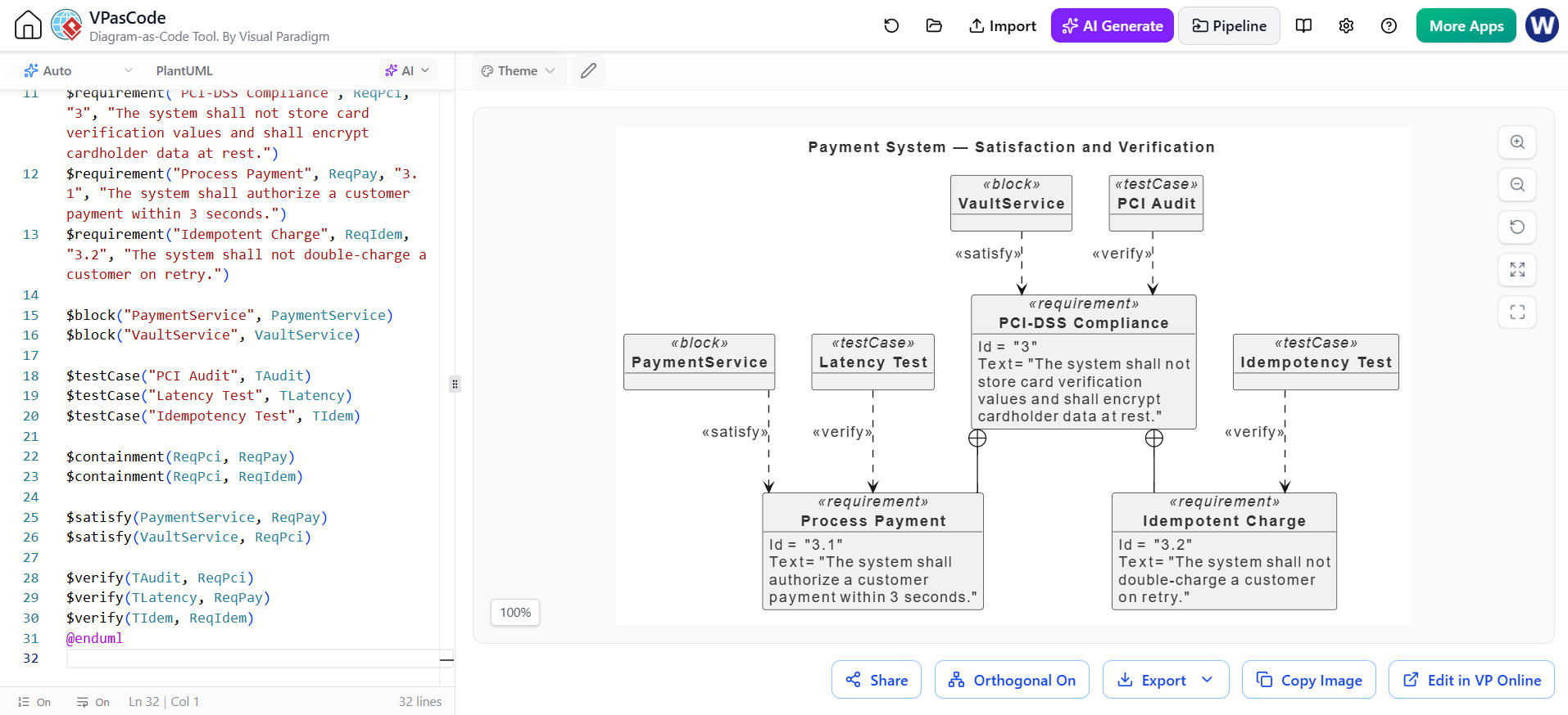
Example 2: Satisfaction and Verification
This example connects the requirements world to the design and testing worlds. It demonstrates how architectural blocks satisfy requirements and how test cases verify them, forming the basis of a design review.
@startuml
!include https://static.visual-paradigm.com/plantuml-stdlib/sysml-requirement-diagram.puml

skinparam vpDiagramType RequirementDiagram
skinparam defaultFontSize 14
skinparam defaultFontColor #333333
skinparam linetype ortho

title Payment System — Satisfaction and Verification

$requirement("PCI-DSS Compliance", ReqPci, "3", "The system shall not store card verification values and shall encrypt cardholder data at rest.")
$requirement("Process Payment", ReqPay, "3.1", "The system shall authorize a customer payment within 3 seconds.")
$requirement("Idempotent Charge", ReqIdem, "3.2", "The system shall not double-charge a customer on retry.")

$block("PaymentService", PaymentService)
$block("VaultService", VaultService)

$testCase("PCI Audit", TAudit)
$testCase("Latency Test", TLatency)
$testCase("Idempotency Test", TIdem)

$containment(ReqPci, ReqPay)
$containment(ReqPci, ReqIdem)

$satisfy(PaymentService, ReqPay)
$satisfy(VaultService, ReqPci)

$verify(TAudit, ReqPci)
$verify(TLatency, ReqPay)
$verify(TIdem, ReqIdem)
@enduml
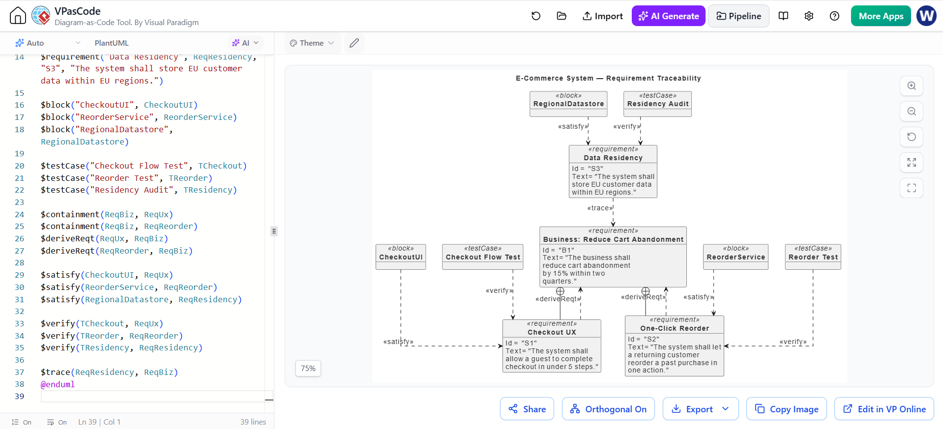
Example 3: Full IT-System Traceability Chain
This comprehensive view traces a business need through system requirements to architectural components and verification tests. It answers the fundamental question: “Why does this code exist?”
@startuml
!include https://static.visual-paradigm.com/plantuml-stdlib/sysml-requirement-diagram.puml

skinparam vpDiagramType RequirementDiagram
skinparam defaultFontSize 14
skinparam defaultFontColor #333333
skinparam linetype ortho

title E-Commerce System — Requirement Traceability

$requirement("Business: Reduce Cart Abandonment", ReqBiz, "B1", "The business shall reduce cart abandonment by 15% within two quarters.")
$requirement("Checkout UX", ReqUx, "S1", "The system shall allow a guest to complete checkout in under 5 steps.")
$requirement("One-Click Reorder", ReqReorder, "S2", "The system shall let a returning customer reorder a past purchase in one action.")
$requirement("Data Residency", ReqResidency, "S3", "The system shall store EU customer data within EU regions.")

$block("CheckoutUI", CheckoutUI)
$block("ReorderService", ReorderService)
$block("RegionalDatastore", RegionalDatastore)

$testCase("Checkout Flow Test", TCheckout)
$testCase("Reorder Test", TReorder)
$testCase("Residency Audit", TResidency)

$containment(ReqBiz, ReqUx)
$containment(ReqBiz, ReqReorder)
$deriveReqt(ReqUx, ReqBiz)
$deriveReqt(ReqReorder, ReqBiz)

$satisfy(CheckoutUI, ReqUx)
$satisfy(ReorderService, ReqReorder)
$satisfy(RegionalDatastore, ReqResidency)

$verify(TCheckout, ReqUx)
$verify(TReorder, ReqReorder)
$verify(TResidency, ReqResidency)

$trace(ReqResidency, ReqBiz)
@enduml
Building Effective Requirement Diagrams
Creating a useful diagram requires discipline beyond just knowing the notation. Follow this workflow to ensure your models remain actionable:
-
Start Top-Down: Begin with business or stakeholder needs. Assign clear ID namespaces (e.g.,
B*for business,S*for system). -
Decompose with Containment: Break high-level needs into measurable sub-requirements. Avoid vague text; always include thresholds or metrics.
-
Apply Derivation Carefully: Use derivation only when a child is a concrete restatement of intent, not merely a structural part. Never combine containment and derivation between the same pair.
-
Map Satisfaction: Ensure every system requirement is satisfied by at least one block. Unsatisfied requirements represent coverage gaps.
-
Map Verification: Ensure every requirement has a corresponding test case. Unverified requirements are untestable wishes.
-
Limit Scope: Keep individual diagrams under ~24 elements. Split by subsystem or concern to maintain readability.
The Coverage Checklist
Validate every diagram against these three questions:
-
Is every system requirement satisfied by a design element?
-
Is every requirement verified by a test case?
-
Does every requirement trace back to a business need?
Any negative answer indicates a model defect that must be resolved.
Tooling: Visual Paradigm and VPasCode
While SysML can be modeled in many tools, Visual Paradigm offers specialized support for requirement diagrams through its VPasCode platform. VPasCode enables a “Diagram-as-Code” workflow where PlantUML source is rendered directly into compliant SysML diagrams with automatic layout and styling.
Key advantages include:
-
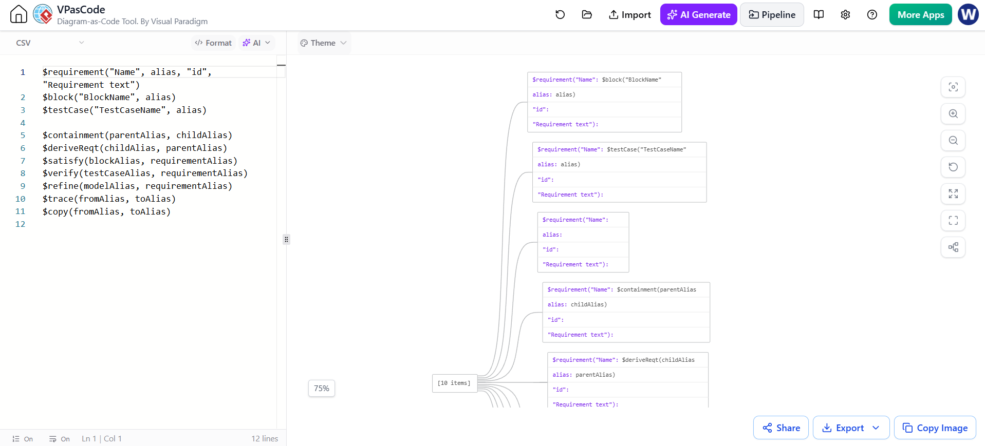
Native SysML Support: Pre-built macros for requirements, blocks, test cases, and all standard relationships.
-
AI-Assisted Generation: Natural language prompts can generate initial diagram structures, which can then be refined manually.
-
Live Preview & Export: Real-time rendering with export to SVG, PNG, and PDF for documentation.
-
Version Control Friendly: Text-based source files integrate seamlessly with Git workflows.
Common Pitfalls to Avoid
-
Confusing Derivation and Containment: They are semantically distinct. Mixing them invalidates the model.
-
Referencing IDs Instead of Aliases: Tools bind relationships to aliases. Incorrect aliases create silent broken links.
-
Overusing
«trace»: Reserve it for loose associations. If a component implements a requirement, use«satisfy». -
Non-Measurable Requirements: “Fast” or “user-friendly” cannot be verified. Always quantify.
-
Diagrams as Specs: The diagram shows structure; the requirement text and properties carry the detail. Keep text precise.
Conclusion
A Requirement Diagram is far more than a visual aid; it is the traceability backbone of systems engineering. For IT projects plagued by drift and misalignment, it provides the rigorous structure needed to connect business intent to technical reality. By mastering the semantic distinctions between containment, derivation, satisfaction, and verification—and by leveraging modern tooling like Visual Paradigm’s VPasCode—teams can transform requirements from static documents into living, queryable models. The result is not just better documentation, but better systems: ones that are verifiably aligned with stakeholder needs, resilient to change, and auditable from concept to code.
References
- VPasCode: AI-Assisted Diagram-as-Code with PlantUML, Mermaid, and Graphviz: Official guide covering AI-assisted diagram generation, modification workflows, and multi-DSL support including PlantUML, Mermaid, and Graphviz.
- Visual Paradigm VPasCode: Comprehensive Guide: Detailed overview of VPasCode features, target users (developers, architects, analysts), and its role in Agile documentation workflows.
- Welcome to Visual Paradigm VPasCode: The Shift to Diagram-as-Code (DaC): Introduction to the unified platform, explaining the advantages of text-to-diagram workflows and automated layout engineering.
- 60-Second Quickstart Guide | VPasCode Text to Diagram Guide: Step-by-step walkthrough for creating, customizing, and exporting diagrams using the browser-based editor with live preview.
- New in VPasCode: AI UML Profile Diagram Generator: Product update introducing AI-powered UML Profile Diagram generation using plain English prompts, with example for healthcare data privacy compliance.
- Native AI Diagram Generation in Visual Paradigm VPasCode: Announcement of embedded AI capabilities for generating, modifying, and fixing diagrams via natural language prompts directly in the editor.
- AI-Powered Diagram Generator & Productivity Tools | VPasCode: Overview of VPasCode integrations with AI chatbots, Visual Paradigm Desktop, and OpenDocs for streamlined documentation pipelines.
- Best PlantUML Alternatives & Free Diagram as Code Editors: Comparison matrix of PlantUML alternatives, highlighting VPasCode’s multi-DSL support, AI features, and browser-based zero-setup approach.
- Diagram-as-Code Editor: Convert Text to Diagram Instantly: Feature overview covering automatic format detection, real-time rendering, and multi-format export options (SVG, PNG, PDF).
- Guide to the Visual Paradigm Ecosystem: Explains when to use VPasCode vs. VP Desktop, with guidance on version-controlled diagram maintenance and integration with living documentation.
Related posts:
 Diagram-as-Code in Your Editor: A Complete Guide to AI Generation in VPasCode
Effortless UML Refinement: A Step-by-Step Guide to Modifying Class Diagrams with VPasCode’s Embedded AI
Diagram-as-Code in Your Editor: A Complete Guide to AI Generation in VPasCode
Effortless UML Refinement: A Step-by-Step Guide to Modifying Class Diagrams with VPasCode’s Embedded AI
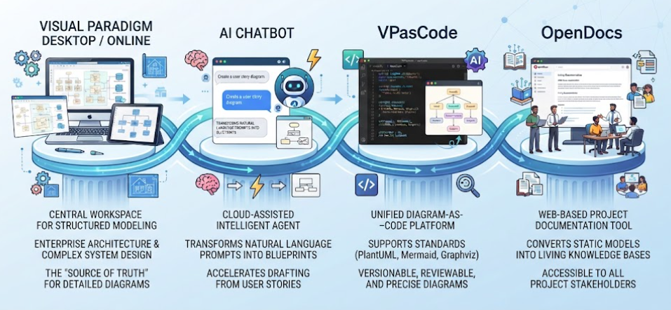 Visual Paradigm’s Unified Platform At a Glance
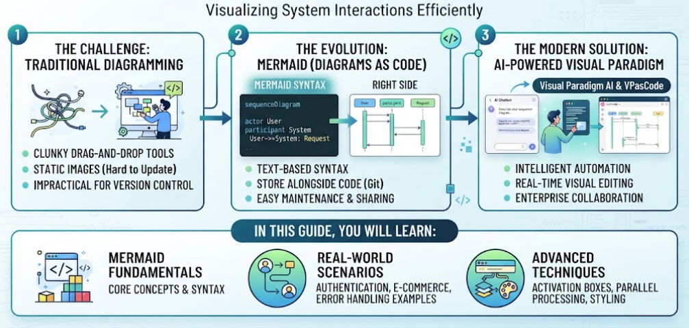 Comprehensive Guide to Sequence Diagrams with Diagram as Code using Mermaid with VPasCode and VP AI Chatbot