
Introduction
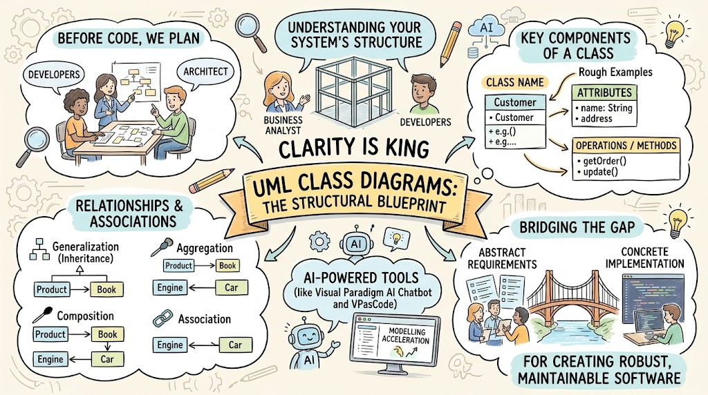
In the complex world of software engineering, clarity is king. Before a single line of code is written, developers and architects must agree on the structural blueprint of the system they are building. This is where the UML Class Diagram becomes indispensable.
As a type of static structure diagram within the Unified Modeling Language (UML), the class diagram describes the system’s structure by showing its classes, their attributes, operations (methods), and the relationships among objects. It serves as the backbone for object-oriented design, bridging the gap between abstract requirements and concrete implementation.
Whether you are a Business Analyst modeling domain concepts or a Developer defining specific interfaces, understanding class diagrams is essential for creating robust, maintainable software. This guide will walk you through the core components, relationships, and best practices of class diagrams, leveraging modern AI-powered tools like Visual Paradigm AI Chatbot and VPasCode to accelerate your modeling workflow.
What is a Class Diagram?
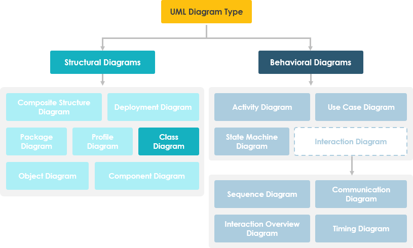
A class diagram provides a visual representation of the static view of a system. Unlike behavioral diagrams (like Sequence or Activity diagrams) that show how things happen, class diagrams show what exists in the system.
Purpose of Class Diagrams
- Static Structure Visualization: Shows the classifiers (classes, interfaces) and their static relationships.
- Foundation for Other Diagrams: Provides the basic notation for other structure diagrams prescribed by UML.
- Cross-Functional Communication: Helpful for developers, testers, and stakeholders to understand system architecture.
- Business Modeling: Business Analysts can use them to model systems from a business perspective, independent of technical implementation.
A UML class diagram consists of two main elements:
- A set of Classes
- A set of Relationships between those classes
The Building Block: What is a Class?
A class is a description of a group of objects with similar roles in the system. It acts as a blueprint for creating objects. A class consists of two primary types of features:
- Structural Features (Attributes): Define what objects of the class “know.” They represent the state of an object and describe static features.
- Behavioral Features (Operations): Define what objects of the class “can do.” They define how objects interact and describe dynamic features.
Class Notation
A standard class notation is divided into three partitions:
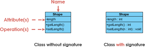
- Class Name: Appears in the first partition.
- Class Attributes: Shown in the second partition. The attribute type is shown after the colon (
:). These map to member variables in code. - Class Operations (Methods): Shown in the third partition. These are services the class provides. The return type is shown after the colon at the end of the signature. Parameters also include their types after the colon.
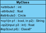
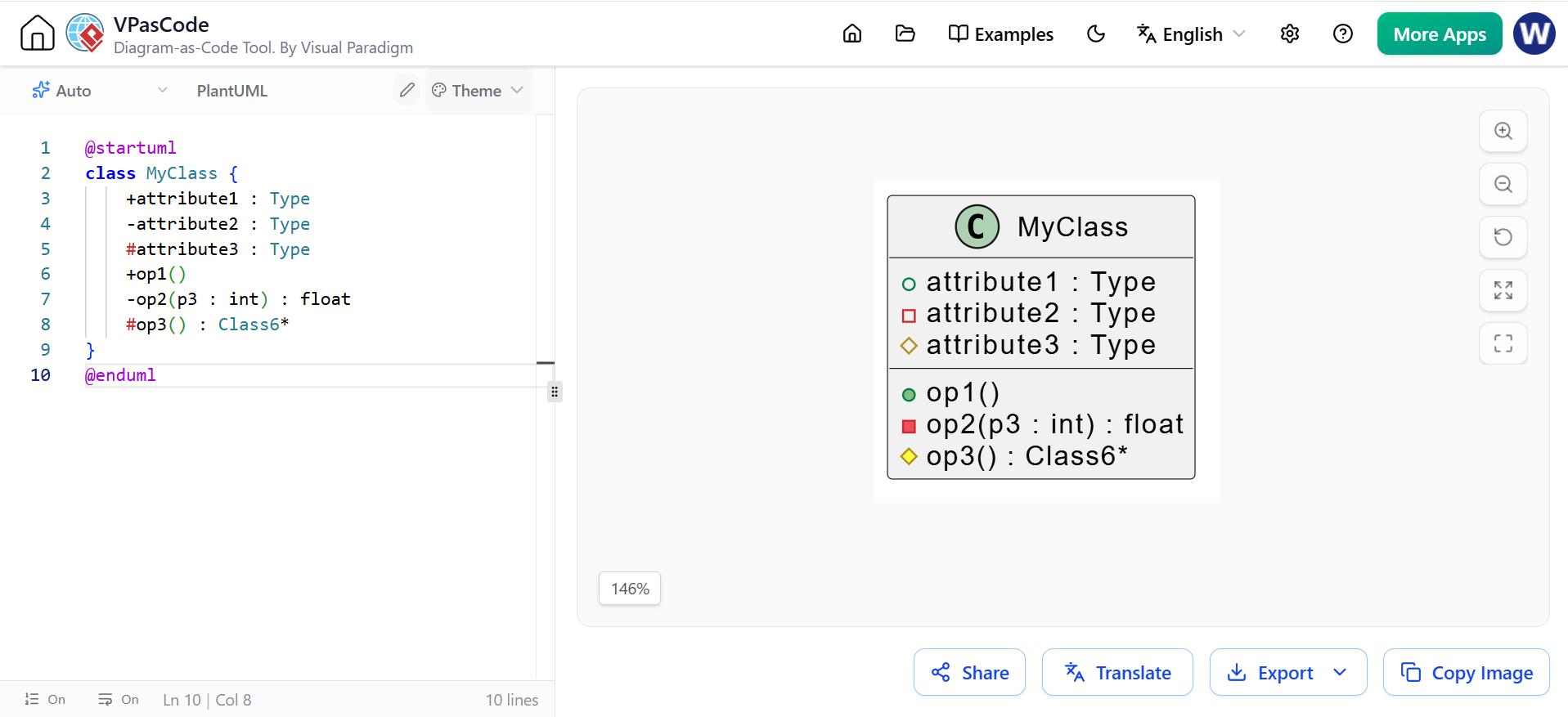
Interpreting the Example Above:
- MyClass has 3 attributes and 3 operations.
- Parameter
p3of operationop2is of typeint. - Operation
op2returns afloat. - Operation
op3returns a pointer (denoted by*) toClass6.
Modern Modeling with PlantUML
While traditional tools use drag-and-drop interfaces, modern developers often prefer “Diagrams as Code.” Here is how the simple class above would be represented in PlantUML:
@startuml
class MyClass {
    +attribute1 : Type
    -attribute2 : Type
    #attribute3 : Type
    +op1()
    -op2(p3 : int) : float
    #op3() : Class6*
}
@enduml
Class Relationships
Classes rarely exist in isolation. They interact through various relationships. Understanding these connections is crucial for accurate modeling.
| Relationship Type | Graphical Representation | Description |
|---|---|---|
| Inheritance (Generalization) | 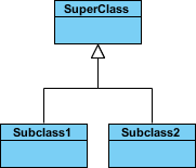 |
Represents an “is-a” relationship. A solid line with a hollow arrowhead points from the child (subclass) to the parent (superclass). Abstract classes are shown in italics. |
| Simple Association |  |
A structural link between two peer classes. Represented by a solid line connecting two classes. |
| Aggregation |  |
A “part-of” relationship where parts have separate lifetimes. Represented by a solid line with an unfilled diamond at the composite end. |
| Composition |  |
A strong form of aggregation where parts are destroyed when the whole is destroyed. Represented by a solid line with a filled diamond at the composite end. |
| Dependency |  |
Exists if changes to one class affect another. Represented by a dashed line with an open arrow pointing to the dependent class. |
Relationship Names and Roles
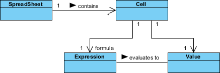
- Names: Written in the middle of the association line. Good names make sense when read aloud (e.g., “Spreadsheet contains Cells”). Small arrowheads indicate reading direction.
- Roles: Written at the ends of an association line, describing the purpose played by that class (e.g., An expression is the formula of a cell).
Navigability
Arrows indicate whether, given one instance, you can determine the related instances of the other class.
- If an arrow points from A to B, you can navigate from A to B.
- In the example above, given a Spreadsheet, we can locate its Cells, but given a Cell, we cannot necessarily determine which Spreadsheet it belongs to.
Visibility Modifiers
In object-oriented design, visibility controls access to attributes and operations. UML uses four symbols:
+Public: Accessible by any class.-Private: Accessible only within the same class.#Protected: Accessible within the same class and derived classes.~Package: Accessible within the same package.
Access Rights Table:
| Access Right | Public (+) | Private (-) | Protected (#) | Package (~) |
|---|---|---|---|---|
| Same Class | Yes | Yes | Yes | Yes |
| Derived Classes | Yes | No | Yes | Yes |
| Other Classes | Yes | No | No | In same package |
Multiplicity
Multiplicity defines how many objects of each class participate in a relationship.
1: Exactly one0..1: Zero or one*or0..*: Many (zero or more)1..*: One or more3..4: Exact range (e.g., 3 to 4)
Multiplicity Example
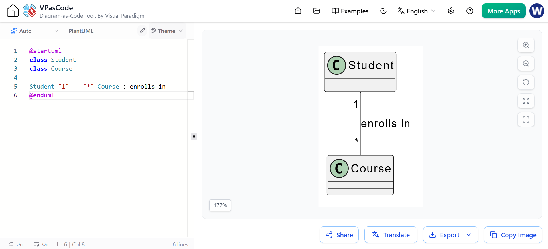
Requirement: A Student can take many Courses, and many Students can be enrolled in one Course.

The class diagram (left) models this statically, while the object diagram (right) shows a snapshot of specific instances.
PlantUML Representation:
@startuml
class Student
class Course

Student "1" -- "*" Course : enrolls in
@enduml
Practical Examples
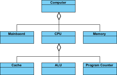
Aggregation: Computer and Parts
Aggregation denotes a “consists-of” hierarchy where the parts can exist independently of the whole.
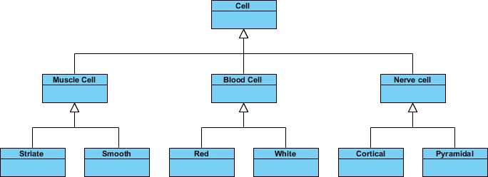
Inheritance: Cell Taxonomy
Inheritance simplifies models by introducing a taxonomy. Child classes inherit attributes and operations from the parent.
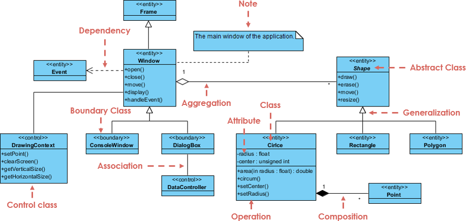
Comprehensive Class Diagram Example
Below is a complete example illustrating multiple concepts: abstract classes, inheritance, aggregation, composition, and dependency.
Key Interpretations:
- Shape is an abstract class (shown in italics).
- Circle, Rectangle, Polygon are subclasses of Shape (Inheritance).
- DialogBox and DataController have an Association.
- Shape is part of Window (Aggregation); Shapes can exist without the Window.
- Point is part of Circle (Composition); Points cannot exist without the Circle.
- Window depends on Event (Dependency).
- Circle has attributes
radiusandcenter, and methods likearea()andsetRadius().
PlantUML Code for this Complex Diagram:
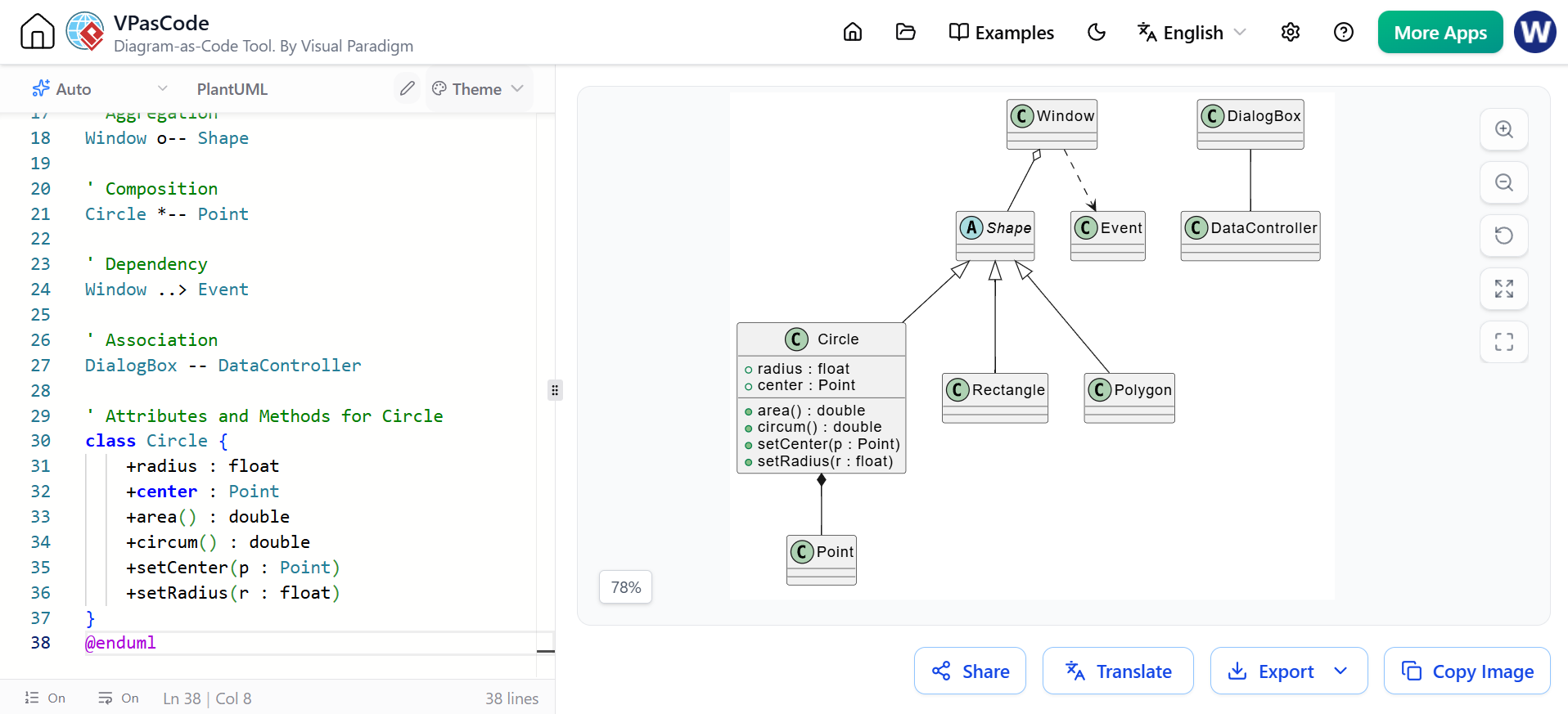
@startuml
abstract class Shape
class Circle
class Rectangle
class Polygon
class Window
class Point
class DialogBox
class DataController
class Event

' Inheritance
Shape <|-- Circle
Shape <|-- Rectangle
Shape <|-- Polygon

' Aggregation
Window o-- Shape

' Composition
Circle *-- Point

' Dependency
Window ..> Event

' Association
DialogBox -- DataController

' Attributes and Methods for Circle
class Circle {
    +radius : float
    +center : Point
    +area() : double
    +circum() : double
    +setCenter(p : Point)
    +setRadius(r : float)
}
@enduml
Accelerate Class Diagramming with Visual Paradigm AI
Building robust static structures doesn’t have to start from a blank canvas. Modern tools like Visual Paradigm integrate AI to streamline the process.
Multi-Platform AI Support
- VP Desktop: Generate Class Diagrams via AI and refine them using professional modeling suites.
- AI Chatbot: Simply describe your domain (e.g., “Create a class diagram for a library system with Books, Members, and Loans”) and let the AI Chatbot generate the structure.
- OpenDocs: Embed AI-generated Class Diagrams directly into your OpenDocs for live documentation.
Specialized Class Diagram Apps
- ⚡ AI Class Diagram Wizard: Step-by-step assistant for defining classes, attributes, and operations.
- 🔄 Use Case Studio: Automatically extracts domain classes from behavioral use case descriptions.
- 🚀 Agilien: Bridges User Stories and Epics directly to structural UML models.
- 💾 DB Modeler AI: Generates conceptual Domain Class Diagrams specifically for database design.
- 🏛️ MVC Architecture: Generates specialized Controller Class Diagrams for web applications.
Explore how to master Class Diagrams with AI:
AI Class Diagram Guide | Full AI Ecosystem
Dealing with Complex Systems
When modeling large systems, should you use a single massive diagram or multiple smaller ones?
Recommendation: Use multiple class diagrams.
Dividing a system into multiple diagrams, each representing a specific subsystem or module, makes the architecture easier to understand and maintain. A single monolithic diagram often becomes unreadable and difficult to update.
Perspectives in the Software Development Lifecycle
Class diagrams evolve as the project progresses. We typically model them from three perspectives:
- Conceptual Perspective:
- Describes things in the real world.
- Focuses on domain concepts rather than software classes.
- Language-independent. Used during early analysis.
- Specification Perspective:
- Describes software abstractions, interfaces, and specifications.
- No commitment to a specific implementation language.
- Focuses on interfaces rather than internal logic.
- Implementation Perspective:
- Describes actual software implementations in a specific technology (e.g., Java, C#).
- Includes detailed visibility, data types, and framework-specific classes.
- Focuses on code structure.
Conclusion
UML Class Diagrams are more than just boxes and lines; they are a powerful communication tool that aligns stakeholders, developers, and architects. By mastering the notation of classes, relationships, visibility, and multiplicity, you can create clear blueprints that reduce ambiguity and technical debt.
With the advent of AI-driven tools like Visual Paradigm’s AI Chatbot and code-based approaches like PlantUML, creating and maintaining these diagrams has never been more efficient. Whether you are starting from a conceptual idea or refining an existing codebase, class diagrams remain a cornerstone of effective software engineering.
Related posts:
 Comprehensive Guide: From Problem Statement to Class Diagram, ERD, and Database Modeling with Visual Paradigm
 Visual Paradigm’s AI‑Powered ERD Generator
 How Visual Paradigm’s AI Diagram Generation Turns Your Ideas into Professional UML & BPMN Diagrams in Seconds
 Why Teams Are Switching to Visual Paradigm: Powerful Modeling Meets Cutting-Edge AI