
Introduction
In the complex world of software architecture and business process modeling, clarity is king. While static diagrams like Class Diagrams show us what a system is made of, Activity Diagrams reveal how it behaves. They are the dynamic heartbeat of UML (Unified Modeling Language), capturing the flow of control and data from initiation to completion.
Think of an Activity Diagram as a sophisticated flowchart designed for enterprise logic. It doesn’t just list steps; it visualizes decision points, parallel processes, loops, and hand-offs between different actors or systems. Whether you are documenting a user’s login journey, mapping out an order fulfillment pipeline, or designing a complex algorithm, Activity Diagrams provide a universal language that bridges the gap between business stakeholders and technical teams.
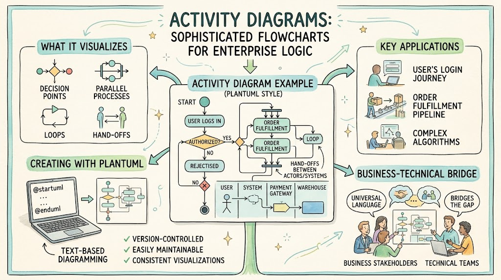
This guide focuses on creating these powerful diagrams using PlantUML, a text-based diagramming tool that allows for version-controlled, easily maintainable, and consistent visualizations. By mastering the syntax and best practices outlined below, you will be able to transform abstract processes into clear, actionable visual models.
1. Key Concepts & Building Blocks
Every robust Activity Diagram is constructed from a specific set of core elements. Understanding these building blocks is essential before writing any code.
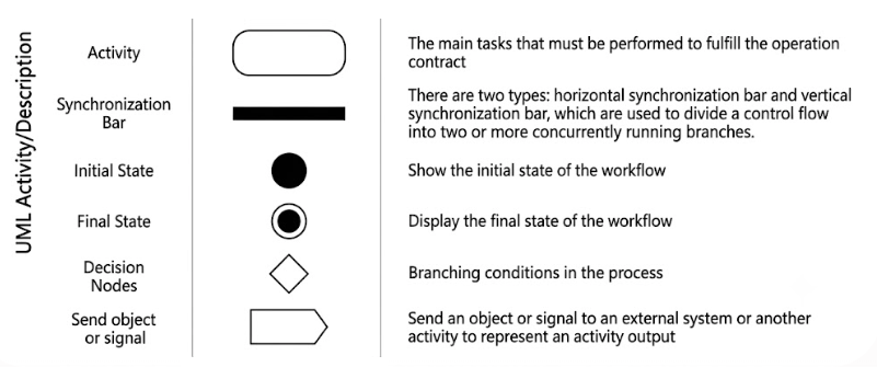
| Element | Shape | Purpose |
|---|---|---|
| Start Node | ● | Marks where the flow begins (mandatory) |
| Action / Activity | ▭ rounded | A single step or task in the process |
| Decision / Merge | ◇ | A branching condition (yes/no or multi-way) |
| Loop (Repeat) | ◇→◇ | Repeats an action until a condition is met |
| Fork / Join | — | Splits flow into parallel branches and joins them back |
| Swimlane | Table column | Groups activities by responsible actor / system / department |
| Stop Node | ◉ | Marks where the flow ends (at least one required) |
Key Terminologies
- Action: An atomic step in the process, e.g.,
:Validate Payment;. - Control Flow: The arrows connecting actions, indicating the sequence of execution.
- Decision Node: Evaluates a guard condition to determine which path to take next.
- Fork/Join: A Fork activates concurrent flows (parallel processing), while a Join synchronizes them back into a single thread.
- Swimlane: Partitions the diagram by responsibility. This is excellent for showing hand-offs between departments, users, or microservices.
2. Diagram Examples
Below are two comprehensive examples demonstrating how to combine these elements into functional diagrams.
Example A: Full-featured “Order Processing”
Features: Swimlanes, Decisions, Loops, and Forks
This diagram models a complete e-commerce order lifecycle, involving a Customer, an Order System, and a Warehouse.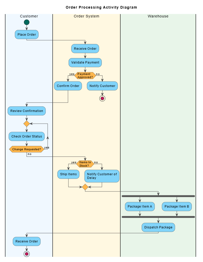
@startuml
<style>
  element { MaximumWidth 150 }
  start   { Backgroundcolor #00695C }
  stop    { Backgroundcolor #C2185B }
  activity{ Backgroundcolor #81D4FA; MaximumWidth 150 }
  diamond { Backgroundcolor #FFB74D; MaximumWidth 80 }
  arrow   { LineColor #424242; Fontcolor #000000 }
  swimlane{ Fontcolor #000000; FontSize 14 }
</style>
title Order Processing Activity Diagram

|#F0F8FF|Customer|
start
:Place Order;

|#FFF8E1|Order System|
:Receive Order;
:Validate Payment;

if (Payment Approved?) then (yes)
  :Confirm Order;
else (no)
  :Notify Customer;
  stop
endif

|#F0F8FF|Customer|
:Review Confirmation;

repeat
  :Check Order Status;
repeat while (Change Requested?) is (yes) not (no)

|#FFF8E1|Order System|
if (Items In Stock?) then (yes)
  :Ship Items;
else (no)
  :Notify Customer of Delay;
endif

|#E8F5E9|Warehouse|
fork
  :Package Item A;
fork again
  :Package Item B;
end fork
:Dispatch Package;

|#F0F8FF|Customer|
:Receive Order;
stop
@enduml
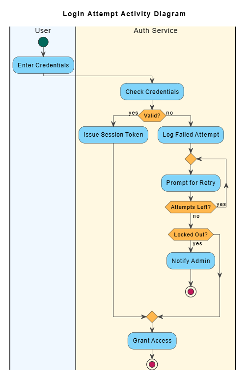
Example B: Focused “Login Attempt”
Features: Decisions, Loops, and Early Termination
This diagram focuses on security logic, handling valid credentials, failed attempts, retries, and account lockouts.
@startuml
<style>
  element { MaximumWidth 150 }
  start   { Backgroundcolor #00695C }
  stop    { Backgroundcolor #C2185B }
  activity{ Backgroundcolor #81D4FA; MaximumWidth 150 }
  diamond { Backgroundcolor #FFB74D; MaximumWidth 80 }
  arrow   { LineColor #424242; Fontcolor #000000 }
  swimlane{ Fontcolor #000000; FontSize 14 }
</style>
title Login Attempt Activity Diagram

|#F0F8FF|User|
start
:Enter Credentials;

|#FFF8E1|Auth Service|
:Check Credentials;

if (Valid?) then (yes)
  :Issue Session Token;
else (no)
  :Log Failed Attempt;

  repeat
    :Prompt for Retry;
  repeat while (Attempts Left?) is (yes) not (no)

  if (Locked Out?) then (yes)
    :Notify Admin;
    stop
  endif
endif

:Grant Access;
stop
@enduml
3. PlantUML Syntax Cheat Sheet
Use this reference guide to construct your own diagrams efficiently.
' Start / Stop (mandatory)
start
stop

' Simple action (colon syntax — always include ; )
:Do Something;

' Decision (the ONLY valid form)
if (Condition?) then (yes)
  :Action A;
else (no)
  :Action B;
endif

' Loop
repeat
  :Repeatable Action;
repeat while (Continue?) is (yes) not (no)

' Parallel fork / join
fork
  :Parallel Path A;
fork again
  :Parallel Path B;
end fork
:Join & Continue;

' Swimlanes (define lane, then switch back)
|#F0F8FF|Sales|
:Activity in Sales;
|#FFF8E1|IT|
:Activity in IT;
4. Guidelines & House Rules
To ensure your diagrams are renderable, readable, and professional, adhere to these ten rules:
- Mandatory Start/Stop: Always begin with
startand ensure every possible path reaches astop. A diagram without a destination is incomplete. - Close Decisions: Always terminate decision blocks with
endif. The diagram will fail to render correctly otherwise. - Pair Loops: Every
repeatmust have a matchingrepeat while. They are inseparable syntactic pairs. - Colon Syntax: Use the
:action;format. Do not use legacy shorthand like-> action ->. - Verb-Noun Naming: Name actions clearly using verb-noun pairs (e.g., “Validate Payment” rather than just “Payment”) for better readability.
- Style Placement: Place the
<style>block immediately after@startuml, followed by thetitle. - Use Swimlanes: For any process involving more than one actor, system, or department, use swimlanes to map responsibility clearly.
- Limit Width: Keep activities below ~150px width (using
MaximumWidth) to prevent labels from becoming unreadable. - Avoid Notes: Unless explicitly requested, avoid using note elements to keep the diagram clean and focused on flow.
- Meaningful Labels: Choose descriptive branch labels. While
yes/nois acceptable, labels likeapproved/rejectedorin stock/out of stockprovide immediate context.
5. Tips & Tricks
- Color Code Swimlanes: Use distinct background tints for each swimlane (as seen in the examples). This improves scannability and helps viewers instantly identify who is responsible for which step.
- Fork Only for Parallelism: Use
forkonly when tasks are genuinely independent and can happen simultaneously (e.g., packaging two different items). Do not use forks for sequential steps. - Model Retries Explicitly: Place loops after failure cases to model retry logic clearly. This makes error handling paths obvious to developers and testers.
- Natural Reading Flow: Order actions top-to-bottom. Keep swimlanes in a consistent left-to-right order based on the process flow (e.g., Customer → System → Warehouse).
- Complex Branching: If you need multi-way branching, you can use
elseif, but keep it readable. For complex logic, nestedifstatements are often clearer.
6. Common Use Cases
Activity Diagrams are versatile tools applicable across various domains:
- Business Process Modeling: Documenting order fulfillment, employee onboarding, or approval workflows.
- Use-Case Detailing: Expanding high-level use cases into step-by-step behavioral models.
- Algorithmic Design: Documenting the control flow of complex functions, services, or data processing pipelines.
- Workflow Analysis: Visualizing hand-offs between teams to identify bottlenecks or unclear responsibilities.
- Error Handling: Mapping out fallback mechanisms, retry loops, and failure exits.
- Concurrency Analysis: Identifying where parallel paths need synchronization (fork/join) to prevent race conditions.
- Pattern Compliance: Comparing an actual implemented process against a target standard or regulatory requirement.
7. Who Should Use It?
| Role | Why it helps them |
|---|---|
| Business Analysts | Document and re-engineer business workflows with clear swimlanes to identify inefficiencies. |
| Software Architects | Model service control flow and integrate behavior models with structural diagrams (Class/Sequence). |
| Developers | Design and communicate complex algorithms, state logic, and retry flows before coding. |
| Product Owners / Managers | Align stakeholders on process steps, decision points, and user journeys. |
| QA & Testers | Derive comprehensive test scenarios from branches, loops, and parallel paths. |
| DevOps / SRE | Document deployment pipelines, failure handling strategies, and operational runbooks. |
| Students / Educators | Teach and learn structured design principles and UML behavior modeling. |
✅ Quick Checklist Before You Share a Diagram
Before finalizing your diagram, run through this quality assurance checklist:
- Is
startpresent, and does every path reach astop? - Are all decisions closed with
endif? - Are loops formed with matching
repeat/repeat whilepairs? - Are forks opened with
fork/fork againand closed withend fork? - Does every action end with a semicolon
;? - Are swimlanes used when multiple actors are involved?
- Is the
<style>block andtitleplaced correctly at the top?
Conclusion
UML Activity Diagrams are more than just pretty pictures; they are essential tools for communication, analysis, and design. By leveraging PlantUML, you gain the ability to create these diagrams as code—making them version-controllable, easy to update, and consistent across your organization.
Whether you are mapping a simple user login or a complex distributed supply chain, the principles remain the same: define your start and end points, clarify your decisions, respect parallelism, and assign responsibility through swimlanes. With the syntax cheat sheet and best practices provided in this guide, you are now equipped to model any process with precision and clarity. Start diagramming today, and turn complex logic into understandable workflows.
Related posts:
 Comprehensive Guide: From Problem Statement to Class Diagram, ERD, and Database Modeling with Visual Paradigm
 Visual Paradigm’s AI‑Powered ERD Generator
 How Visual Paradigm’s AI Diagram Generation Turns Your Ideas into Professional UML & BPMN Diagrams in Seconds
 Why Teams Are Switching to Visual Paradigm: Powerful Modeling Meets Cutting-Edge AI