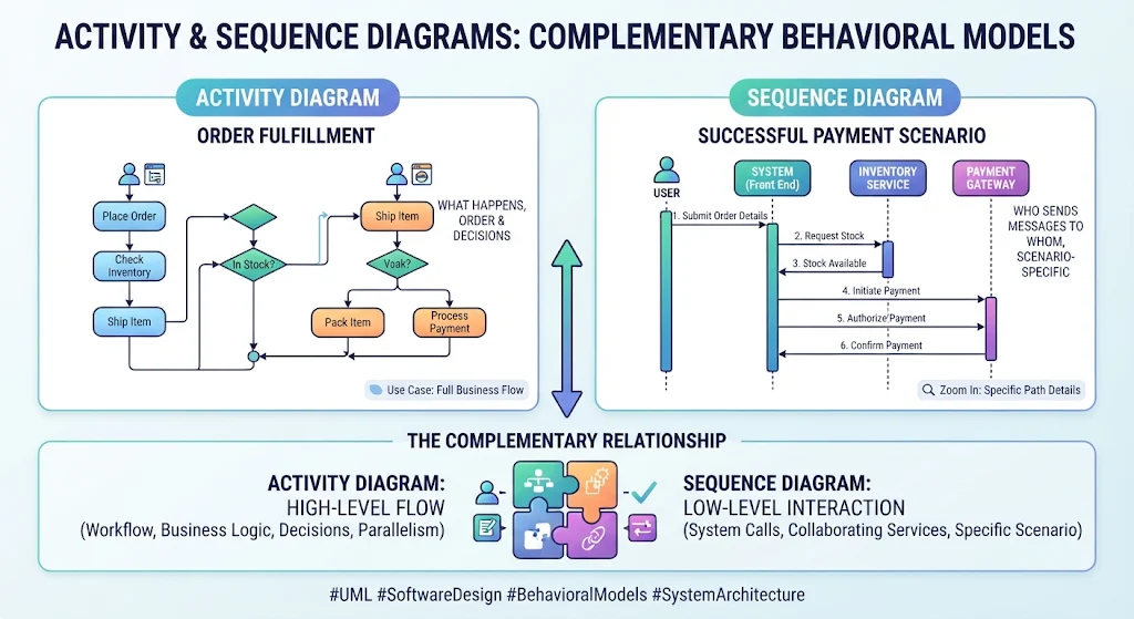
Activity and sequence diagrams both describe behavior, but from different angles:
-
Activity diagram: shows the workflow—what steps happen, in what order, and where decisions or parallel work occur.
-
Sequence diagram: shows the interactions—who sends messages to whom, and in what order, during a particular scenario.
They complement each other. An activity diagram can explain the full business or use-case flow; a sequence diagram can zoom in on how a specific path is carried out by the user, system, and collaborating services.
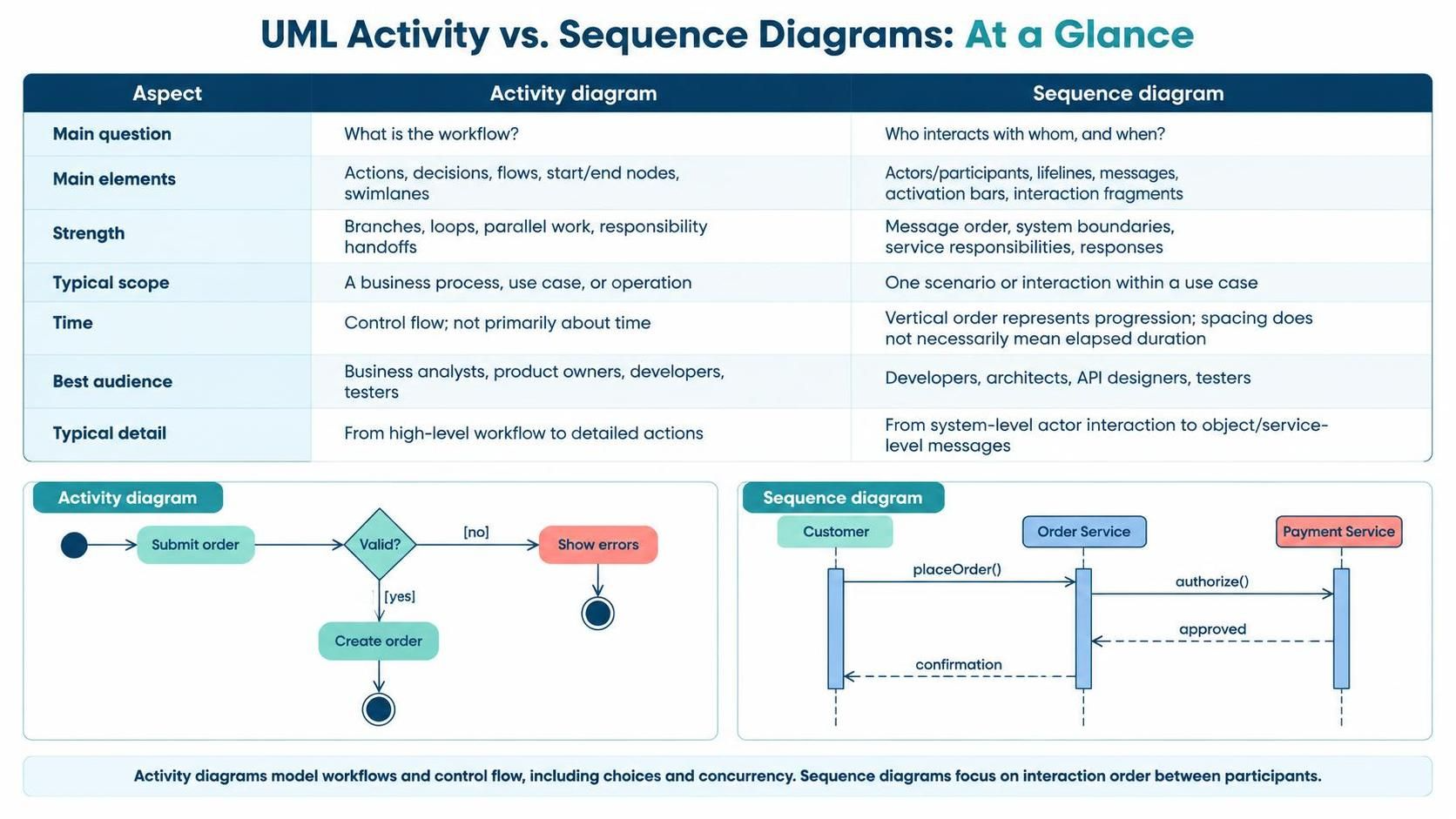
At a glance
| Aspect | Activity diagram | Sequence diagram |
|---|---|---|
| Main question | “What is the workflow?” | “Who interacts with whom, and when?” |
| Main elements | Actions, decisions, flows, start/end nodes, swimlanes | Actors/participants, lifelines, messages, activation bars, interaction fragments |
| Strength | Branches, loops, parallel work, responsibility handoffs | Message order, system boundaries, service responsibilities, responses |
| Typical scope | A business process, use case, or operation | One scenario or interaction within a use case |
| Time | Control flow; not primarily about time | Vertical order represents progression; spacing does not necessarily mean elapsed duration |
| Best audience | Business analysts, product owners, developers, testers | Developers, architects, API designers, testers |
| Typical detail | From high-level workflow to detailed actions | From system-level actor interaction to object/service-level messages |
Activity diagrams model workflows and control flow, including choices and concurrency. Sequence diagrams focus on interaction order between participants.
Key concepts
Activity diagrams
-
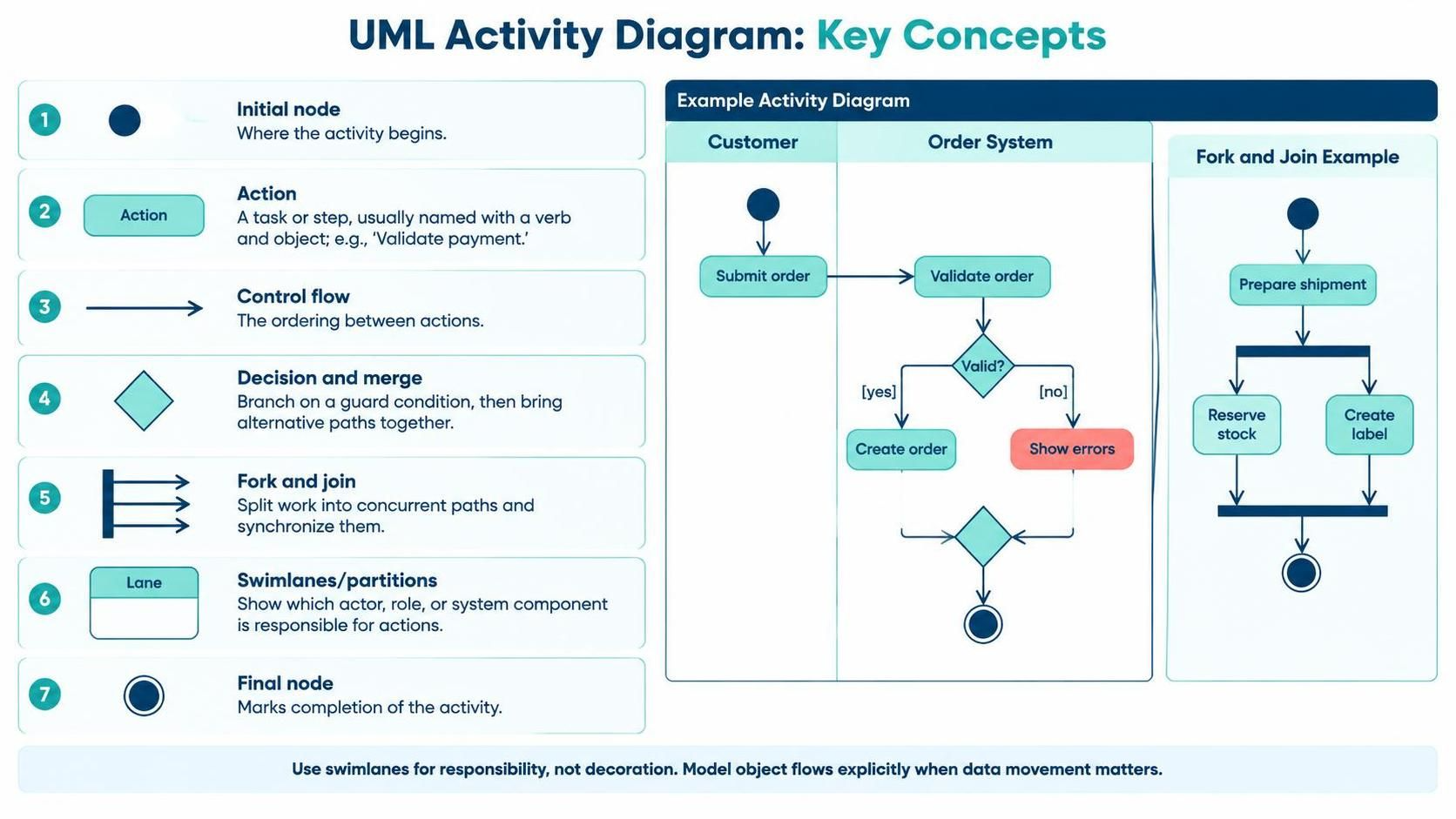
Initial node: where the activity begins.
-
Action: a task or step, usually named with a verb and object, such as “Validate payment.”
-
Control flow: the ordering between actions.
-
Decision and merge: branch on a guard condition, then bring alternative paths together.
-
Fork and join: split work into concurrent paths and synchronize them.
-
Swimlanes/partitions: show which actor, role, or system component is responsible for actions.
-
Final node: marks completion of the activity.
Use swimlanes for responsibility, not merely to decorate the diagram. If the focus is on the flow of data objects between actions, consider modeling object flows explicitly.
Sequence diagrams
-
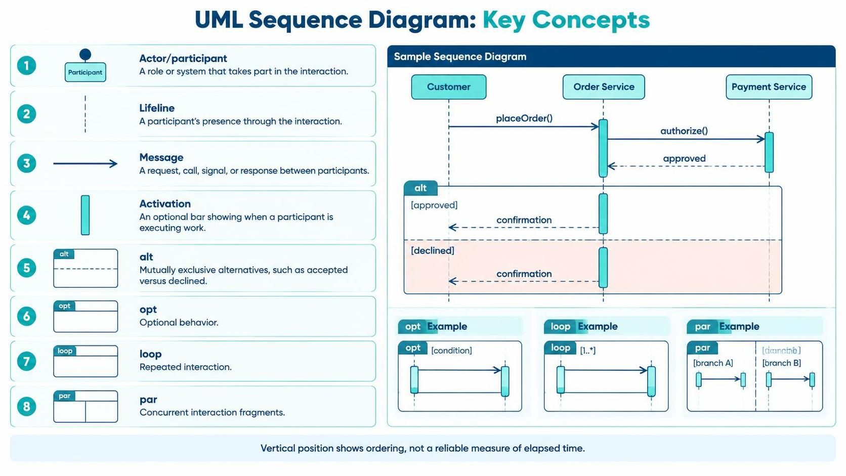
Actor/participant: a role or system that takes part in the interaction.
-
Lifeline: a participant’s presence through the interaction.
-
Message: a request, call, signal, or response between participants.
-
Activation: an optional bar showing when a participant is executing work.
-
alt: mutually exclusive alternatives, such as accepted versus declined. -
opt: optional behavior. -
loop: repeated interaction. -
par: concurrent interaction fragments.
A sequence diagram’s vertical axis shows ordering, not a reliable measure of elapsed time.
Example: placing an order
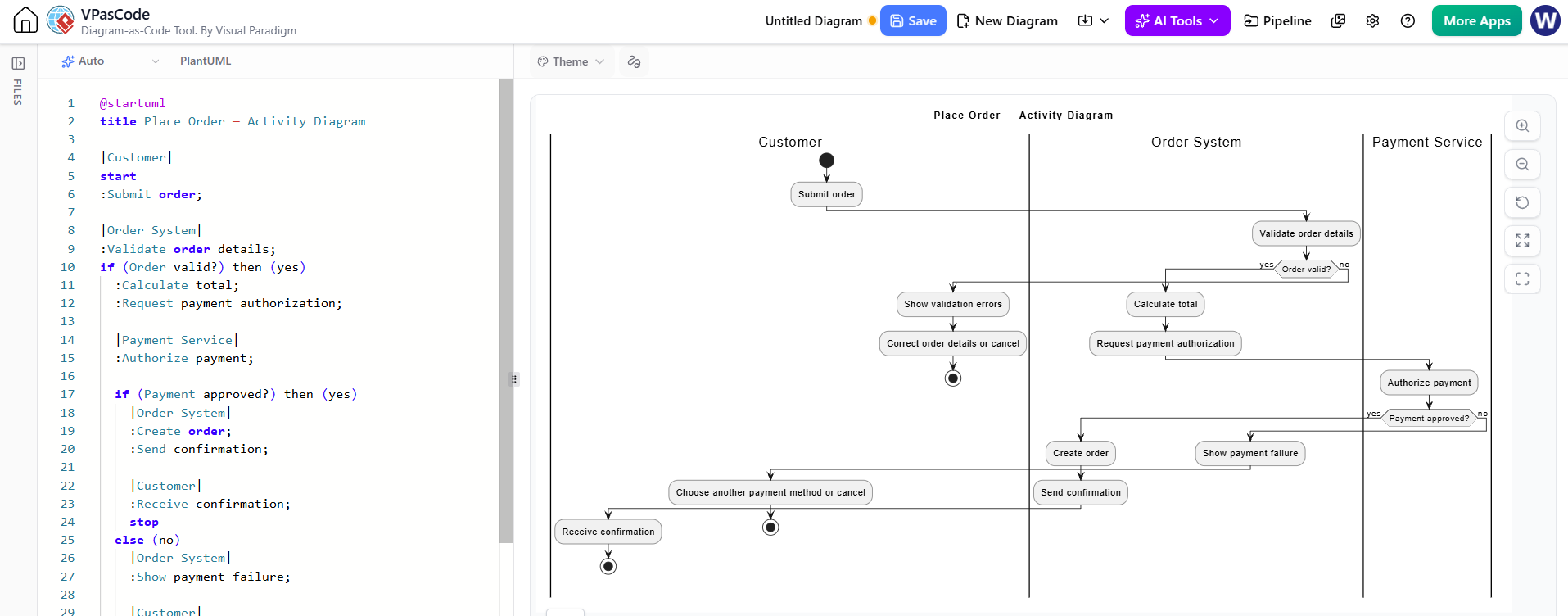
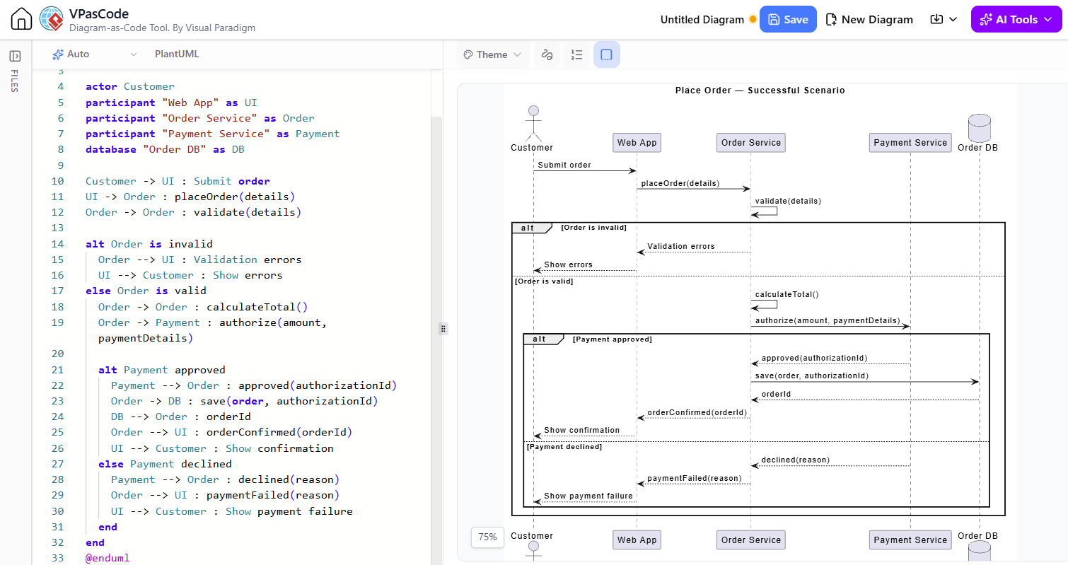
The following pair uses the same simplified use case, “Place Order.” The activity diagram emphasizes the end-to-end workflow and the decision; the sequence diagram details one valid-payment scenario.
Activity diagram: workflow view
@startuml
title Place Order — Activity Diagram

|Customer|
start
:Submit order;

|Order System|
:Validate order details;
if (Order valid?) then (yes)
  :Calculate total;
  :Request payment authorization;

  |Payment Service|
  :Authorize payment;

  if (Payment approved?) then (yes)
    |Order System|
    :Create order;
    :Send confirmation;

    |Customer|
    :Receive confirmation;
    stop
  else (no)
    |Order System|
    :Show payment failure;

    |Customer|
    :Choose another payment method or cancel;
    stop
  endif

else (no)
  :Show validation errors;

  |Customer|
  :Correct order details or cancel;
  stop
endif
@endumlSequence diagram: successful scenario
@startuml
title Place Order — Successful Scenario

actor Customer
participant "Web App" as UI
participant "Order Service" as Order
participant "Payment Service" as Payment
database "Order DB" as DB

Customer -> UI : Submit order
UI -> Order : placeOrder(details)
Order -> Order : validate(details)

alt Order is invalid
  Order --> UI : Validation errors
  UI --> Customer : Show errors
else Order is valid
  Order -> Order : calculateTotal()
  Order -> Payment : authorize(amount, paymentDetails)

  alt Payment approved
    Payment --> Order : approved(authorizationId)
    Order -> DB : save(order, authorizationId)
    DB --> Order : orderId
    Order --> UI : orderConfirmed(orderId)
    UI --> Customer : Show confirmation
  else Payment declined
    Payment --> Order : declined(reason)
    Order --> UI : paymentFailed(reason)
    UI --> Customer : Show payment failure
  end
end
@enduml
The activity diagram depicts a workflow with alternatives. The sequence diagram shows the participants and the messages exchanged along those paths. If you need only a single concrete sequence, keep one path and move other variants into separate diagrams or clearly labeled fragments.
Use-case-driven approach: when and how to apply them
A use case states a user-visible goal and describes how the system responds. It can have a main success flow and alternate or exception flows. A sequence diagram commonly represents one scenario through a use case; an activity diagram is useful for showing the flow, branching, or coordination within or across use cases.
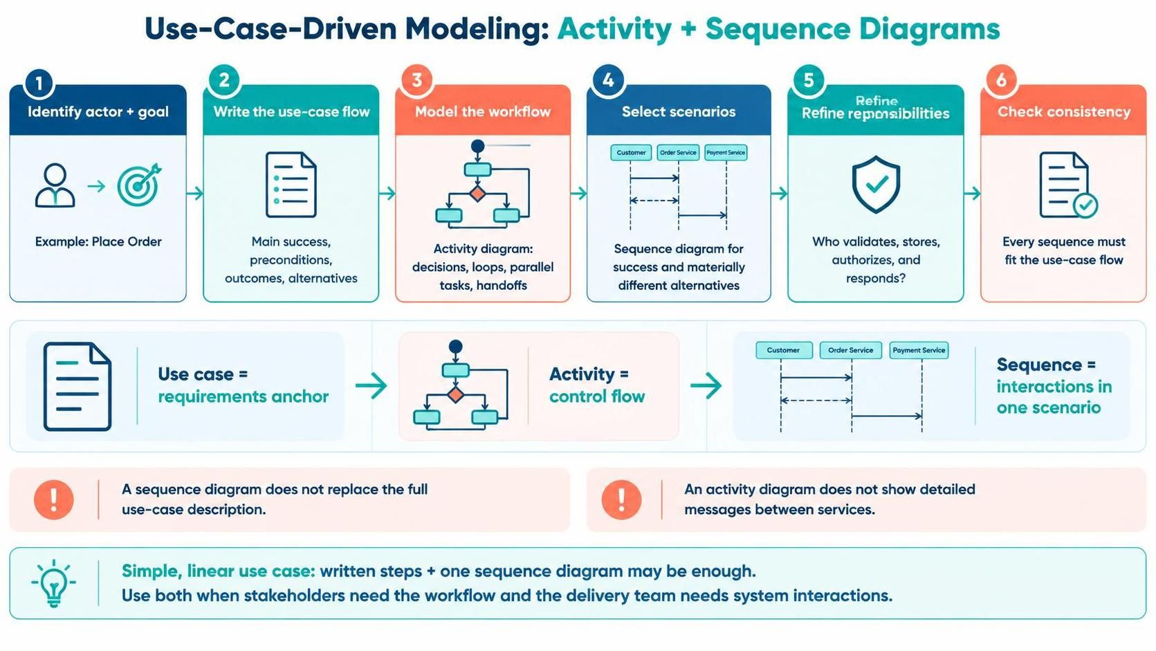
A practical workflow is:
-
Identify the actor and goal. Name the use case with a goal-oriented phrase, such as “Place Order.”
-
Write the flow of events. Record the main success path, preconditions, outcomes, and important alternatives in plain language.
-
Draw an activity diagram when the flow needs clarification. Use it to expose decisions, loops, parallel tasks, and handoffs. Keep business-level actions distinct from implementation details.
-
Choose scenarios for sequence diagrams. Create one for the main success path and add diagrams for alternate flows that involve materially different interactions—such as payment decline, timeout, or retry.
-
Refine responsibilities. Use the sequence diagram to decide which participant validates, stores, authorizes, or returns each result.
-
Check consistency. Every sequence should fit a path permitted by the activity diagram and the written use-case flow. Keep names and outcomes aligned across all three.
What differs in this approach: the use case is the requirements anchor; the activity diagram emphasizes the use case’s control flow; the sequence diagram emphasizes a selected scenario’s interactions. A sequence diagram is generally not a replacement for the full use-case description, and an activity diagram does not by itself explain the detailed messages between services.
For a simple use case with a short, linear flow, the written steps plus one sequence diagram may be enough. Use both diagrams when stakeholders need the workflow view and the delivery team also needs to understand system collaborations.
Tooling: Visual Paradigm, AI assistance, and VPasCode
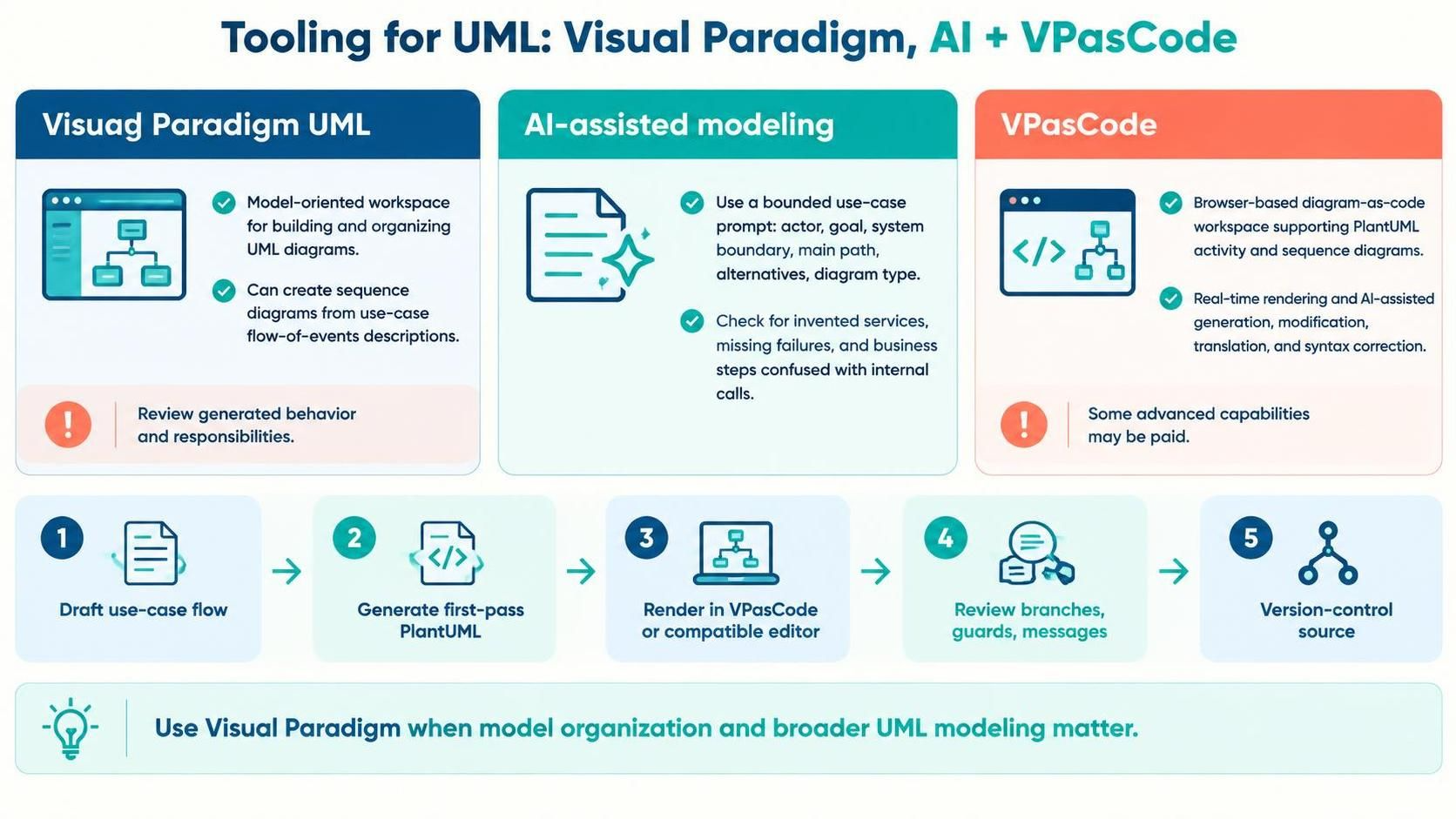
Visual Paradigm UML is useful when you want a model-oriented workspace for building and organizing UML diagrams. Visual Paradigm describes support for creating sequence diagrams from use-case flow-of-events descriptions, which can help turn a specified scenario into an interaction view. Treat that as a starting point: the generated diagram still needs to reflect the intended responsibilities and behavior.
AI-assisted modeling can speed up drafting from a use-case narrative. Give it a bounded request: name the use case, actors, system boundary, main path, key alternatives, and desired diagram type. Then check that it has not invented services, skipped failure paths, or confused business actions with internal calls. Visual Paradigm describes AI diagram generation from natural-language descriptions; generated diagrams should be reviewed against requirements.
VPasCode is a browser-based diagram-as-code workspace that supports PlantUML, including activity and sequence diagrams. It offers real-time rendering and AI features such as diagram generation, modification, translation, and syntax correction; some advanced capabilities may require a paid option. It can be useful for quickly iterating on the code examples above and keeping diagram definitions as text.
A sensible tool workflow:
-
Draft the use-case flow in plain text.
-
Ask AI for a first-pass PlantUML activity or sequence diagram.
-
Render it in VPasCode or another PlantUML-compatible editor.
-
Review the visual and semantics; fix missing branches, unclear guards, and incorrect message directions.
-
Keep the PlantUML source under version control if your team manages diagrams as text.
-
Use Visual Paradigm’s UML model workspace when you need model organization and broader UML modeling, rather than only text-to-diagram rendering.
Tips and guidelines
-
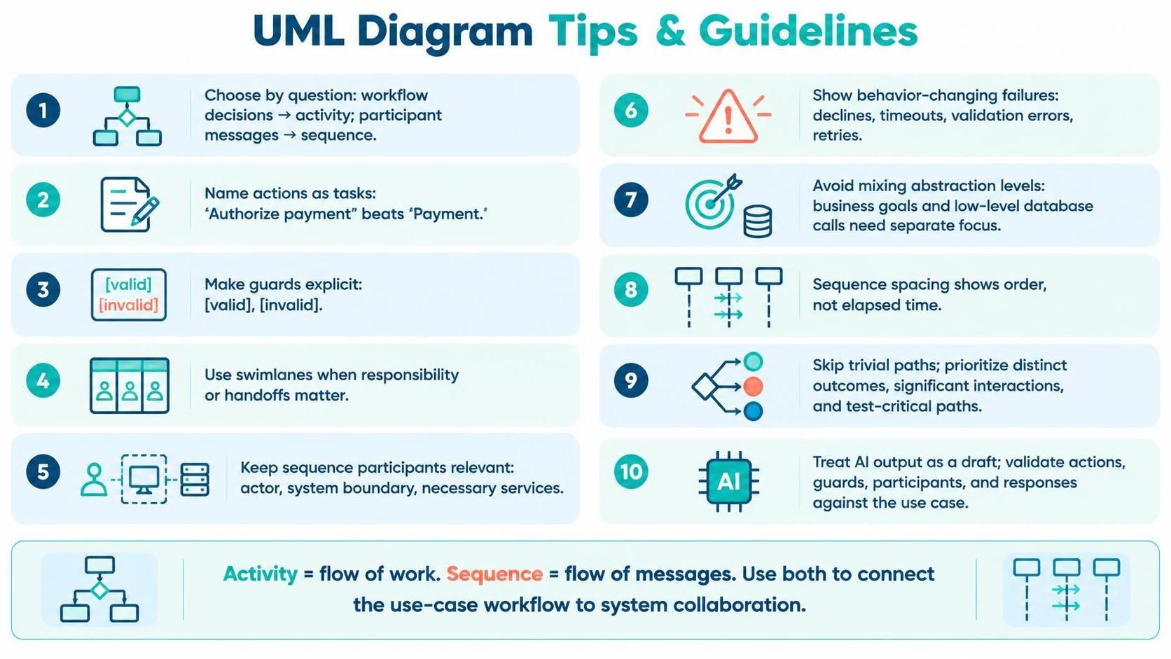
Choose by question, not by preference: workflow decisions point to activity diagrams; participant messages point to sequence diagrams.
-
Name actions as outcomes or tasks: “Authorize payment” is clearer than “Payment.”
-
Make guards explicit: label branches with conditions such as
[valid]and[invalid]. -
Use swimlanes selectively: add them when responsibility or handoff matters.
-
Keep sequence participants meaningful: show the actor, system boundary, and only the services or objects relevant to the scenario.
-
Show failures that change behavior: declines, timeouts, validation errors, and retries often deserve explicit paths.
-
Avoid mixing abstraction levels: don’t put business goals and low-level database calls in the same activity diagram unless that detail is needed.
-
Don’t imply duration from spacing: sequence diagram vertical spacing is for ordering, not a stopwatch.
-
Avoid diagramming every trivial path: prioritize paths with distinct business outcomes, significant system interactions, or test importance.
-
Treat AI output as a draft: validate every action, guard, participant, and response against the use-case specification.
Rule of thumb: use an activity diagram to communicate the flow of work, a sequence diagram to communicate the flow of messages, and both when you need to connect an understandable use-case workflow to a concrete system collaboration.