


I. Introduction
In the world of data modeling and database design, the entity-relationship diagram (ERD) plays a critical role. An ERD is a visual representation of data that helps to describe the relationships between entities and their attributes. It provides a clear and concise way to model complex systems and identify how different entities are related to each other. In this section, we will discuss the definition of an ERD and the purpose it serves in the database design process. By the end of this section, you will have a better understanding of what an ERD is and why it is an essential tool in database design.
II. Basic Concepts of Entity Relationship Diagram
In this section, we will delve into the fundamental concepts of an entity-relationship diagram (ERD). By understanding these concepts, you will be better equipped to create effective and efficient ERDs.
Entities and Attributes The first concept we will cover is entities and attributes. An entity is a person, place, thing, or concept that has data to be stored in the database. An attribute is a characteristic of the entity that provides additional information about it. In an ERD, entities are represented by rectangles, and attributes are represented by ovals.
Relationships and Cardinality The next concept we will discuss is relationships and cardinality. Relationships describe the connections between entities in the database, and cardinality refers to the number of occurrences of one entity that are related to the number of occurrences of another entity. Relationships are represented in an ERD by lines between the entities, and cardinality is indicated by symbols at the ends of the lines.
Keys and Identifiers The final concept we will cover is keys and identifiers. A key is a field or combination of fields in a table that uniquely identifies each record in the table. An identifier is a special type of key that is used to uniquely identify an entity in a database. In an ERD, keys are represented by underlined attribute names.
These basic concepts of an ERD, you will be better equipped to create effective and efficient data models that accurately represent the relationships between entities in the database.
III. Types of Entity Relationship
Diagrams Entity-relationship diagrams (ERDs) come in different types, each serving a unique purpose in the database design process. In this section, we will discuss the three main types of ERDs.
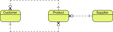
Conceptual ERD
The first type of ERD is the conceptual ERD. This type of diagram is used to model the overall structure of the database at a high level, without including details about how the database will be implemented. The focus of a conceptual ERD is on the entities and their relationships, rather than on the attributes of those entities. This type of ERD is useful for communicating the overall design of the database to stakeholders who may not be familiar with the technical details.
Conceptual data model example
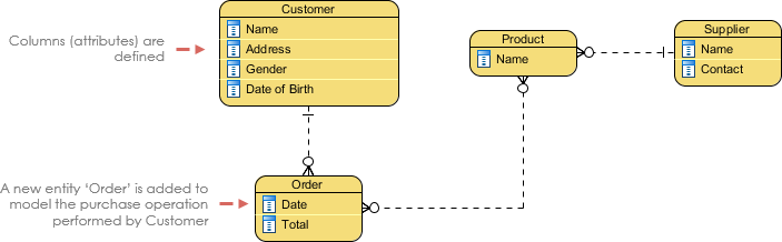
Logical ERD
The second type of ERD is the logical ERD. This type of diagram provides more detail than a conceptual ERD, but still does not include implementation details. The focus of a logical ERD is on the entities and their attributes, as well as the relationships between entities. A logical ERD is used to model the structure of the database at a level that is closer to the implementation stage, but still abstract enough to remain independent of any specific database management system.
Logical data model example
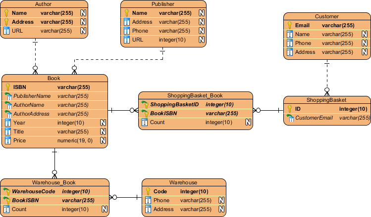
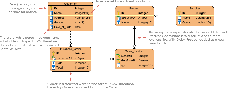
Physical ERD
The third type of ERD is the physical ERD. This type of diagram is used to model the database at a level that includes implementation details. A physical ERD includes information about the database management system being used, such as the data types of attributes and the constraints on relationships between entities. A physical ERD is used to guide the actual implementation of the database, and is closely tied to the physical schema of the database.
Choosing the appropriate type of ERD is critical to the success of the database design process. Depending on the stage of the design process, different types of ERDs may be more appropriate than others.
Physical data model example
If you are just starting out with database design, a conceptual ERD is the best place to start. This type of diagram will help you get a high-level view of the database and its relationships, without getting bogged down in the details of implementation. As you progress in the design process, a logical ERD can be useful to flesh out the details of the entities and their attributes, and to refine the relationships between them.
Once you have a solid understanding of the logical structure of the database, a physical ERD can be used to guide the actual implementation of the database. This type of diagram includes implementation details that are critical to ensuring the database is properly constructed and functions as intended.
Ultimately, the type of ERD you choose will depend on the stage of the database design process you are in, and the specific needs of your project. By understanding the different types of ERDs, you will be better equipped to choose the appropriate type for your specific needs and create effective and efficient data models.
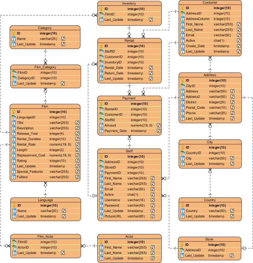
ERD example – Movie Rental System
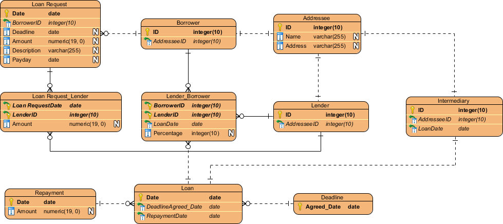
ERD example – Loan System
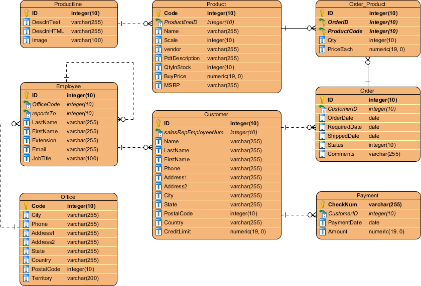
ERD example – Online Shop
IV. Steps to Create an Entity Relationship Diagram
Creating an entity relationship diagram (ERD) is a critical step in designing a database. An ERD helps to visually represent the relationships between entities and the attributes of those entities, and can serve as a blueprint for the database design. The following are the steps to create an entity relationship diagram:
- Identify the Entities – The first step in creating an ERD is to identify the entities in the database. Entities are the objects or concepts in the system that need to be stored in the database. For example, in a university system, entities could include students, courses, and instructors.
- Define the Attributes – Once the entities have been identified, the next step is to define the attributes of each entity. Attributes are the characteristics of an entity that need to be stored in the database. For example, attributes of a student entity could include their name, date of birth, and student ID.
- Determine the Relationships – After defining the entities and their attributes, the next step is to determine the relationships between the entities. Relationships describe how the entities are connected to each other. For example, in a university system, a student entity may have a relationship with a course entity indicating which courses they are enrolled in.
- Establish Cardinality and Modality – Once the relationships have been determined, it is important to establish the cardinality and modality of the relationships. Cardinality describes the number of occurrences of one entity that are associated with the number of occurrences of another entity. Modality describes whether the relationship is optional or mandatory. For example, in a student-course relationship, the cardinality could be one-to-many, indicating that a student can take many courses, and a course can have many students. The modality could be mandatory on the course side, indicating that a course must have at least one student enrolled.
- Identify the Primary Key – Finally, it is important to identify the primary key of each entity. The primary key is a unique identifier for each entity that is used to distinguish it from other entities. For example, in a student entity, the primary key could be the student ID.
By implementing these steps, you can design an entity relationship diagram that is of high-quality and effectiveness, precisely representing the relationships among the entities in your database.
V. Best Practices for Creating Entity Relationship Diagrams
Creating an entity relationship diagram (ERD) can be a complex process, but following best practices can help ensure that the diagram is effective, accurate, and easy to understand. The following are some best practices to keep in mind when creating an ERD:
- Use Clear and Concise Labels – Labels are an important part of an ERD, and it’s important to use clear and concise labels to help ensure that the diagram is easy to understand. Avoid using technical jargon or overly complex terminology that could be confusing to someone who is not familiar with the system.
- Avoid Overcrowding – It’s important to avoid overcrowding the ERD with too much information. Instead, focus on the most important entities and relationships, and use grouping and clustering to help organize the information. This can help make the diagram easier to read and understand.
- Use Consistent Notation – Consistent notation is important when creating an ERD, as it helps to ensure that the diagram is accurate and easy to understand. Use the same notation throughout the diagram, and make sure that it is consistent with the notation used in other diagrams and documentation.
- Validate and Verify – Once the ERD has been created, it’s important to validate and verify the diagram to ensure that it is accurate and reflects the system being modeled. This can involve reviewing the diagram with stakeholders, checking it against other documentation, and testing it to ensure that it works as expected.
By adhering to these best practices, you can develop a high-quality and precise entity relationship diagram that accurately portrays the relationships between entities in your system. This will not only improve the clarity and comprehensibility of the diagram but also ensure its accuracy and reliability. Overall, following these guidelines will assist in creating an effective and efficient database design that meets the needs of your stakeholders.
VI. Common Challenges in Entity Relationship Diagramming
Creating an entity relationship diagram (ERD) can be a challenging task, and there are several common issues that can arise during the process. These include:
- Incomplete or Inaccurate Information – One of the biggest challenges in ERD creation is incomplete or inaccurate information. Without complete and accurate data, it can be difficult to create an accurate and effective ERD.
- Inconsistencies in Data – Inconsistencies in data can also be a challenge when creating an ERD. This can include inconsistencies in naming conventions, data types, or data formats. These inconsistencies can make it difficult to create an accurate and effective ERD.
- Complex Relationships – ERDs can become very complex when dealing with large and complex databases. This complexity can make it challenging to accurately represent the relationships between entities and can lead to errors in the ERD.
VII. Tools for Creating Entity Relationship Diagrams
There are several tools available for creating entity relationship diagrams that can help simplify the process and overcome some of the challenges. Some of the most popular tools include:
- Microsoft Visio is a popular diagramming tool that can be used to create ERDs. It offers a range of templates and shapes that can be used to create accurate and effective ERDs.
- Visual Paradigm Online is a web-based tool that allows users to create ERDs and other types of diagrams. It offers a range of templates and shapes that can be used to create accurate and effective ERDs.
- Visual Paradigm Desktop is a popular and powerful ERD tool that offers a wide range of features and tools to assist users in creating accurate and effective ERDs. It offers a user-friendly interface, a wide range of diagramming tools and templates, and allows users to generate database schema from their ERDs. Additionally, Visual Paradigm also supports reverse engineering of ERDs from an existing database, making it easier to understand the relationships between entities. Overall, Visual Paradigm is a robust and efficient tool for creating ERDs, and its features make it an excellent choice for database design professionals.
By using these tools, and by being aware of the common challenges in ERD creation, you can create accurate and effective entity relationship diagrams that accurately represent the relationships between entities in your database.
VIII. Conclusion
Entity relationship diagramming is an essential aspect of database design and management. By accurately representing the relationships between entities in a database, an ERD can help ensure that data is organized, accurate, and easy to access. In this guide, we have explored the key concepts of ERD, including entities and attributes, relationships and cardinality, and keys and identifiers. We have also discussed the different types of ERDs, steps for creating an ERD, best practices, common challenges, and tools for creating an ERD.
It is important to note that creating an accurate and effective ERD can be a challenging task. However, by following the best practices and utilizing the available tools, users can create ERDs that accurately represent the relationships between entities in their databases.
ERDs are an essential tool for database design and management, and understanding how to create them is crucial for database professionals. By following the guidelines and best practices outlined in this guide, users can create ERDs that accurately represent the relationships between entities in their databases, leading to efficient data management and analysis.
ERD References:
- Connolly, T., & Begg, C. (2014). Database Systems: A Practical Approach to Design, Implementation, and Management (6th ed.).
- Elmasri, R., & Navathe, S. B. (2016). Fundamentals of Database Systems (7th ed.).
- Microsoft Visio. Retrieved from https://support.microsoft.com/en-us/office/create-an-entity-relationship-diagram-00fc20da-3bd1-476c-a3d3-f3086eabdd5b.
- What is Entity Relationship Diagram (ERD)?
- What is Data Modeling?
This post is also available in Deutsch, Español, فارسی, Français, English, Bahasa Indonesia, 日本語, Polski, Portuguese, Ру́сский, Việt Nam, 简体中文 and 繁體中文.