Introduction
In the world of business analysis and software design, clarity is currency. Yet, a common misconception persists: that UML Activity Diagrams are merely “extended flowcharts” and that BPMN (Business Process Model and Notation) is just a flowchart with more symbols. This view misses the fundamental distinction between these notations. They are not interchangeable; they are specialized tools designed for different modeling needs, audiences, and levels of precision.
For professionals using tools like Visual Paradigm, understanding when to use which notation is critical. A simple flowchart may remain the clearest way to explain a straightforward process to a non-technical stakeholder. However, as complexity grows—introducing parallel work, multiple organizational roles, message exchanges, or exception handling—the limitations of a basic flowchart become apparent.
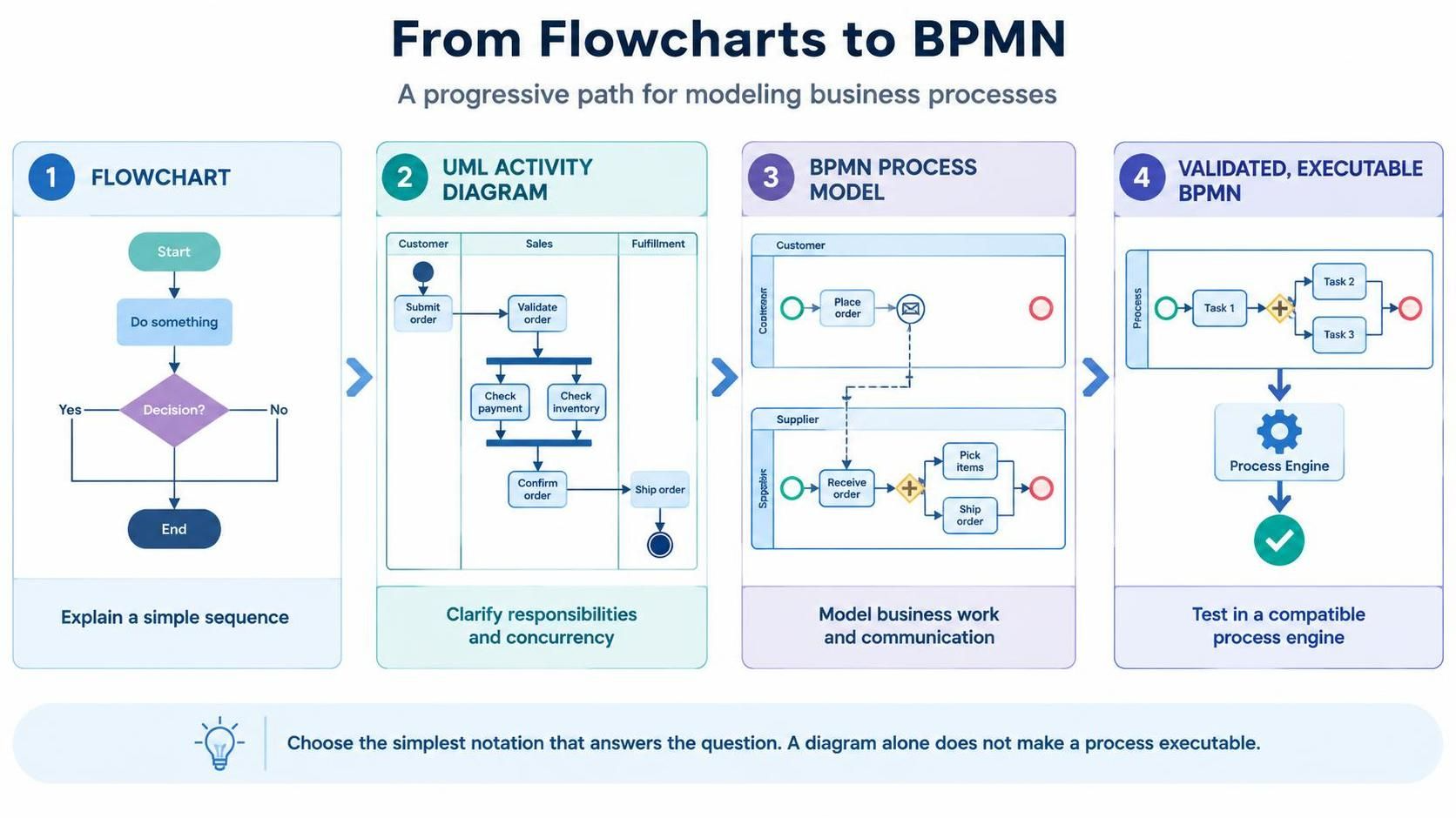
This guide outlines a practical, progressive path for mastering process modeling:
Flowchart → UML Activity Diagram → BPMN Collaboration Model → Validated, Executable BPMN Model.
By following this progression, you add precision only when necessary, ensuring that your diagrams serve their intended purpose without unnecessary complexity.
1. Understanding the Notations: Purpose and Audience
Before diving into modeling, it is essential to understand what each notation brings to the table.
| Notation | Best For | What It Adds | Typical Audience |
|---|---|---|---|
| Flowchart | Explaining short, simple sequences. | Familiar actions, decisions, and outcomes. | Almost anyone. |
| UML Activity Diagram | Modeling detailed workflows or system behavior. | Partitions (swimlanes), explicit concurrency, synchronization, and richer control flow. | Analysts, designers, developers. |
| BPMN | Modeling business processes across roles, organizations, or systems. | Standardized events, gateways, pools, message flows, timers, exceptions, and process semantics. | Business, operations, and implementation teams. |
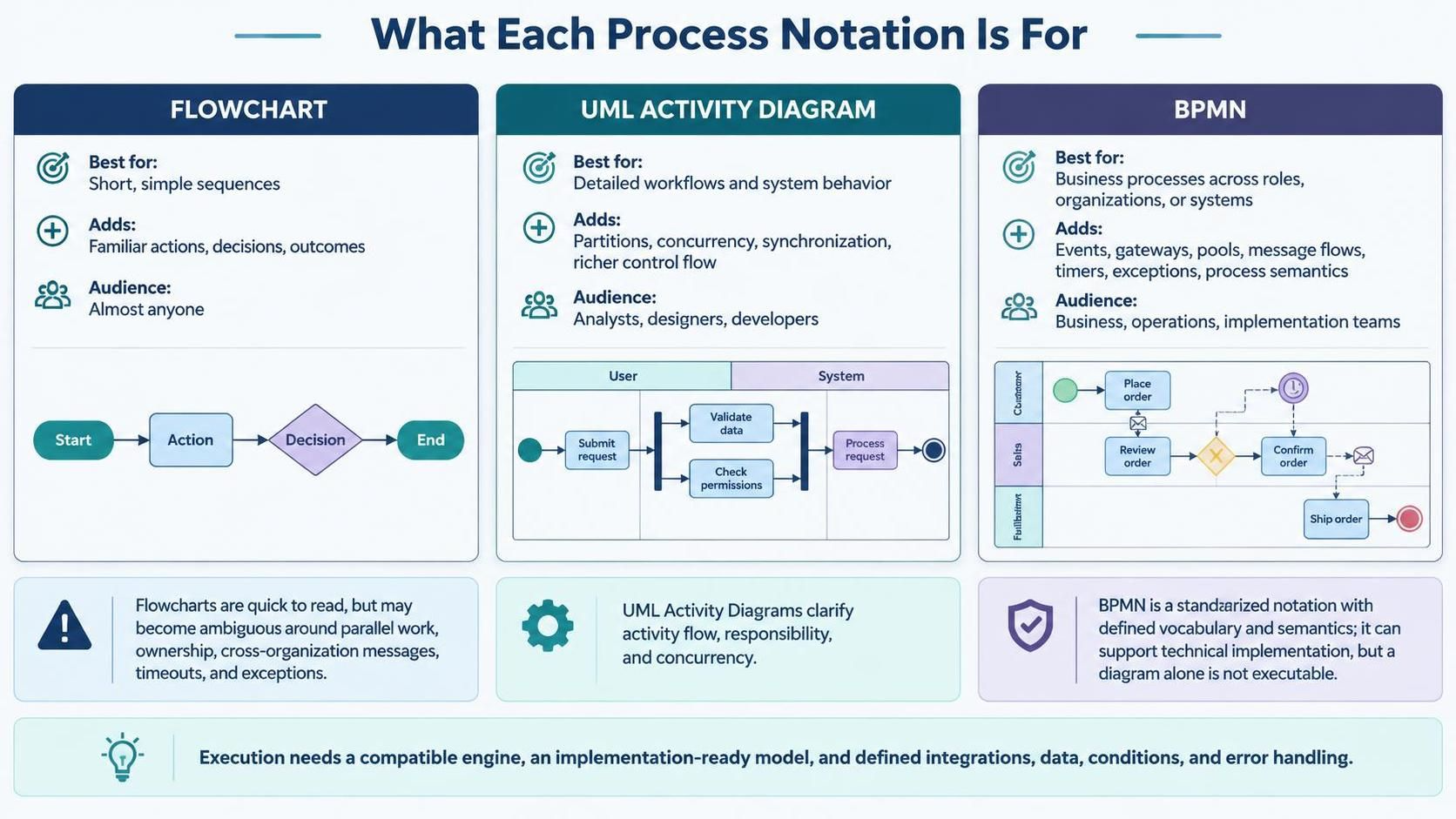
A flowchart is quick to read but often becomes ambiguous when trying to show parallel work, ownership, or external interactions. UML Activity Diagrams clarify responsibility and concurrent behavior. BPMN, an OMG standard, bridges the gap between business understanding and technical implementation, offering a precise vocabulary that supports both communication and potential execution.
Key Insight: BPMN does not automatically make a process executable. Execution requires a compatible engine, concrete service integrations, data mappings, and error handling logic. While Visual Paradigm Desktop supports BPMN modeling, always verify that your specific edition includes the features required for your goals.
2. The Learning Strategy: One Process, Multiple Layers
The most effective way to learn these notations is not by jumping between different business domains, but by modeling one familiar process repeatedly.
Consider the process of handling an online order. As you progress through the stages below, keep refining this same example. This allows you to clearly see what each notation contributes.
Before drawing any diagram, define the process in plain language:
-
Trigger: What starts the process?
-
Outcome: What counts as success?
-
Actors: Who performs each step?
-
Decisions: What conditions change the route?
-
Exceptions: What can go wrong?
-
Concurrency: Are any activities truly parallel?
-
Interactions: Are there messages, deadlines, or external parties?
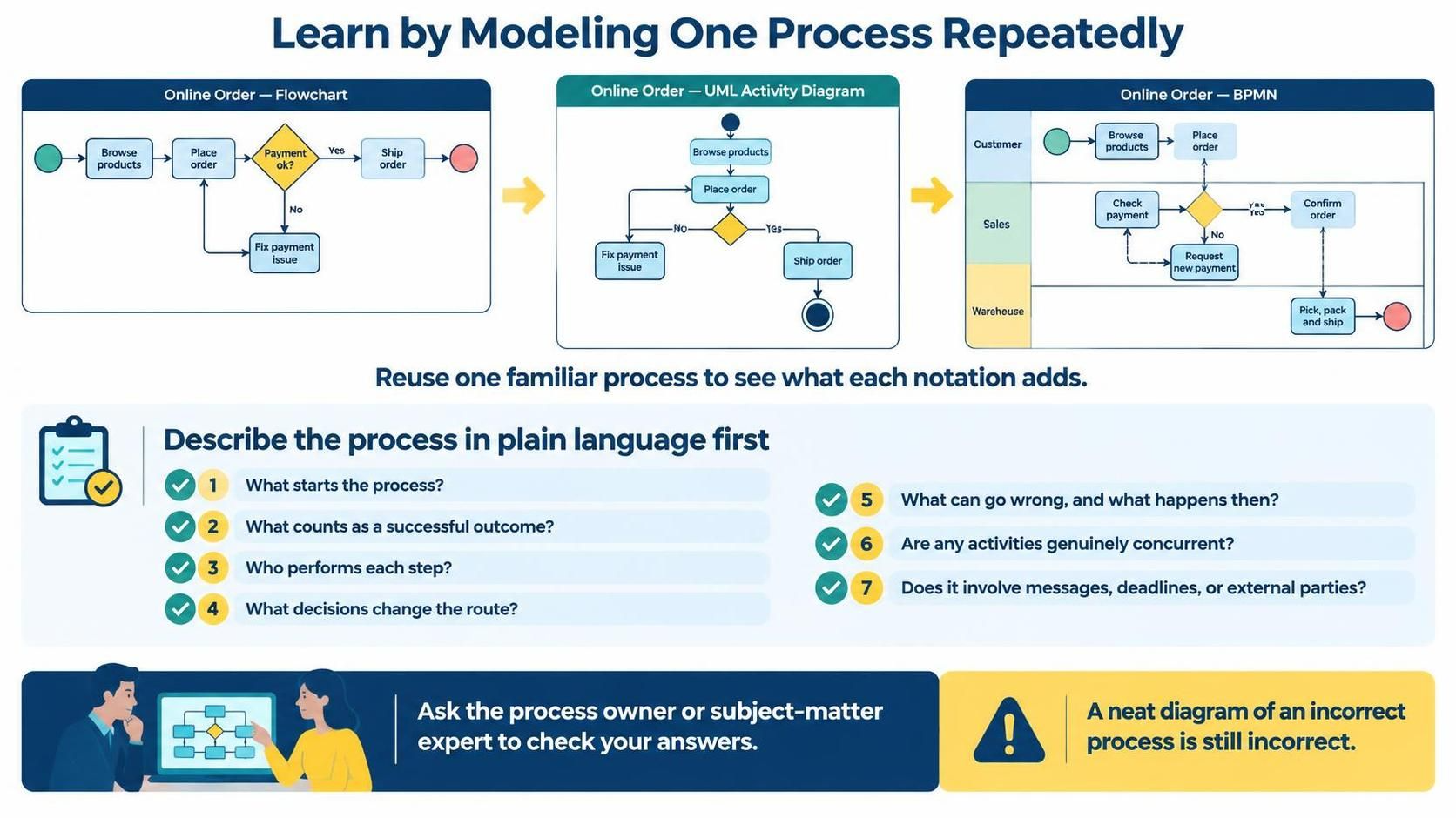
Always have a subject-matter expert validate these answers. A beautifully drawn diagram of an incorrect process is still incorrect.
3. Stage One: Clear and Simple Flowcharts
Start with the basics. Use only a few symbols: start/end, activity, decision, and arrows.
Best Practices:
-
Name activities with verb-led phrases (e.g., “Check stock,” not “Stock”).
-
Write decisions as questions (e.g., “Stock available?”).
-
Label outgoing branches clearly (e.g., “Yes” / “No”).
-
Focus on the “happy path” and one or two key alternatives.
Example 1: Basic Flowchart
Using VPasCode (Visual Paradigm’s code-based diagramming tool), you can generate a simple flowchart using PlantUML syntax. This approach is excellent for rapid iteration.
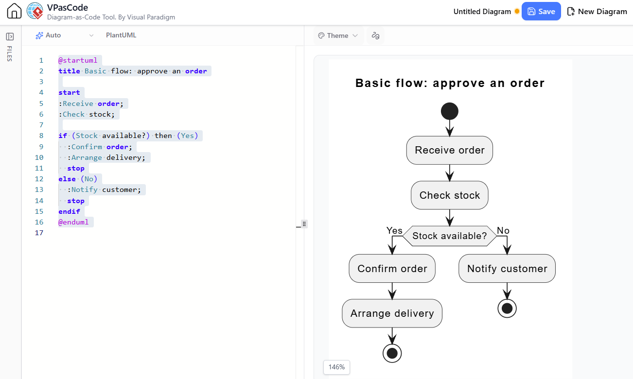
@startuml
title Basic flow: approve an order

start
:Receive order;
:Check stock;

if (Stock available?) then (Yes)
  :Confirm order;
  :Arrange delivery;
  stop
else (No)
  :Notify customer;
  stop
endif
@enduml
When to Move On: When another person can follow the diagram without narration, and decision branches have clear outcomes. If the diagram becomes crowded or fails to show who is doing the work, it’s time for UML.
4. Stage Two: UML Activity Diagrams for Precision
When a flowchart becomes ambiguous regarding ownership or parallelism, introduce UML Activity Diagram concepts. Do not add these elements arbitrarily; use them to solve specific modeling problems.
Key Concepts to Add:
-
Partitions (Swimlanes): Group activities by role, team, or system.
-
Fork and Join: Explicitly show parallel work and synchronization points.
-
Guards: Define explicit conditions on branches.
-
Object Flows: Show data moving between actions.
-
Accept Event Actions: Represent waiting for external triggers.
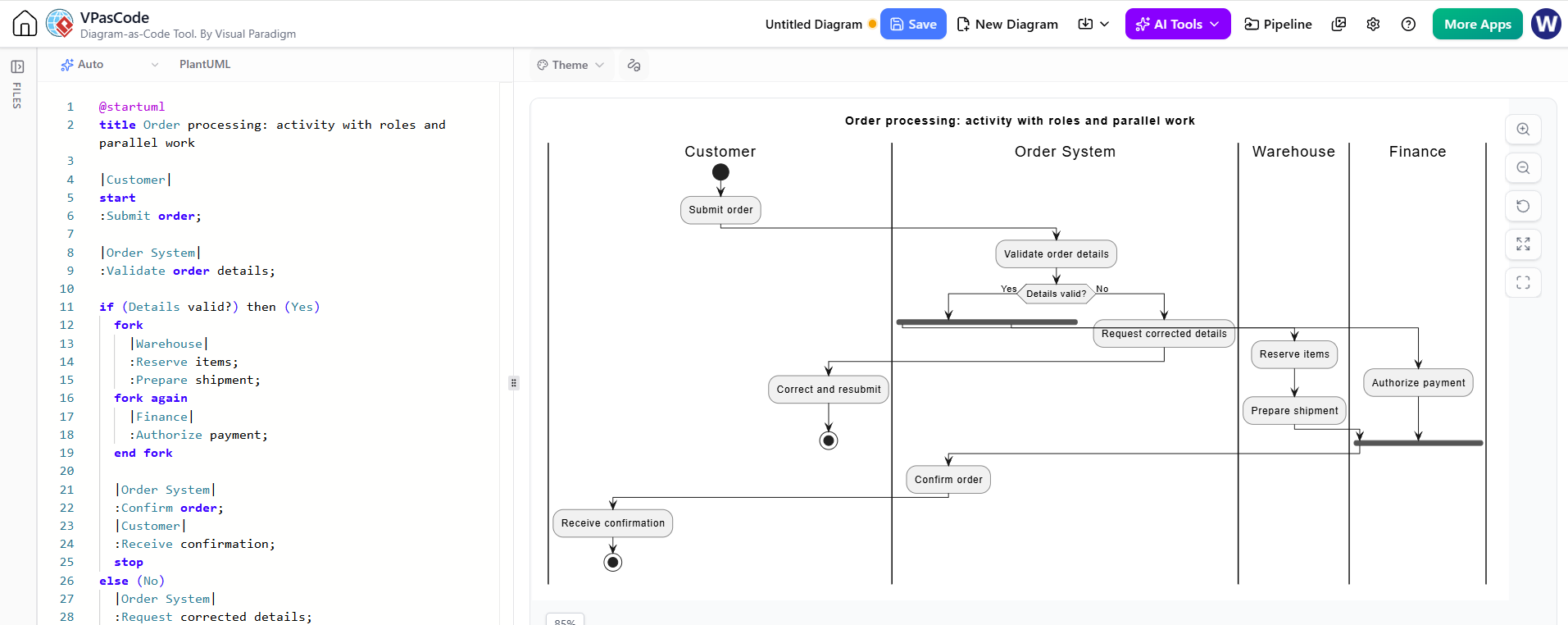
Example 2: Roles and Parallel Work
This PlantUML example demonstrates how UML Activity Diagrams clarify responsibility and concurrency.
@startuml
title Order processing: activity with roles and parallel work

|Customer|
start
:Submit order;

|Order System|
:Validate order details;

if (Details valid?) then (Yes)
  fork
    |Warehouse|
    :Reserve items;
    :Prepare shipment;
  fork again
    |Finance|
    :Authorize payment;
  end fork

  |Order System|
  :Confirm order;
  |Customer|
  :Receive confirmation;
  stop
else (No)
  |Order System|
  :Request corrected details;
  |Customer|
  :Correct and resubmit;
  stop
endif
@enduml
Critical Question: In this model, what happens if payment is declined? Is the customer waiting synchronously? If stakeholders ask these questions, you are ready for BPMN.
When to Move On: When you need clearer ownership, coordination, or system behavior than a flowchart can provide, and you can justify each added UML element.
5. Stage Three: BPMN for Business Process Clarity
BPMN is designed to be understandable to business stakeholders while remaining precise enough for technical implementation. Learn it in layers, starting with a core subset.
Core BPMN Elements
-
Events: Circles representing start, intermediate, or end states.
-
Activities: Rounded rectangles representing work.
-
Sequence Flows: Solid arrows showing order within a process.
-
Gateways:
-
Exclusive (XOR): One path chosen (e.g., Approved vs. Rejected).
-
Parallel (AND): Concurrent branches or synchronization.
-
-
Pools and Lanes: Participants and internal responsibilities.
-
Message Flows: Dashed arrows showing communication between participants.
Rule of Thumb: Use sequence flow for internal control; use message flow for external communication.
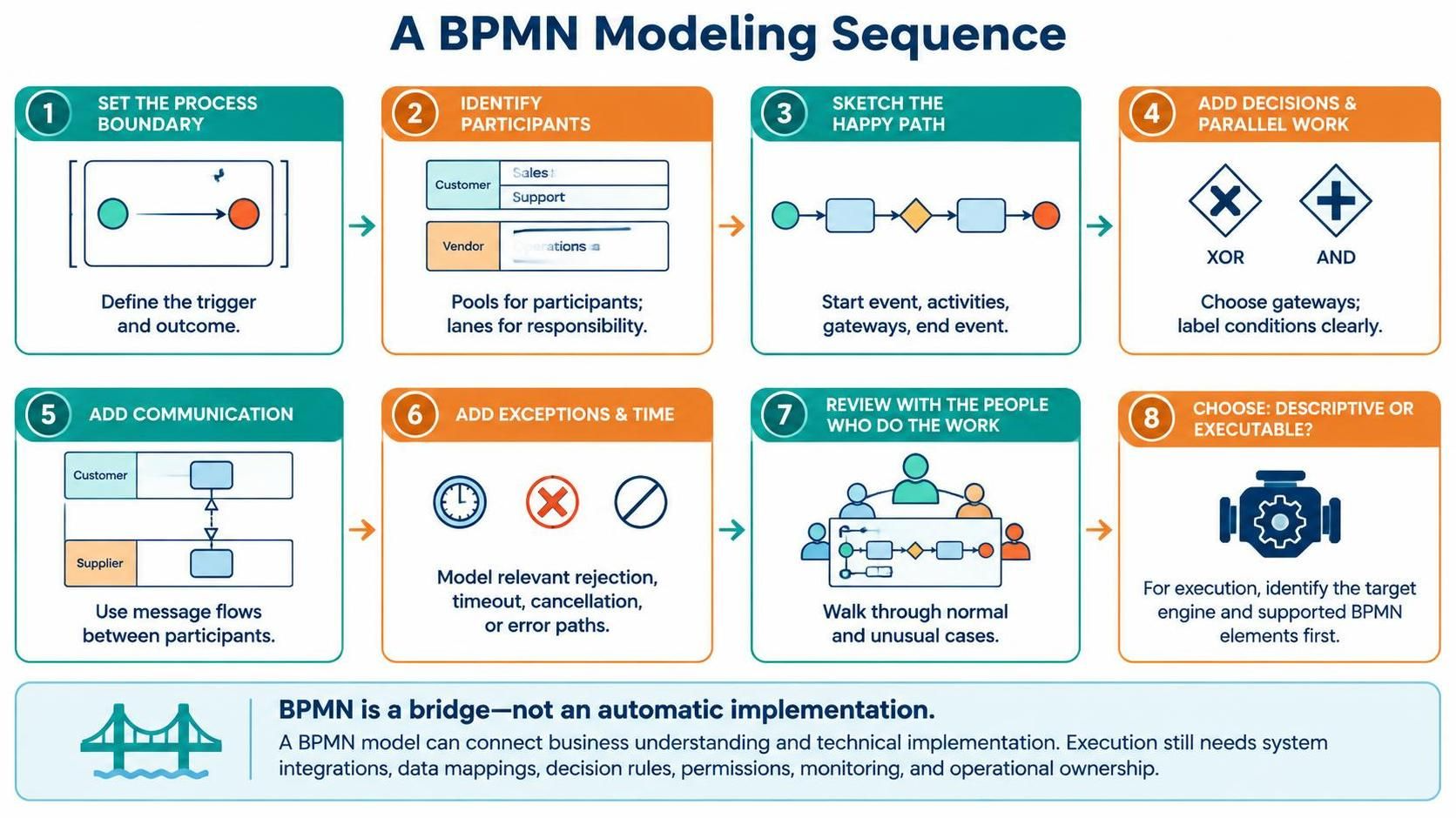
BPMN Modeling Sequence
-
Set Boundaries: Define triggers and outcomes.
-
Identify Participants: Use pools for separate entities (e.g., Customer, Warehouse, Bank).
-
Sketch Happy Path: Start event → Activities → End event.
-
Add Decisions & Parallelism: Use appropriate gateways.
-
Add Communication: Use message flows between pools.
-
Handle Exceptions: Add timeouts, errors, and cancellations.
-
Validate: Walk through real-world scenarios with process owners.
-
Define Intent: Decide if the model is descriptive or intended for execution.
As you advance, incorporate timer events, error handling, subprocesses, and data objects only as needed.
6. Stage Four: From Model to Execution
Treating execution as a separate goal is crucial. A valid BPMN diagram is not necessarily an executable program.
Pre-Execution Checklist:
-
Which BPMN engine will run this?
-
How are human tasks assigned and authenticated?
-
How are service tasks integrated (APIs, credentials, retries)?
-
How are gateway conditions evaluated?
-
What is the monitoring and auditing strategy?
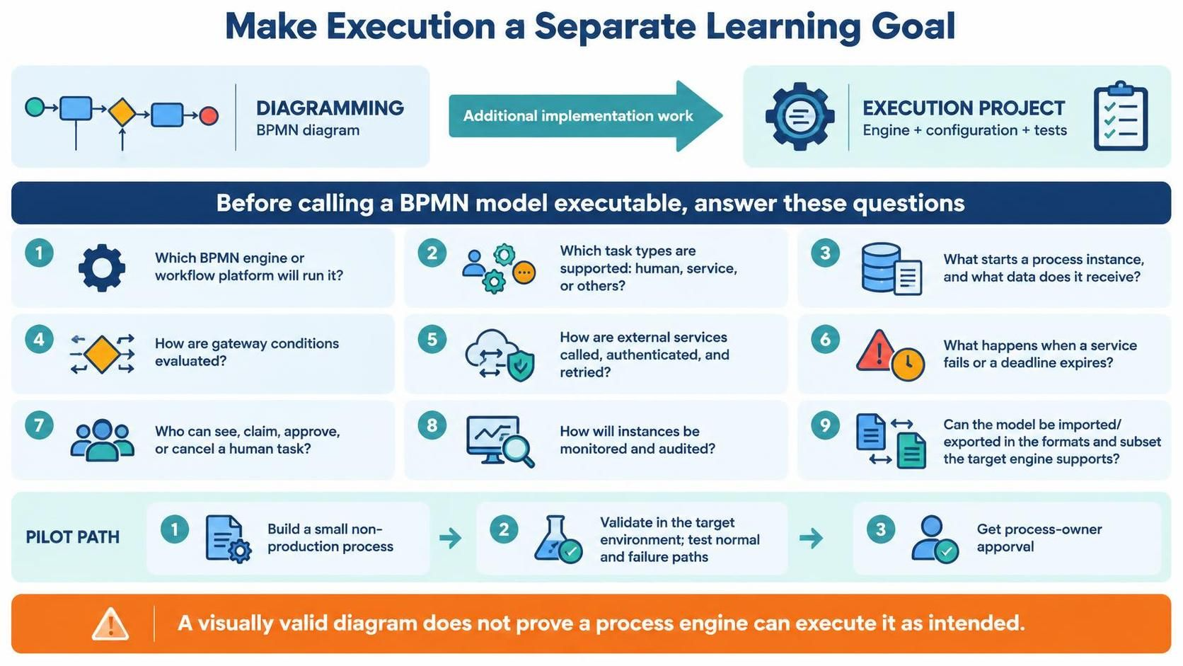
Recommendation: Start with a small, non-production pilot. Test normal and failure paths thoroughly. Ensure the target engine supports the specific BPMN elements used in your model.
7. A Beginner-Friendly Practice Plan
Use this structured approach to build skills progressively.
| Practice Stage | Build | Review Question |
|---|---|---|
| Flowchart | One short process with a decision. | Can a new reader explain the steps? |
| Activity Diagram | Same process with role partitions. | Is responsibility clearer? |
| Activity Diagram | Add genuine parallel sections. | Is synchronization correct? |
| BPMN Descriptive | Pools, lanes, events, gateways, messages. | Do business participants agree? |
| BPMN Detailed | Add timeouts, exceptions, subprocesses. | Are real-world cases covered? |
| Executable BPMN | Small process in a chosen engine. | Does it behave correctly in tests? |
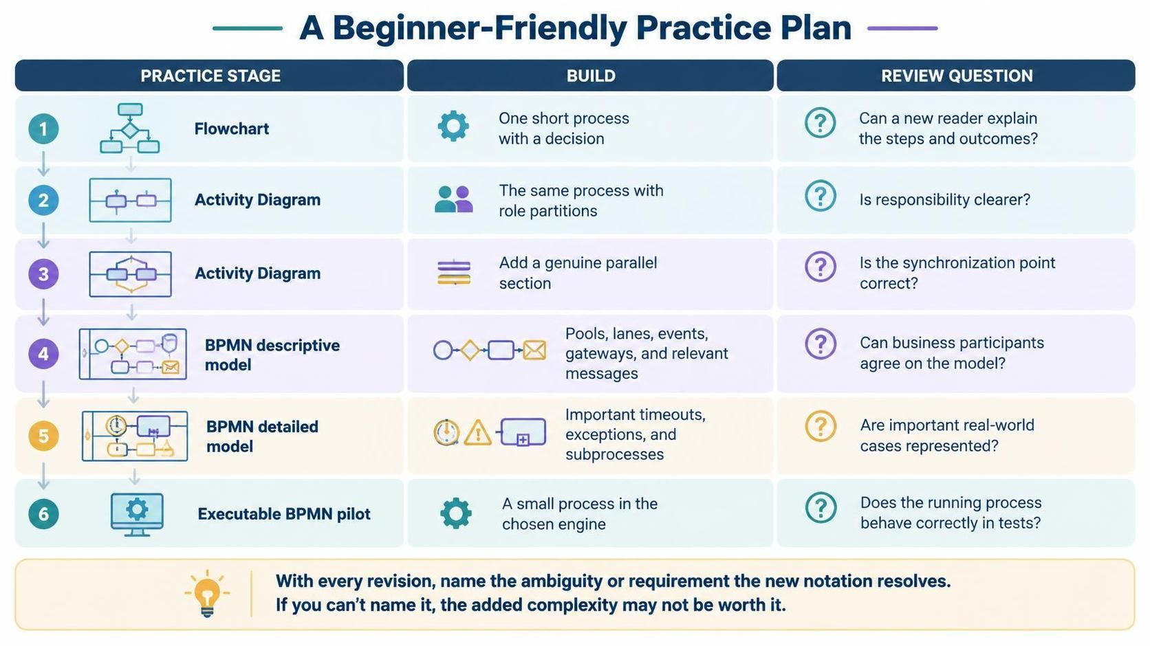
For each revision, articulate why the new notation was needed. If you cannot name the problem it solves, the complexity may be unjustified.
8. Leveraging Visual Paradigm Tools
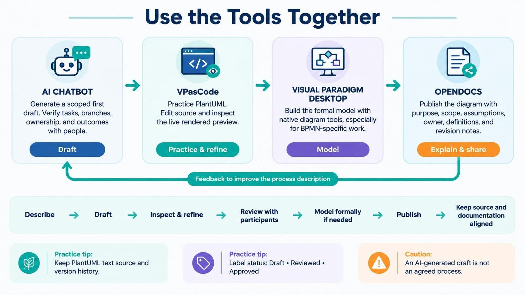
Visual Paradigm offers a suite of tools that support this progressive workflow.
-
AI Chatbot: Generate draft diagrams from text descriptions. Use case: Quick starting points. Caution: Always verify with humans.
-
VPasCode: Edit and render PlantUML code. Use case: Practicing Activity Diagrams and rapid prototyping.
-
Visual Paradigm Desktop: Formal modeling. Use case: Structured BPMN models, team collaboration, and advanced features.
-
OpenDocs: Documentation and publishing. Use case: Sharing finalized diagrams with context, assumptions, and version history.
Recommended Workflow:
Describe → Generate Draft (AI) → Refine (VPasCode) → Review with Stakeholders → Model Formally (Desktop) → Publish (OpenDocs).
9. The Role of PlantUML vs. BPMN
PlantUML is excellent for practicing flowchart and UML Activity Diagram logic via text. However, PlantUML does not generate BPMN (Visual Paradigm recently supports BPMN Generation using the custom PlantUML code to be rendered in VPasCode Tool). Rendering an Activity Diagram does not make it executable or compliant with BPMN standards.
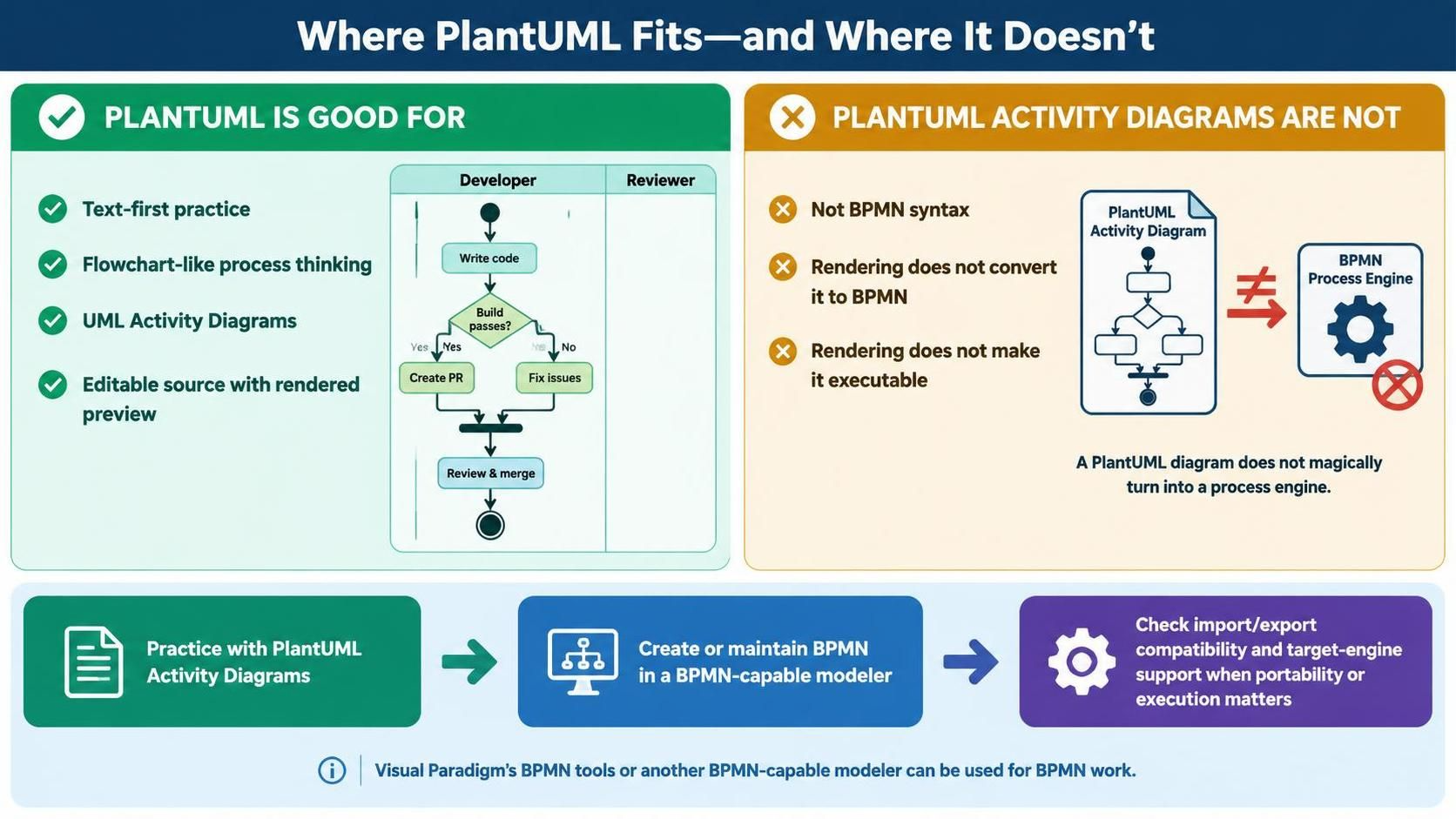
When you reach the BPMN stage, use Visual Paradigm’s native BPMN editor. If portability or execution is a goal, confirm import/export compatibility with your target engine.
10. Final Checklist for Process Diagrams
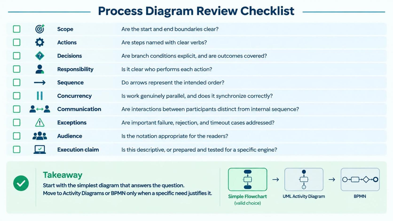
Before sharing any diagram, review it against these criteria:
-
Scope: Are start and end boundaries clear?
-
Actions: Are steps named with clear verbs?
-
Decisions: Are conditions explicit and outcomes covered?
-
Responsibility: Is it clear who performs each action?
-
Sequence: Do arrows represent the intended order?
-
Concurrency: Is parallel work and synchronization correct?
-
Communication: Are inter-participant messages distinguished from internal flow?
-
Exceptions: Are key failures and timeouts addressed?
-
Audience: Is the notation appropriate for the readers?
-
Execution Claim: Is this descriptive, or has it been tested for execution?
Conclusion
Mastering process modeling is not about memorizing every symbol in BPMN or UML. It is about selecting the right level of abstraction for the problem at hand. Start with the simplicity of a flowchart to establish shared understanding. Move to UML Activity Diagrams when you need to clarify system behavior, roles, and concurrency. Adopt BPMN when cross-organizational communication, standardized semantics, or potential automation are required.
By using tools like Visual Paradigm, VPasCode, and AI assistants strategically, you can iterate quickly, validate effectively, and produce models that are not just visually appealing, but genuinely useful. Remember: the best diagram is the simplest one that answers the current question.