


Enterprise architecture demands precision. It requires a language capable of describing complex organizational structures without ambiguity. ArchiMate serves this purpose as a standard modeling language. Understanding its anatomy is critical for anyone tasked with visualizing, analyzing, or designing the structure of an organization. This guide dissects the framework into its constituent parts, offering a practical breakdown of how these components interact to form a cohesive model.
Architecture models are not merely diagrams; they are structured representations of reality. They allow stakeholders to see the connections between strategy and execution. By mastering the components of ArchiMate, architects can ensure alignment across business, application, and technology domains. This document explores the layers, relationships, and principles that define a robust model.
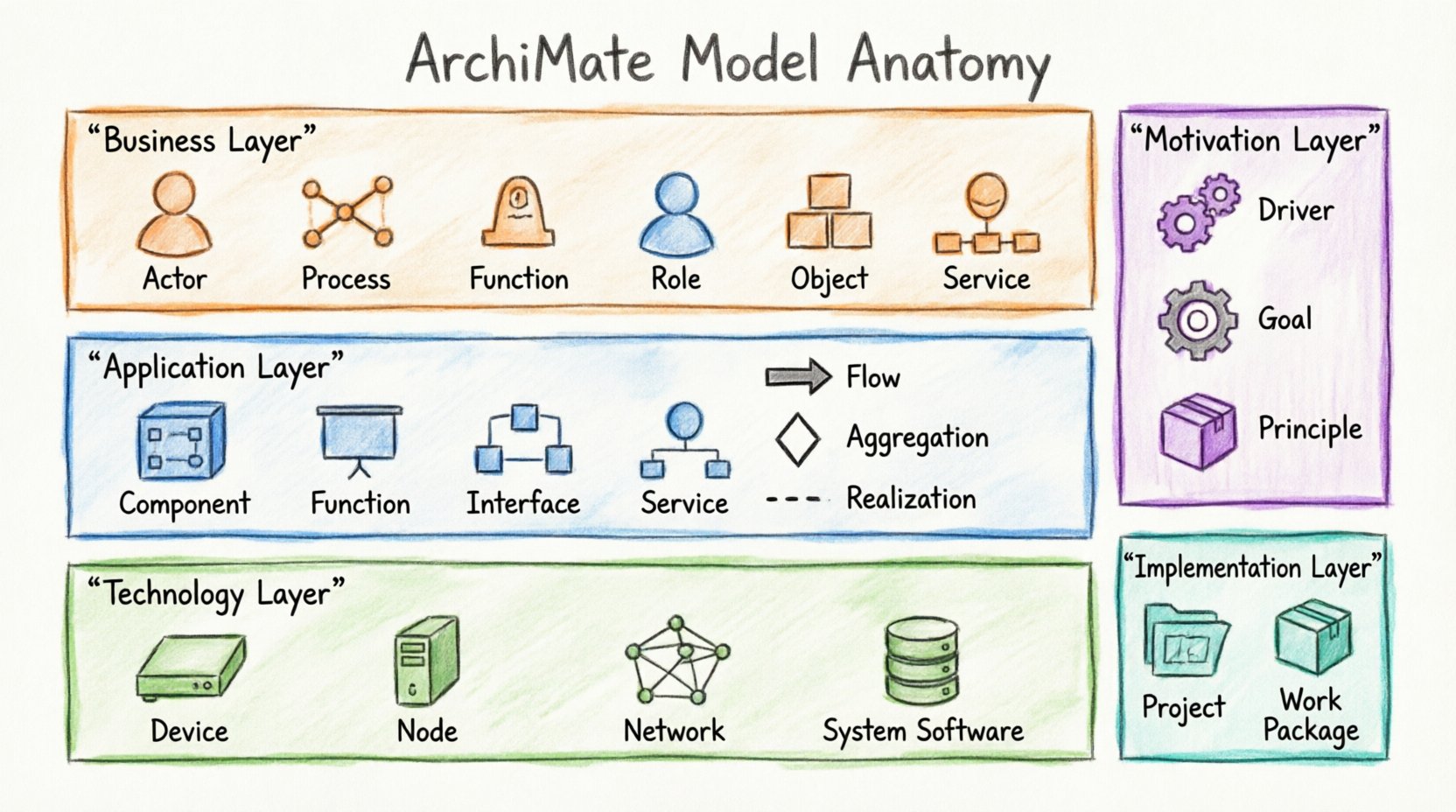
🏗️ The Three Core Layers
The foundation of any ArchiMate model rests on three primary layers. These layers provide the structural backbone for the architecture. They separate concerns while maintaining clear relationships between them. Understanding the distinction between these layers is the first step in effective modeling.
1. Business Layer
The Business Layer represents the organization from a business perspective. It focuses on value creation and the delivery of services to external and internal stakeholders. Elements in this layer describe what the organization does, not how it does it technically.
- Business Actor: Represents a role that performs business functions. Examples include a customer, a department, or an external partner.
- Business Function: A logical grouping of business behavior. This is a stable aspect of the organization, independent of who performs it.
- Business Process: A structured set of activities that achieve a specific goal. Processes are often dynamic and involve multiple actors.
- Business Role: A collection of responsibilities and authorities within a business context. Roles are assigned to Business Actors.
- Business Object: A physical or logical representation of something important to the business. Examples include invoices, products, or customer records.
- Business Service: A unit of functionality offered to a stakeholder. Services are the interface between the business and its consumers.
2. Application Layer
The Application Layer focuses on the software systems that support the business functions. It describes the application landscape and how these applications interact with data and each other. This layer bridges the gap between business requirements and technical implementation.
- Application Component: A software unit that provides functionality. It encapsulates data and behavior.
- Application Function: A behavior provided by an application. This is the logical equivalent of a business function but within the software context.
- Application Interface: A point of interaction where an application component exposes or requires functionality.
- Application Service: A unit of functionality provided by an application component to an application function or business function.
- Application Interface Point: A specific point where an interface is realized.
3. Technology Layer
The Technology Layer represents the physical and logical infrastructure. It describes the hardware, network, and system software that host the applications. This layer ensures that the computational resources are available to support the application layer.
- Device: A physical resource capable of hosting applications. Examples include servers, workstations, or mobile devices.
- System Software: Software that manages the device. This includes operating systems and database management systems.
- Network: A communication infrastructure. This includes LANs, WANs, and internet connections.
- Node: A computational resource that can host system software and applications. It is a general term for a processing unit.
- Artifact: A physical representation of a software component. Examples include source code files, executables, or configuration files.
- Infrastructure Network: A specific type of network that supports the infrastructure.
🧩 Cross-Cutting Layers
Beyond the core three layers, ArchiMate defines additional layers that provide context and direction. These layers help architects understand the “why” and the “how” of the implementation.
Motivation Layer
The Motivation Layer explains the reasons behind architectural decisions. It connects the structural elements to the drivers that influence them. This layer ensures that the architecture serves a purpose aligned with organizational goals.
- Driver: Something that motivates an action. It could be a regulation, a market trend, or a technology change.
- Goal: A desired state that the organization wants to achieve. Goals are measurable and time-bound.
- Principle: A fundamental rule or guideline. Principles constrain the behavior of the architecture.
- Requirement: A condition that must be met. Requirements are derived from goals or drivers.
- Assessment: A judgment on how well a requirement is met.
Implementation & Migration Layer
This layer describes the projects and work packages that move the organization from its current state to its target state. It is essential for planning and execution.
- Work Package: A grouping of projects and implementation activities.
- Project: A temporary endeavor undertaken to create a unique product or service.
- Assignment: The linking of an actor to a role or function.
- Gap: A difference between two states. Gaps identify the work required to close them.
Physical Layer
The Physical Layer represents the physical infrastructure. It is often used when the Technology Layer is too abstract for specific hardware descriptions.
- Physical Equipment: Specific hardware components like routers, switches, or storage arrays.
- Location: A physical place where equipment is installed.
- Communication Path: The physical medium used for communication.
🔗 Understanding Relationships
Elements alone do not form a model. Relationships define how elements interact. ArchiMate defines several relationship types that clarify the nature of the connection. Choosing the correct relationship is vital for accurate modeling.
| Relationship | Description | Example |
|---|---|---|
| Association | A generic connection between elements. | A Business Actor is associated with a Business Role. |
| Aggregation | A part-whole relationship where the part can exist independently. | A Business Process consists of Business Activities. |
| Composition | A strong part-whole relationship where the part cannot exist without the whole. | A Business Object is composed of data attributes. |
| Flow | Indicates the transfer of data or material between elements. | Data flows from a Business Object to a Business Process. |
| Access | Indicates that one element uses another without changing it. | An Application Component accesses a Database. |
| Assignment | Links an Actor to a Role or Function. | A Department is assigned to a Business Function. |
| Realization | Indicates that one element realizes another (e.g., implementation). | A Business Process realizes a Business Service. |
| Serving | Indicates that an element provides a service to another. | An Application Component serves a Business Function. |
| Triggering | Indicates a causal relationship between events. | An Event triggers a Business Process. |
| Initialization | Indicates the start of a process or activity. | A Project initializes a Work Package. |
📐 Structuring Your Model
Building a model requires discipline. A chaotic model is difficult to maintain and interpret. Follow these structural guidelines to ensure clarity and utility.
1. Define Scope Early
Before drawing elements, define the boundaries of the model. What business domain does it cover? What is the geographic scope? Which systems are included? A clear scope prevents scope creep and keeps the model focused.
2. Maintain Layer Separation
While elements in different layers relate to each other, avoid mixing them within the same view unless necessary for context. Keep the Business Layer distinct from the Technology Layer in your diagrams. This separation aids in understanding the abstraction levels.
3. Use Views Effectively
A single model can contain many views. A view is a specific representation of the model for a specific audience. Create a strategic view for executives, a functional view for business analysts, and a technical view for developers. Each view should highlight the elements relevant to that stakeholder group.
4. Consistency in Naming
Use consistent naming conventions across the model. If you use “Order Process” in the Business Layer, ensure the Application Layer reflects the same concept as “Order Management System”. Consistent terminology reduces confusion and improves searchability.
5. Validate Relationships
Every relationship should serve a purpose. Avoid drawing lines just to connect elements. Ensure that the relationship type accurately reflects the interaction. For example, use “Flow” for data movement and “Assignment” for responsibility allocation.
🛠️ Practical Application
How do you apply this anatomy in a real-world scenario? Consider a scenario where an organization needs to modernize its customer management system.
- Identify the Driver: The market requires faster response times. This is a Driver in the Motivation Layer.
- Define the Goal: Improve customer response time by 20%. This is a Goal.
- Map the Business Process: Analyze the current “Handle Customer Inquiry” process in the Business Layer.
- Identify the Application Gap: The current CRM system is slow. This is an Application Component in the Application Layer.
- Define the Target: Implement a new microservices-based architecture in the Application Layer.
- Plan the Migration: Create a Work Package to migrate from the legacy system to the new platform in the Implementation Layer.
- Assign Resources: Assign a Development Team (Business Actor) to the Migration Project.
This flow demonstrates how the layers interact. The Motivation Layer drives the Business Layer, which dictates the Application Layer requirements. The Implementation Layer manages the transition.
⚠️ Common Pitfalls
Even experienced architects make mistakes. Being aware of common errors helps you avoid them.
1. Over-Modeling
Trying to model every single detail leads to complexity that obscures the main message. Focus on the elements that drive decision-making. If an element does not influence a decision, it might not need to be in the model.
2. Ignoring the Motivation Layer
Many models focus only on structure. Without the Motivation Layer, the “why” is missing. Stakeholders may question the value of the architecture if the drivers and goals are not visible.
3. Mixing Layers inappropriately
Do not place a Database (Technology Layer) next to a Business Process (Business Layer) without a clear Application Layer in between. This breaks the abstraction and confuses the reader. Use the Application Layer to mediate between Business and Technology.
4. Inconsistent Granularity
Ensure that elements within the same view are at a similar level of detail. Do not mix high-level Business Functions with detailed Business Activities unless the diagram explicitly aims to show the hierarchy.
🚀 Future-Proofing Your Model
Architecture is dynamic. Models must evolve as the organization changes. To ensure longevity:
- Version Control: Maintain versions of your model. Track changes over time to understand the evolution of the architecture.
- Traceability: Ensure that requirements trace to goals and goals trace to drivers. This creates a clear line of sight from strategy to execution.
- Review Cycles: Schedule regular reviews of the model. Ensure it remains accurate and relevant.
- Documentation: Supplement the model with text documentation. Diagrams are powerful, but context is often found in the text.
📝 Summary of Key Components
To assist in quick reference, here is a summary of the most critical elements you will encounter.
| Layer | Key Element | Purpose |
|---|---|---|
| Business | Business Process | Describes activities to achieve a goal. |
| Business | Business Object | Represents data relevant to the business. |
| Application | Application Component | Software unit providing functionality. |
| Application | Application Interface | Point of interaction for services. |
| Technology | Node | Computational resource for hosting. |
| Technology | Device | Physical hardware resource. |
| Motivation | Driver | Motivates architectural change. |
| Motivation | Goal | Desired state of the organization. |
| Implementation | Project | Temporary effort to deliver change. |
By adhering to these structural principles and understanding the relationships between components, you can build models that are clear, maintainable, and valuable. The Anatomy of an ArchiMate Model is not just about drawing shapes; it is about communicating complex organizational dynamics with precision. Use this breakdown as a foundation for your architectural work.
This post is also available in Deutsch, Español, فارسی, Français, English, Bahasa Indonesia, 日本語, Polski, Portuguese, Ру́сский, Việt Nam, 简体中文 and 繁體中文.