


Enterprise architecture often feels distant from the daily realities of infrastructure operations. Yet, the gap between business strategy and physical hardware is bridged by a robust modeling framework. ArchiMate provides a standardized language for this purpose, specifically within the Technology Layer. For infrastructure teams, understanding how to model servers, networks, and storage is not just about documentation; it is about clarity in complex environments.
This guide explores the practical application of ArchiMate concepts for infrastructure professionals. We will examine the core elements of the technology layer, how they relate to applications and business functions, and the specific challenges involved in modeling modern hybrid environments. The goal is to create a clear, maintainable model that supports decision-making without introducing unnecessary complexity.
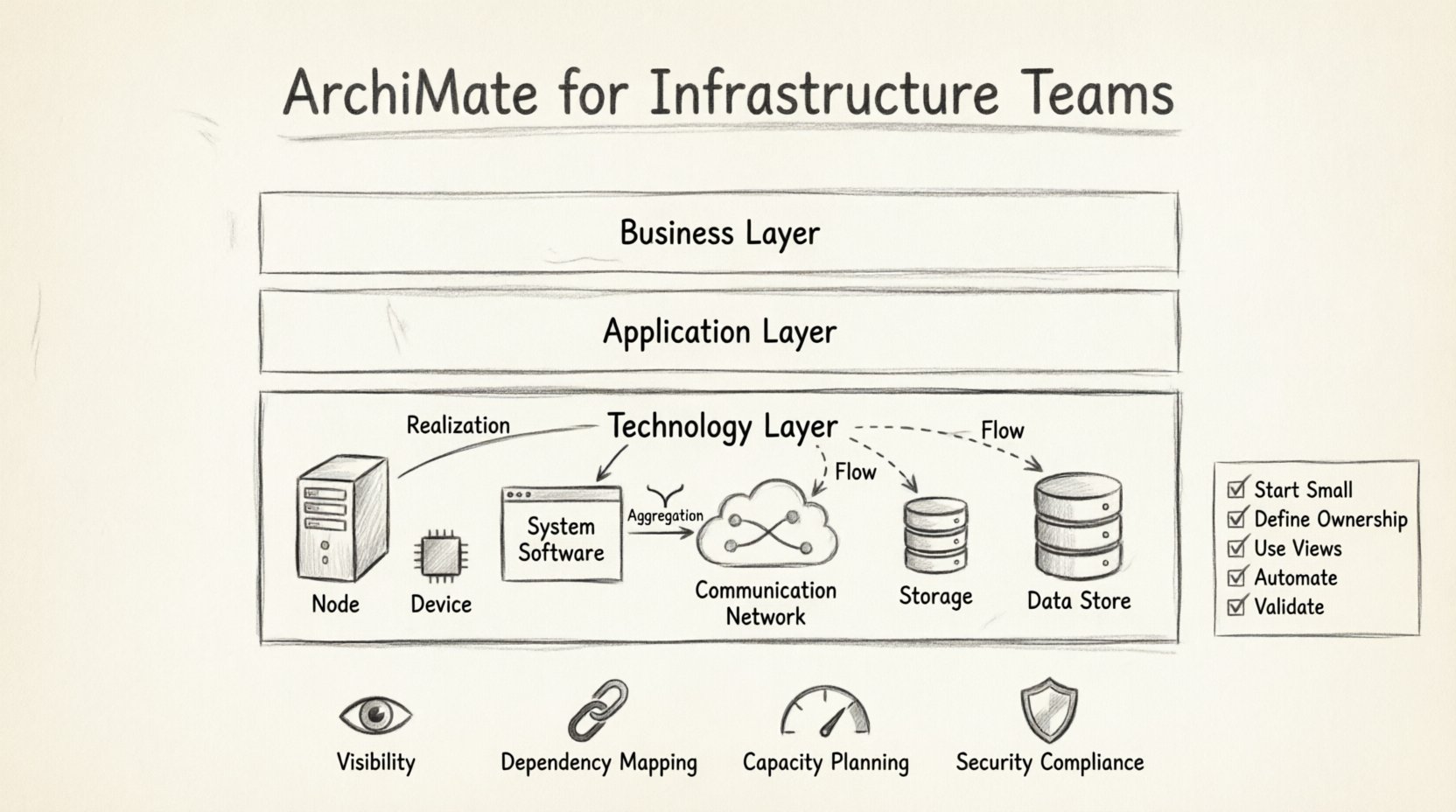
🔍 Understanding the Technology Layer Context
The Technology Layer in ArchiMate represents the physical and logical infrastructure that supports the execution of business processes and applications. It is the foundation upon which the Application Layer sits. While business stakeholders focus on value streams and capabilities, infrastructure teams focus on nodes, devices, and connections.
Modeling this layer requires precision. Ambiguity here leads to deployment errors, security gaps, and inefficient resource allocation. The following points highlight why this layer matters:
- Visibility: It creates a single source of truth for physical assets.
- Dependency Mapping: It shows which application services rely on specific network paths or storage systems.
- Capacity Planning: It helps identify bottlenecks where infrastructure cannot support business growth.
- Security Compliance: It visualizes data flows and physical boundaries for audit purposes.
When infrastructure teams adopt this framework, they stop viewing themselves as isolated support units and start viewing their assets as strategic enablers.
🧱 Core Elements of the Technology Layer
The Technology Layer is composed of specific object types that represent hardware and software components. Understanding the distinction between these elements is crucial for accurate modeling. Below is a breakdown of the key objects.
1. Node
A Node represents a computational, physical, or logical device. It is the most fundamental element. There are two primary subtypes:
- Infrastructure Node: Represents a physical device such as a server, router, or switch. It is often associated with a specific physical location.
- Software Node: Represents a software environment, such as a container runtime, a virtual machine, or a database instance. This is critical for cloud modeling.
2. Device
A Device is a physical artifact that can be attached to an Infrastructure Node. Think of a network card, a hard drive, or a USB port. While an Infrastructure Node might be a server, the Device represents the specific components within it. This distinction allows for granular inventory management.
3. System Software
This element represents the software that runs on a node. It includes operating systems, middleware, and database management systems. When modeling a migration from one OS to another, the System Software element is the primary focus of change.
4. Communication Network
This element represents the infrastructure that enables communication between nodes. It includes LANs, WANs, and the internet. Modeling this layer helps visualize network topology, latency zones, and connectivity requirements.
5. Storage
Storage represents the physical or logical location where data is stored. This could be a SAN, a NAS, or a cloud storage bucket. It is distinct from the System Software that manages the data.
6. Data Store
A Data Store is a logical representation of data persistence. It is often used to show where specific data objects reside, regardless of the underlying physical storage hardware.
Understanding these definitions prevents the common pitfall of mixing logical concepts with physical hardware. Consistency in naming and categorizing these elements ensures the model remains useful over time.
🔗 Key Relationships and Connections
Elements alone do not provide value. The relationships between them define the architecture. In the Technology Layer, relationships describe how components interact, depend on one another, or contain one another.
1. Realization
The Realization relationship indicates that one element provides the implementation for another. For example, a System Software element realizes a Service from the Application Layer. A Device realizes the functionality of a Node.
2. Aggregation
Aggregation describes a whole-part relationship. An Infrastructure Node aggregates multiple Devices. A Communication Network aggregates multiple Nodes. This helps in calculating capacity and understanding the scope of a failure.
3. Association
An Association is a general relationship that connects two elements. It is often used when the relationship is too complex to define specifically as aggregation or realization. For example, a logical link between two storage systems.
4. Flow
The Flow relationship represents the movement of data or objects. In the Technology Layer, this is vital for understanding data traffic. A Data Store flows to a System Software element during a read operation. This helps in performance modeling.
| Relationship Type | Description | Example |
|---|---|---|
| Realization | Implementation | Server realizes Operating System |
| Aggregation | Whole-Part | Network aggregates Switches |
| Flow | Data Movement | Data flows from Database to App |
| Access | Usage | App accesses Storage |
🌐 Modeling Modern Infrastructure Scenarios
Infrastructure is rarely static. Teams frequently face scenarios involving cloud adoption, disaster recovery planning, or network segmentation. ArchiMate provides the vocabulary to model these changes effectively.
1. Cloud Migration
When moving from on-premises hardware to cloud services, the Technology Layer must reflect both the legacy and the new state. Model the existing Infrastructure Nodes and the new Software Nodes representing cloud instances. Use the Realization relationship to show how the cloud environment replaces the physical hardware.
Key considerations include:
- Identifying which System Software can be lifted and shifted versus refactored.
- Mapping network connectivity changes between on-prem and cloud.
- Defining data storage requirements in the new environment.
2. Disaster Recovery (DR)
DR planning requires understanding dependencies. If a primary site fails, what components must be available in the secondary site? Model the primary and secondary sites as separate Infrastructure Nodes. Use Aggregation to group the servers in each site. Use Flow to show data replication paths.
This visualization helps answer critical questions:
- What is the Recovery Time Objective (RTO) for each node?
- Are the storage systems replicated synchronously or asynchronously?
- Does the network topology support failover?
3. Network Segmentation
Security often requires segmenting networks. Model these segments as distinct Communication Network elements. Connect them via defined Ports or gateways. This allows security teams to verify that sensitive data stores are only accessible through specific paths.
🤝 Integration with Other Layers
The Technology Layer does not exist in isolation. It connects to the Application Layer and the Business Layer. These connections are where the true value of the architecture emerges.
1. Application Layer Interaction
Applications run on technology. The Application Service is realized by Application Components, which are deployed onto System Software on Infrastructure Nodes. This chain of realization allows teams to trace a business requirement down to the physical hardware.
For example:
- Business Process: Process Order.
- Application Service: Order Management.
- System Software: Java Runtime Environment.
- Infrastructure Node: Production Server 01.
Mapping this chain helps in capacity planning. If the Business Process volume increases, the team can calculate the required increase in Infrastructure Nodes.
2. Business Layer Interaction
The Business Function is enabled by the Business Process, which is supported by the Application Service. Ultimately, the Infrastructure Node supports the entire chain. While this is often modeled at a higher level, infrastructure teams benefit from understanding the business drivers behind their asset management.
Understanding the business context prevents over-provisioning. If a specific Business Function is being phased out, the associated Infrastructure Nodes can be decommissioned, reducing costs.
⚠️ Common Challenges and Pitfalls
Implementing this framework in an infrastructure team environment comes with hurdles. Awareness of these challenges helps in avoiding common errors.
1. Abstraction Level Confusion
A frequent issue is mixing logical and physical models. A Data Store is logical; a Storage element is physical. Mixing them creates ambiguity. For instance, modeling a “Database” as a physical Storage element is incorrect if it refers to the software service. Keep the logical data model separate from the physical storage model.
2. Naming Conventions
Consistency is key. If one engineer names a server “Server-01” and another names it “Prod-DB-01”, the model becomes unreadable. Establish a naming standard based on function, location, and type before modeling begins.
3. Tooling Neutrality
While modeling frameworks exist, the software used to visualize them should not dictate the model. Avoid features in specific tools that force a non-standard representation of ArchiMate elements. Stick to the standard definitions to ensure the model remains portable and understandable.
4. Maintenance Overhead
An architecture model that is not updated becomes obsolete quickly. Infrastructure changes frequently. Teams must integrate model updates into their change management processes. If a server is replaced, the model must be updated immediately. Otherwise, the model loses trust.
✅ Best Practices for Implementation
To ensure long-term success, infrastructure teams should adopt specific practices when modeling.
- Start Small: Do not attempt to model the entire data center at once. Start with a critical business service and work backward to the infrastructure.
- Define Ownership: Assign ownership of specific parts of the model to specific teams. Network teams own the Communication Network elements; Server teams own the Infrastructure Nodes.
- Use Views: Create different views for different audiences. Security teams need a view focused on Data Stores and Ports. Operations teams need a view focused on Nodes and Devices.
- Automate Where Possible: Use scripts to import data from inventory systems into the model. Manual entry leads to errors and staleness.
- Validate Regularly: Conduct quarterly reviews to ensure the model matches the physical reality. Walk the floor and verify the nodes.
📈 Measuring Success
How do you know the modeling effort was worthwhile? Look for these indicators:
- Reduced Downtime: Better dependency mapping leads to fewer surprises during maintenance.
- Faster Incident Resolution: Engineers can quickly identify the physical component causing a service failure.
- Cost Optimization: Accurate capacity planning prevents buying unnecessary hardware.
- Clearer Communication: Stakeholders understand the technical constraints better.
🛠️ Practical Modeling Steps
Follow this sequence to build a reliable Technology Layer model.
- Identify Business Drivers: What services are critical to the business?
- Define Application Services: What software capabilities support these services?
- Map to System Software: What operating systems or runtimes are required?
- Deploy to Nodes: Which physical or virtual servers will host the software?
- Connect via Network: How do these nodes communicate?
- Store Data: Where does the data reside?
- Review Relationships: Ensure all dependencies are correctly modeled using Realization, Aggregation, and Flow.
🚀 Future Considerations
Infrastructure is evolving rapidly. Technologies like Kubernetes, Serverless, and Edge Computing introduce new elements that may not fit perfectly into traditional models. The framework is flexible enough to accommodate these changes.
- Containerization: Treat containers as Software Nodes or System Software depending on the level of detail required.
- Serverless: Model serverless functions as Application Services without explicit Infrastructure Nodes in the immediate model, focusing on the provider instead.
- Edge Computing: Model edge devices as Devices connected to a central Communication Network.
By keeping the core definitions consistent, teams can adapt the model as technology shifts without losing the structural integrity of the architecture.
🎯 Summary of Key Takeaways
- The Technology Layer is the foundation for physical and logical infrastructure.
- Clear definitions of Nodes, Devices, and Software prevent modeling errors.
- Relationships like Realization and Flow explain how components interact.
- Integration with the Application and Business layers provides strategic value.
- Maintenance and consistency are critical for the model to remain useful.
Adopting ArchiMate for infrastructure teams is a journey toward clarity. It transforms a chaotic collection of hardware into a structured, understandable asset. This structure supports better decisions, smoother operations, and a stronger alignment between technology and business goals. The effort invested in modeling pays dividends in operational resilience and strategic agility.
This post is also available in Deutsch, Español, فارسی, Français, English, Bahasa Indonesia, 日本語, Polski, Portuguese, Ру́сский, Việt Nam, 简体中文 and 繁體中文.