


What is use case analysis?
Use case diagrams are mainly used to describe roles and the connections between roles and use cases. Explain who will use the system and what they can do with it.
A use case diagram contains multiple model elements, such as systems, participants, and use cases, and shows various relationships between these elements, such as generalization, association, and dependency.
It shows a functional model diagram of the system that an external user can observe. Use cases help the development team understand the functional requirements of the system in a visual way.
The Elements of Use Case Diagram
The use case diagram contains 6 elements, namely
- Actor
- Use Cases
- Association
- Include relationships
- Extended relationships (Extend)
- Generalization relation
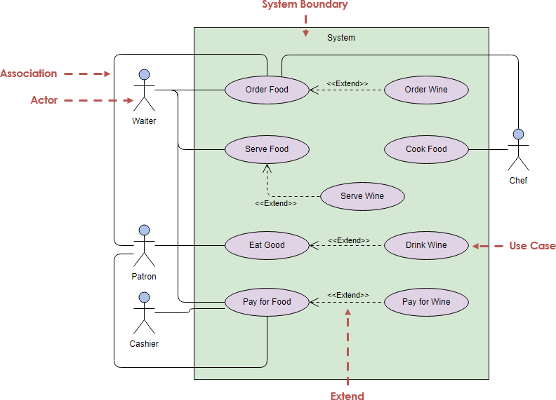
Alternatively, you can place system boundaries in the use case diagram to indicate the scope of the system.
Actor
What are the roles that use this system? Different roles use different system functions, which are represented by villains in the use case diagram.
- An external entity
- Participate in the use case execution process
- Actors are represented by the roles they play in participating in a use case
- Each actor can participate in one or more use cases
Types of Actor
- Users of the system- Real people, users, are the most common actors that exist in almost every system, and they should be named according to roles
Other systems that interact with the system being built - External program — Example, when the customer has not returned the car by the time of return, the system will remind the customer service representative to call the customer, and time or external system becomes a player in the system
- Others include hardware devices, external services, and external databases
How to find system participants?
- Who will use the main functions of the system
- Who will need the system’s support to do its job
- Who will need to maintain and manage the system
- Which hardware devices the system needs to handle
- What system is interacting with this system
Starter and supporter
- Who or what system is interested in the results produced by this system
- The initiator is the primary service object of the use case
The other is the participant who plays the role of supporter
Relationship between use cases
Association relationship (it represents the relationship between participants and use cases. In UML, it is often represented by a straight line or a line with an arrow pointing to the information receiver)
Structuring Use Cases with Relationships
Extend / extension relationship (it means that new behaviors are added to existing use cases under certain conditions. The obtained new use cases are called extended use cases, and the original use cases are called basic use cases, which is equivalent to providing an additional function for the basic use cases. It is represented by dotted lines with arrows in UML, and the arrows point to the basic use cases)
Included relationship (it means that the behavior of other use cases can be simply included, and the use case behavior contained in it can be regarded as a part of its own behavior. It is often represented by dotted lines with arrows in UML, and the arrows point to the included use cases)
Generalization relationship (refers to that a parent use case can be specialized to form multiple child use cases, and the relationship between parent use cases and child use cases is the generalization relationship. In UML, it is represented by a solid line of a hollow triangular arrow, and the arrow points to the parent use case)
Use Case Examples
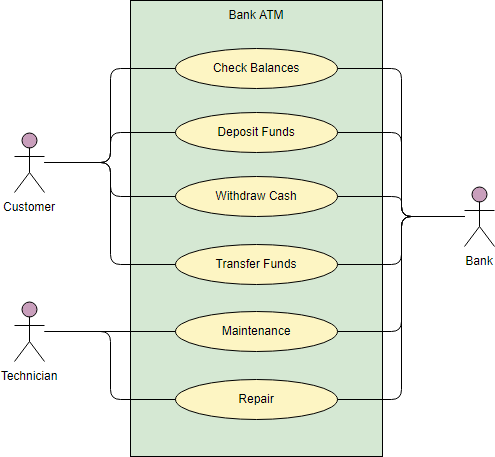
Here I choose some example from Visual Paradigm Online that you should be quite familiar with the business, such as ATM, DMS, and order system. The figure below shows an ATM use case diagram example, which is quite a classic example to use in teaching use case diagram.
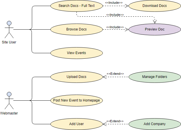
The Document Management System (DMS) use case diagram example below shows the actors and use cases of the system. In particular, there are include and extend relationships among use cases.
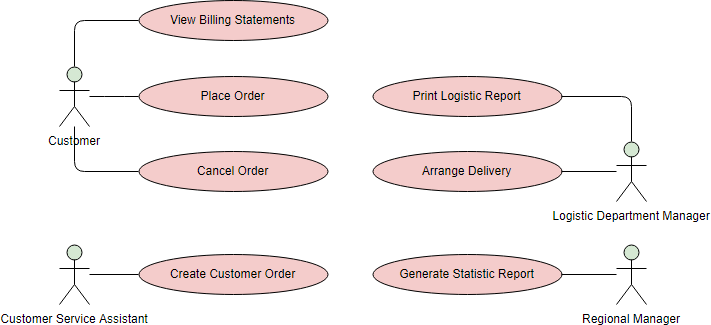
The Order System use case diagram example below shows the actors and use cases involved in the system:
Learn Other UML Diagram and Related Articles
- Why UML Modeling?
- Overview of the 14 UML Diagram Types
- What is Class Diagram?
- What is Component Diagram?
- What is Deployment Diagram?
- What is Object Diagram?
- What is Package Diagram?
- What is Composite Structure Diagram?
- What is Profile Diagram?
- What is Use Case Diagram?
- What is Activity Diagram?
- What is State Machine Diagram?
- What is Sequence Diagram?
- What is Communication Diagram?
- What is Interaction Overview Diagram?
- What is Timing Diagram
- What is UML Collaboration Diagram?
This post is also available in Deutsch, Español, فارسی, Français, English, Bahasa Indonesia, 日本語, Polski, Portuguese, Ру́сский, Việt Nam, 简体中文 and 繁體中文.