Introduction
Unified Modeling Language (UML) has established itself as the industry standard for modeling software systems, providing a common language for developers, architects, and stakeholders. Among the various diagram types in UML, the Class Diagram stands out as a fundamental tool for representing the static structure of a system. It visualizes classes, their attributes, methods, and the intricate relationships that bind them together.
However, possessing knowledge of UML notation is only half the battle. To truly unleash the power of visual modeling, one needs a robust tool that supports not just drawing, but comprehensive model management, traceability, and integration with modern development processes. This is where Visual Paradigm excels. Unlike simple diagramming tools that produce standalone images, Visual Paradigm offers an enterprise-grade modeling environment that supports the latest UML 2.x standards, integrates with Agile methodologies, and facilitates code engineering.
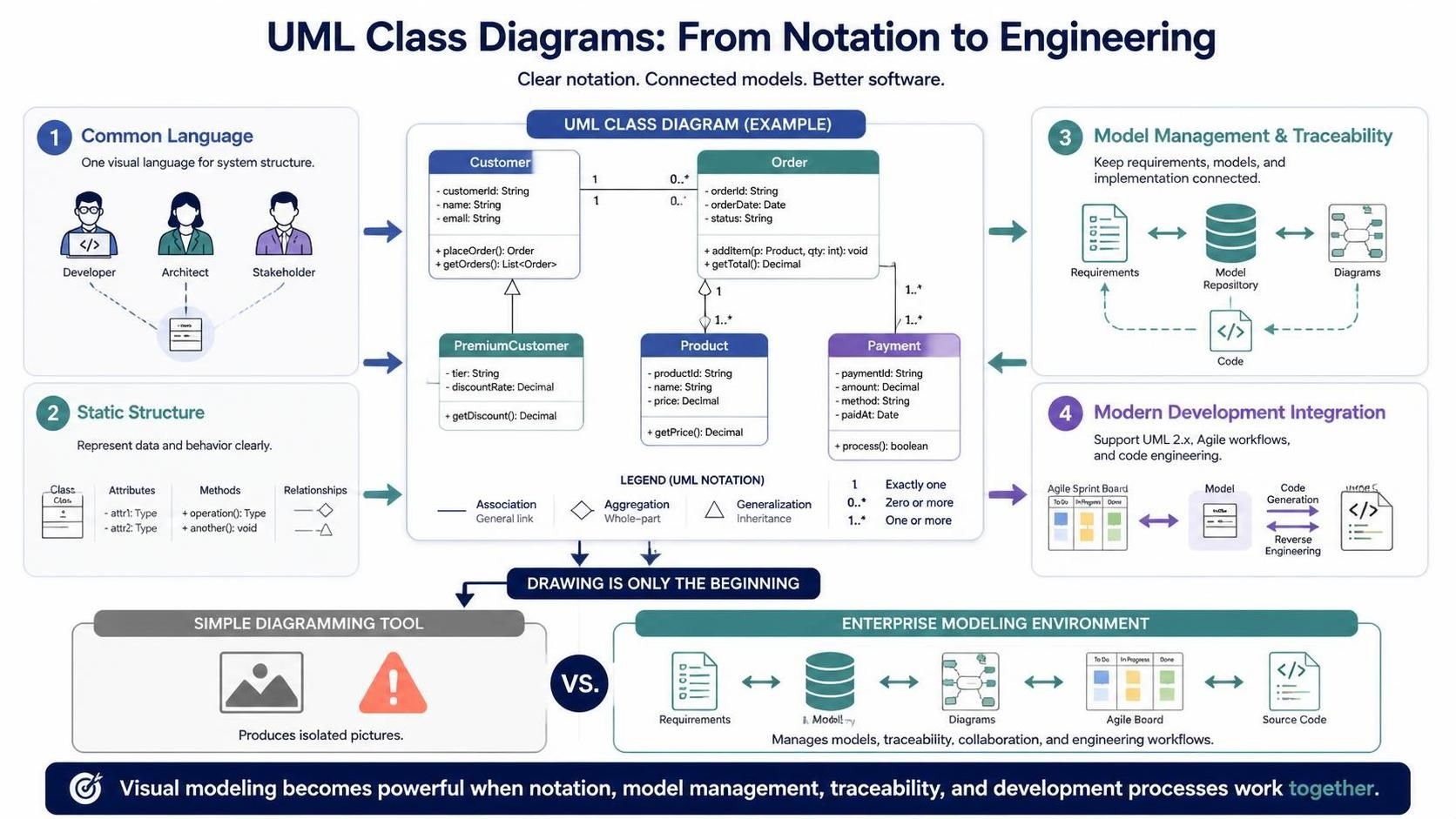
This guide explores how to effectively create and manage UML Class Diagrams using Visual Paradigm, highlighting key concepts, best practices, and the advanced features that make it the best UML tool for visual modeling.

Get Started

Understanding Key Concepts in Class Diagrams
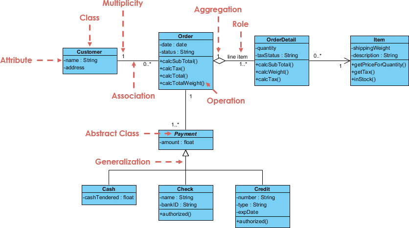
Before diving into the tool, it is essential to understand the core components of a Class Diagram. These elements form the backbone of object-oriented design.
1. Classes
A class is the blueprint for objects in a system. In Visual Paradigm, classes are represented as rectangles divided into three compartments:
-
Top Section: Contains the class name.
-
Middle Section: Lists the attributes (properties or data) of the class.
-
Bottom Section: Lists the operations (methods or functions) the class can perform.
2. Attributes and Methods
-
Attributes: Define the state of an object. For example, a
Customerclass might have attributes likename,email, andcustomerId. -
Methods: Define the behavior of an object. For the
Customerclass, methods might includelogin(),updateProfile(), orplaceOrder().
3. Relationships
Classes rarely exist in isolation. UML defines several types of relationships to show how classes interact:
-
Association: A structural relationship indicating that objects of one class are connected to objects of another.
-
Inheritance (Generalization): A relationship where a child class inherits properties and behaviors from a parent class.
-
Aggregation & Composition: Special forms of association representing “whole-part” relationships, with composition implying a stronger lifecycle dependency.
-
Dependency: A relationship where a change in one class may affect another.
Why Visual Paradigm? Addressing Common Challenges
Many teams start with web-based diagrammers or general-purpose tools like Visio. While these may seem attractive due to zero configuration, they often fall short in enterprise-scale scenarios.
-
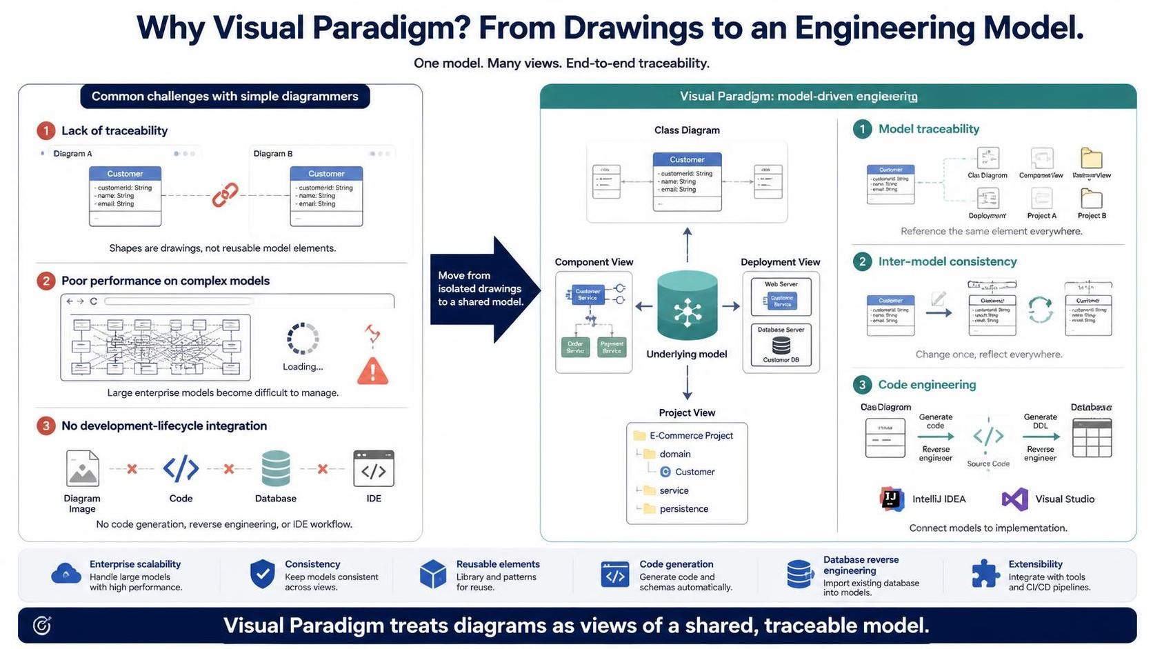
Lack of Traceability: In simple diagramming tools, shapes are just drawings. If you create a “Customer” class in one diagram, you cannot reference it in another. This leads to inconsistencies and duplicated effort.
-
Poor Performance on Complex Models: Web-based tools often struggle with large, complex diagrams, lacking the performance needed for enterprise architecture.
-
No Integration with Development Lifecycle: Tools like Visio produce static images. They do not support code generation, database reverse engineering, or integration with IDEs like IntelliJ or Visual Studio.
Visual Paradigm solves these issues by treating diagrams as views of an underlying model. This allows for:
-
Model Traceability: Reference the same model element across multiple diagrams and projects.
-
Inter-Model Consistency: Changes in one view reflect everywhere.
-
Code Engineering: Generate code from class diagrams or reverse-engineer code into diagrams.
Step-by-Step: Creating a Class Diagram in Visual Paradigm
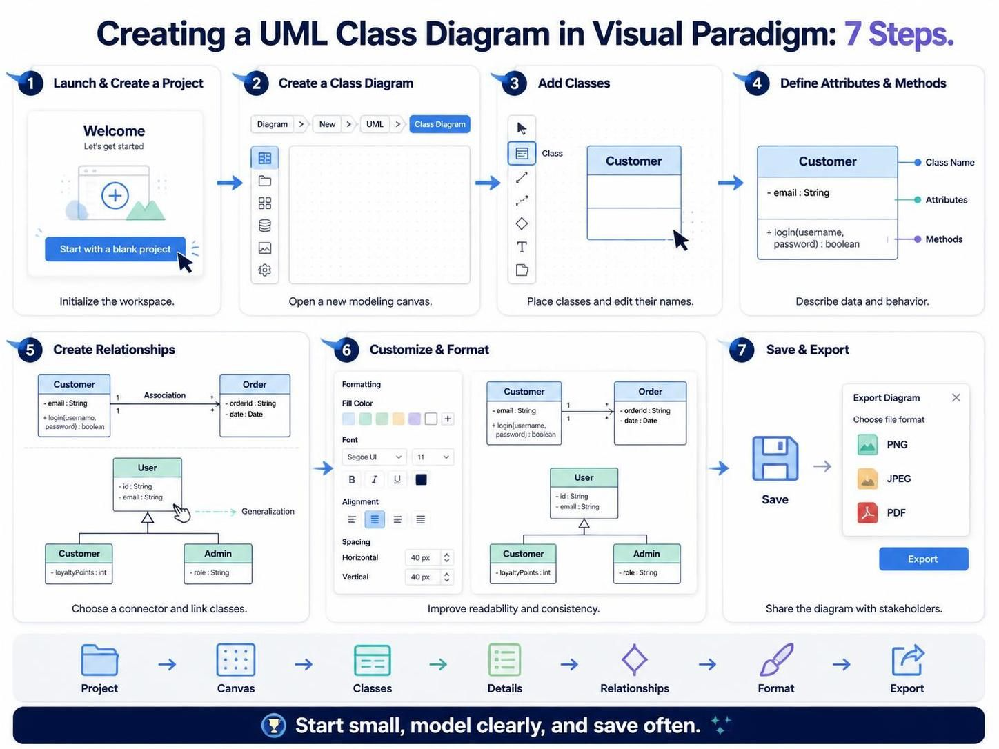
Visual Paradigm provides an intuitive interface for creating professional class diagrams. Follow these steps to get started.
Step 1: Launch and Create a Project
Open Visual Paradigm and select “Start with a blank project.” This initializes your workspace.
Step 2: Create a New Class Diagram
-
Navigate to the main menu and select Diagram > New > UML > Class Diagram.
-
A new canvas will open, ready for modeling.
Step 3: Add Classes
-
Click on the Class icon in the toolbar.
-
Click anywhere on the canvas to place a new class shape.
-
Double-click the class to edit its name. You can also right-click to access more detailed options.
Step 4: Define Attributes and Methods
-
In the class details window (or by editing directly on the shape), add attributes in the middle section. Use the format
visibility name : type(e.g.,- email : String). -
Add methods in the bottom section using the format
visibility name(parameters) : returnType(e.g.,+ login(username, password) : boolean).
Step 5: Create Relationships
-
Select the appropriate relationship connector from the toolbar (e.g., Association, Generalization).
-
Click and drag from the source class to the target class.
-
Visual Paradigm will automatically adjust the line style and arrows based on the UML standard selected.
Step 6: Customize and Format
Enhance readability by customizing colors, fonts, and layout. Use the formatting panel to align elements, distribute spacing, and apply consistent styles across your diagram.
Step 7: Save and Export
Save your project regularly. When sharing with stakeholders who may not have Visual Paradigm, export your diagram to PNG, JPEG, or PDF via File > Export.
Advanced Features for Enterprise Modeling
Visual Paradigm goes beyond basic diagramming with features designed for complex software development lifecycles.
Integrate UML with Agile / Scrum Process
-
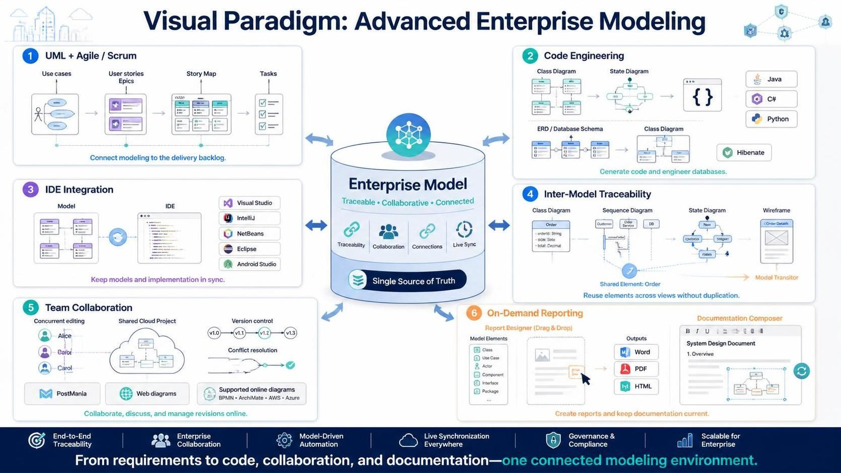
From Use Cases to Backlog: Seamlessly integrate use case modeling with agile development. Transform use cases into user stories or epics and manage them in a story map.
-
Task Management: Break down user stories into tasks managed automatically within the tool.
Code Engineering Toolset
-
Code Generation: Generate skeleton code in popular languages (Java, C#, Python, etc.) directly from your class and state diagrams.
-
Database Engineering: Generate database schemas from ERDs and map them to class diagrams using frameworks like Hibernate.
-
IDE Integration: Sync your models with leading IDEs including Visual Studio, IntelliJ, NetBeans, Eclipse, and Android Studio.
Inter-Model Traceability
-
Model References: Use the same model element in multiple diagrams without duplication.
-
Model Transitor: Identify classes from sequence diagrams and transition between different model types effortlessly.
-
Wireframing: Elaborate use case scenarios with built-in wireframe tools.
Team Collaboration
-
Concurrent Editing: Teams can work on the same project simultaneously with automatic version control and conflict resolution.
-
PostMania: Share, discuss, and comment on diagrams online via the cloud.
-
Web Diagrams: Access and edit diagrams online, including BPMN, ArchiMate, and AWS/Azure diagrams, at no additional cost.
On-Demand Report Designer
-
Custom Reports: Drag and drop model elements to compose reports in Word, PDF, or HTML.
-
Documentation Composer: Embed live model elements into corporate documents for up-to-date documentation.
Best Practices for Effective Class Diagrams
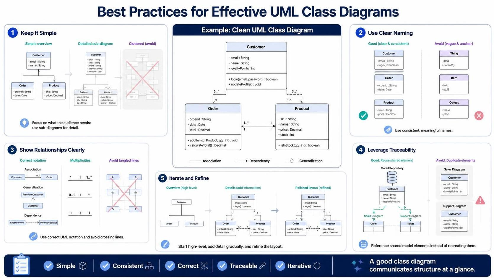
-
Keep it Simple: Avoid clutter. Focus on the most critical classes and relationships for the specific audience. Use sub-diagrams for detailed elaboration.
-
Use Clear Naming Conventions: Adopt consistent naming for classes, attributes, and methods to enhance readability and maintainability.
-
Show Relationships Clearly: Use correct UML notation for associations, inheritances, and dependencies. Avoid crossing lines where possible.
-
Leverage Traceability: Instead of recreating classes in different diagrams, use model references to ensure consistency and reduce maintenance overhead.
-
Iterate and Refine: Start with a high-level overview and gradually add details. Use Visual Paradigm’s layout tools to keep diagrams clean as they grow.
Conclusion
Class diagrams are indispensable for visualizing the static structure of software systems. While many tools allow you to draw boxes and lines, Visual Paradigm empowers you to build a living model that integrates with your entire development lifecycle. From Agile backlog management to code generation and team collaboration, it provides the comprehensive toolset needed for modern software engineering.
By following the steps and best practices outlined in this guide, you can create clear, accurate, and actionable class diagrams that enhance communication among team members and improve the overall quality of your software architecture. Whether you are a solo developer or part of a large enterprise team, Visual Paradigm offers the scalability and depth required to master UML modeling.
Recommended Resources
-
Mastering Sequence Diagram Modeling: A Practical Approach with Visual Paradigm: Step-by-step guide for creating sequence diagrams using practical examples like order placement.
-
From Prompt to Publication: Mastering AI-Driven UML Modeling Using Diagram-as-Code with Visual Paradigm: Explores AI-assisted diagram generation and a code-as-diagram workflow for living documentation.
-
Practical 3: Structural Implementation: Hands-on tutorial for generating class, component, and deployment diagrams for a Library Management System.
- Beyond Pretty Pictures: A Modern Guide to Analysis and Design with AI, Diagram-as-Code, and Visual Paradigm: Modern overview of combining AI, code-based diagrams, and collaboration features.
-
UML in the Age of AI: How Visual Paradigm’s Ecosystem is Reviving Visual Modeling (2025): Discusses UML’s relevance in modern development and the role of AI-powered tooling.
-
How to Create UML Use Case Diagram in Visual Paradigm: Step-by-step guide for creating use case diagrams in the desktop application.
-
UML Team Collaboration: Mastering Version Control & Modeling: Covers branching strategies, peer review, and collaborative modeling with version control.