


Introduction
In the rapidly evolving landscape of software engineering, managing complexity has become one of the most critical challenges facing development teams. As systems grow in size and sophistication, traditional approaches to documentation and design often fall short, leading to miscommunication, costly errors, and project failures. This is where modeling languages play a pivotal role, serving as the bridge between abstract concepts and concrete implementations.
The Unified Modeling Language (UML) has emerged as the de facto standard for software modeling, providing a common vocabulary that enables stakeholders across different domains to communicate effectively. Whether you’re a business analyst capturing requirements, a software architect designing system structure, or a developer implementing functionality, UML offers the tools necessary to visualize, specify, construct, and document software-intensive systems.
This comprehensive case study explores the fundamental concepts of modeling, traces the historical evolution of UML, and examines how this unified language has transformed the way we approach software development. By understanding the principles behind UML and its practical applications, organizations can leverage these powerful techniques to master complex systems, reduce development risks, and deliver higher-quality software solutions.
Understanding Models: The Foundation of Effective Communication
What is a Model?
At its core, a model is a simplified representation of reality. Just as an architectural blueprint captures the essential elements of a building while omitting unnecessary details like the color of individual bricks, a software model focuses on the important aspects of a system while abstracting away implementation specifics. This selective representation allows us to work with complex systems in manageable ways.
The power of models lies in their ability to be represented in various media—two-dimensional diagrams, three-dimensional visualizations, textual descriptions, or interactive prototypes. This flexibility means we can choose the most appropriate representation for our specific needs and audience.
A model of a software system developed using a modeling language like UML possesses both semantics (meaning) and notation (symbols and syntax). These models can take multiple forms, combining visual diagrams with textual specifications. The key advantage is that models are designed to be easier to manipulate and understand for specific purposes than the final, fully implemented system.

Figure 1: A model provides a simplified view that captures essential aspects while filtering out unnecessary complexity
Why Do We Need Models?
Models serve multiple critical purposes throughout the software development lifecycle:
1. Capturing Requirements and Domain Knowledge
Models enable precise articulation of requirements and domain expertise, ensuring all stakeholders—from business users to technical teams—can understand and agree on what needs to be built. This shared understanding reduces ambiguity and prevents costly misunderstandings later in the project.
2. Facilitating Design Thinking
Before writing a single line of code, models allow architects and designers to think through system structure, behavior, and interactions. This upfront thinking helps identify potential issues early when they’re least expensive to fix.
3. Documenting Design Decisions
Models capture design decisions in a mutable form that remains separate from requirements. This separation allows teams to explore different design alternatives without compromising the original requirements, and provides a historical record of why certain choices were made.
4. Generating Work Products
Well-constructed models can serve as the foundation for generating various work products, including code skeletons, test cases, documentation, and deployment configurations. This automation improves consistency and reduces manual effort.
5. Managing Information in Large Systems
For enterprise-scale systems with millions of lines of code and hundreds of components, models provide mechanisms to organize, filter, retrieve, examine, and edit information efficiently. They act as navigational aids through the complexity.
6. Exploring Solutions Economically
Models enable rapid exploration of multiple design alternatives at a fraction of the cost of full implementation. Teams can evaluate trade-offs, assess feasibility, and select optimal solutions before committing significant resources.
7. Mastering Complex Systems
Perhaps most importantly, models help humans comprehend systems that would otherwise be too complex to understand in their entirety. By providing different views and levels of abstraction, models make the incomprehensible comprehensible.
The Unified Modeling Language: A Standard for Software Modeling
What is UML?
The Unified Modeling Language (UML) is a standardized visual modeling language specifically designed for software-intensive systems. It provides a comprehensive set of diagram types and notation rules that enable practitioners to:
-
Visualize system architecture and behavior
-
Specify detailed requirements and designs
-
Construct system blueprints that guide implementation
-
Document decisions and structures for future reference
In essence, UML serves as a common language that bridges the communication gap between different stakeholders in software projects, from business analysts and project managers to developers and testers.
The Creators of UML
UML was developed by three pioneering figures in object-oriented software engineering:
-
Grady Booch: Known for the Booch Method, which emphasized object-oriented analysis and design
-
James Rumbaugh: Creator of Object-Modeling Technique (OMT), focusing on data modeling and system structure
-
Ivar Jacobson: Developer of Objectory, which introduced use case-driven development
These three visionaries came together at Rational Corporation, combining their complementary methodologies into a unified approach that would eventually become the industry standard.
UML: A Language, Not a Methodology
It’s crucial to understand that UML is a modeling language, not a software development methodology. While it provides the notation and semantics for creating models, it doesn’t prescribe how to manage projects, organize teams, or sequence development activities.
A software system comprises multiple elements beyond just code:
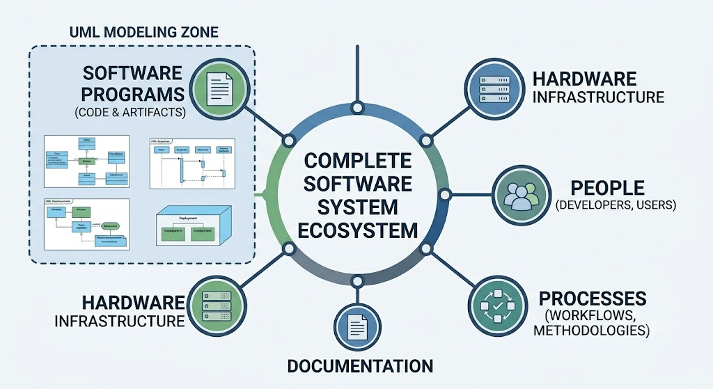
Figure 2: A complete software system includes programs, hardware infrastructure, people, processes, and documentation
UML helps model the software artifacts within this broader ecosystem but doesn’t dictate how to build or manage the entire system. Organizations typically combine UML with specific methodologies like Agile, Waterfall, or Rational Unified Process (RUP) to create comprehensive development frameworks.
The Evolution of UML: A Historical Journey
The development of UML represents one of the most successful standardization efforts in software engineering history. Its evolution reflects the industry’s growing recognition of the need for common modeling standards.
Timeline of UML Development
1993: The Beginning
Grady Booch was working at Rational Corporation, developing and refining his Booch Method for object-oriented analysis and design. His approach emphasized iterative development and comprehensive modeling techniques.
1994: First Unification Attempt
James Rumbaugh joined Rational Corporation, bringing his Object-Modeling Technique (OMT) with him. The first major unification effort began, attempting to combine:
-
Booch’s methodological concepts
-
Rumbaugh’s OMT notation and techniques
-
CRC (Class-Responsibility-Collaboration) cards for design
This initial collaboration laid the groundwork for what would become UML, though the resulting notation was still evolving.
1995: The Third Pioneer Joins
Ivar Jacobson joined Rational Corporation, introducing his Objectory methodology with its strong emphasis on use cases and user-centered design. The second and more comprehensive unification attempt combined:
-
Booch’s concepts and notation
-
Rumbaugh’s OMT
-
Jacobson’s Objectory and use case approach
This three-way merger was officially named the Unified Modeling Language (UML), marking a significant milestone in software modeling standardization.
1996: Seeking Industry Recognition
Rational Corporation submitted a proposal to the Object Management Group (OMG), a consortium of technology companies focused on establishing industry standards. The goal was to have UML recognized as an open, vendor-neutral standard rather than a proprietary Rational product.
1997: OMG Standardization
The Object Management Group officially adopted UML as a standard modeling language. This recognition was crucial because it:
-
Ensured UML would remain open and accessible
-
Encouraged widespread industry adoption
-
Prevented fragmentation into competing proprietary standards
-
Established governance for future evolution
2000: International Recognition
The International Organization for Standardization (ISO) recognized UML version 1.0 as an international standard. This global endorsement further solidified UML’s position as the premier software modeling language and facilitated its adoption worldwide.
2004: Major Upgrade to UML 2.0
A significant revision resulted in UML 2.0, which introduced:
-
Enhanced precision and clarity in semantics
-
New diagram types for specific purposes
-
Improved support for component-based development
-
Better alignment with modern software engineering practices
-
More rigorous formal foundations
UML 2.0 represented a maturation of the language, addressing limitations identified during years of practical use.
2011: Latest Version
UML version 2.4.1 was published in August 2011, representing incremental improvements and clarifications to the 2.0 specification. This version continues to serve as the current standard, demonstrating the stability and maturity of the UML specification.
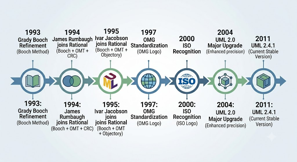
Figure 3: The historical timeline showing key milestones in UML’s development from initial concept to international standard
The Meaning of “Unified” in UML
The term “Unified” in Unified Modeling Language carries significant meaning, reflecting the language’s comprehensive scope and integrative nature. UML achieves unification across multiple dimensions:
1. Across Historical Methods and Notations
UML successfully integrated three previously competing approaches:
-
Booch Method: Emphasized object-oriented design with rich notation for classes and objects
-
OMT (Object-Modeling Technique): Focused on data modeling and system structure
-
Objectory: Introduced use cases and scenario-based development
By synthesizing the best elements of each, UML created a more powerful and flexible notation than any of its predecessors alone.
2. Across Development Life Cycle Phases
Unlike earlier modeling approaches that focused primarily on either analysis or design, UML supports the entire software development lifecycle:
-
Requirements gathering: Use case diagrams capture functional requirements
-
Analysis: Class diagrams, activity diagrams model problem domain
-
Design: Component diagrams, deployment diagrams specify architecture
-
Implementation: Detailed class diagrams guide coding
-
Testing: State machine diagrams support test case development
-
Deployment: Deployment diagrams show physical distribution
This end-to-end coverage ensures continuity and traceability throughout the project.
3. Across Application Domains
UML isn’t limited to specific types of software. It has been successfully applied to:
-
Business process modeling
-
Real-time embedded systems
-
Web applications
-
Enterprise systems
-
Mobile applications
-
Database design
-
Service-oriented architectures
This domain independence makes UML a versatile tool applicable across industries.
4. Across Implementation Languages and Platforms
UML models are independent of specific programming languages or platforms. The same UML diagram can guide implementation in:
-
Java
-
C++
-
C#
-
Python
-
JavaScript
-
And many other languages
This language neutrality protects investments in modeling and facilitates migration between technologies.
5. Across Development Platforms
Whether teams use:
-
Traditional IDEs
-
Cloud-based development environments
-
Specialized modeling tools
-
Open-source frameworks
UML provides a consistent notation that transcends tool boundaries, enabling collaboration regardless of technical infrastructure.
6. Across Internal Concepts
UML unifies various conceptual perspectives on software systems:
-
Structural views: What things exist (classes, objects, components)
-
Behavioral views: How things behave and interact (activities, states, sequences)
-
Architectural views: How things are organized (packages, layers, tiers)
-
Implementation views: How things are realized (code, databases, interfaces)
This multi-perspective approach ensures comprehensive coverage of system concerns.
Practical Applications: UML in Action
Case Example: E-Commerce Platform Development
To illustrate how UML addresses real-world challenges, consider a company developing a new e-commerce platform. Here’s how different UML diagrams serve specific purposes:
Requirements Phase
-
Use Case Diagrams: Capture customer interactions (browse products, add to cart, checkout)
-
Activity Diagrams: Model business processes (order fulfillment workflow)
Analysis Phase
-
Class Diagrams: Identify domain entities (Product, Customer, Order, Payment)
-
Sequence Diagrams: Show interactions between objects during key scenarios
Design Phase
-
Component Diagrams: Define modular architecture (catalog service, payment gateway, inventory system)
-
Deployment Diagrams: Specify infrastructure (web servers, database clusters, CDN)
Implementation Support
-
Detailed Class Diagrams: Guide developers with attributes, methods, and relationships
-
State Machine Diagrams: Model complex object lifecycles (order status transitions)
Documentation and Maintenance
-
Package Diagrams: Organize codebase structure for new team members
-
Communication Diagrams: Document runtime interactions for troubleshooting
Through this comprehensive modeling approach, the team maintains clarity despite system complexity, facilitates onboarding of new developers, and creates living documentation that evolves with the system.
Benefits and Limitations of UML
Key Benefits
Standardization
UML provides a common language understood globally, reducing learning curves when team members change or when collaborating across organizational boundaries.
Precision
Well-defined semantics eliminate ambiguity that plagues natural language specifications, reducing misinterpretation and rework.
Abstraction
Multiple diagram types allow viewing systems at different levels of detail, from high-level architecture to implementation specifics.
Tool Support
Extensive ecosystem of modeling tools provides features like:
-
Automatic code generation
-
Reverse engineering from code
-
Consistency checking
-
Version control integration
-
Collaboration features
Early Problem Detection
Modeling reveals design flaws before implementation begins, when correction costs are minimal compared to post-implementation fixes.
Recognized Limitations
Learning Curve
Mastering UML requires significant investment in training and practice. Teams must learn both notation and underlying concepts.
Over-Engineering Risk
Excessive focus on comprehensive modeling can lead to “analysis paralysis,” delaying actual development and creating maintenance burdens.
Tool Dependency
While UML itself is tool-independent, effective large-scale modeling often requires sophisticated tools, creating potential vendor lock-in.
Not a Silver Bullet
UML doesn’t replace good engineering practices, domain expertise, or effective communication. It’s a tool that amplifies existing capabilities rather than substituting for them.
Agile Tension
Some agile practitioners view extensive upfront modeling as contradictory to iterative, adaptive development, though lightweight UML usage can complement agile practices effectively.
Best Practices for UML Adoption
Based on decades of industry experience, several best practices have emerged for effective UML usage:
1. Right-Scale Your Modeling
Create models proportional to system complexity and project risk. Simple systems need simple models; complex systems justify comprehensive modeling.
2. Focus on Communication
Remember that models exist to facilitate understanding. Prioritize clarity over completeness, and tailor diagrams to your audience.
3. Maintain Living Models
Keep models synchronized with implementation through regular updates, automated generation where possible, and treating models as first-class artifacts.
4. Use Multiple Views
Leverage different diagram types to address different stakeholder concerns. No single diagram type captures everything.
5. Iterate and Refine
Start with rough sketches, refine based on feedback, and evolve models as understanding deepens. Perfection isn’t the goal; usefulness is.
6. Combine with Methodology
Integrate UML with your chosen development methodology, whether Agile, Waterfall, or hybrid approaches, adapting practices to your context.
7. Invest in Training
Ensure team members understand both UML notation and modeling principles. Poorly constructed models can mislead rather than clarify.
Visual Paradigm: Bridging Business Goals and Technical Implementation with UML
Comprehensive UML 2.x Modeling
- Structural Diagrams: Includes Class, Object, Component, Deployment, Package, and Composite Structure diagrams.
- Behavioral Diagrams: Covers Use Case, Sequence, Activity, State Machine, Communication, Timing, and Interaction Overview diagrams.
Code Engineering and Synchronization
- Round-Trip Engineering: Users can generate code directly from UML class models. Conversely, updates to source code seamlessly push changes back to the visual model.
- Multi-Language Support: The platform supports forward and reverse engineering for a wide range of languages, including Java, C#, C++, Python, PHP, Ruby, and VB.NET.
- IDE Integration: Visual Paradigm can be embedded as a plugin directly inside popular Integrated Development Environments (IDEs) such as IntelliJ IDEA, Eclipse, NetBeans, Visual Studio, and Android Studio.
- Sequence Code Generation: Teams can study the runtime behavior of applications by reverse-engineering functional UML sequence diagrams directly from active Java code logic.
Integrated AI Diagram Generator
- Natural Language to UML: Users can interact with an AI chatbot to describe system logic. The AI interprets these requirements, instantly mapping out entities, relationships, and elements.
- AI Workflows: The system delivers guided web-app workflows to dynamically alter, update, and validate syntax for intricate diagrams.
Efficient Layout & Model Management
- Resource Catalog: This efficiency tool allows users to quickly construct shapes and automatically validates element connections to prevent syntax mistakes.
- Element Reusability: A single model element can be reused across multiple views and distinct diagrams while retaining its universal properties.
- Model Traceability: The system tracks cascading effects using sub-diagrams and “Model Transitors,” allowing users to view how a modification in one location alters connected components elsewhere.
Agile Workspace & Collaboration
- Cloud Collaboration: Multiple team members can concurrently co-create complex system architectures while managing automatic version histories and merges.
- PostMania: A feedback loop platform that allows internal and external stakeholders to share, discuss, and pin comments directly onto visual assets online.
- Story Mapping & Backlogs: The tool bridges UML diagrams directly with user story maps, sprint backlogs, task managers, and Kanban boards.
- On-Demand Reports: A drag-and-drop document composer generates professional system blueprints into Word, PDF, or HTML formats.
Available Editions
- Community Edition (Desktop): Completely free for non-commercial use, offering basic offline UML 2.x modeling.
- Visual Paradigm Online (Free Edition): A zero-installation web alternative offering unconstrained shape limits for basic diagrams with Google Drive syncing.
- Paid Commercial Tiers: Subscriptions range from a “Modeler” package up to enterprise-level tiers that unlock advanced code reversal, team database engineering, and comprehensive agile project spaces.
Conclusion
The Unified Modeling Language represents a remarkable achievement in software engineering standardization, providing a common vocabulary that has transformed how organizations approach complex system development. From its origins in the mid-1990s through the collaborative efforts of Booch, Rumbaugh, and Jacobson, to its recognition as an international standard, UML has proven its value across diverse industries and application domains.
Understanding models as simplified representations that capture essential aspects while filtering noise is fundamental to leveraging UML effectively. Models serve multiple critical purposes—from capturing requirements and facilitating design thinking to managing information in large systems and exploring solutions economically. These benefits explain why modeling has become indispensable in modern software engineering.
The “unified” nature of UML—spanning historical methods, development phases, application domains, implementation technologies, and conceptual perspectives—makes it uniquely positioned to address the multifaceted challenges of contemporary software development. While not without limitations, and certainly not a replacement for sound engineering judgment, UML provides powerful tools for mastering complexity when applied thoughtfully and appropriately scaled.
As software systems continue to grow in sophistication, the principles embodied in UML remain increasingly relevant. Whether you’re embarking on your first modeling project or seeking to refine existing practices, understanding UML’s foundations, evolution, and proper application will enhance your ability to design, communicate, and deliver successful software solutions. The journey from abstract requirements to concrete implementation becomes more manageable, more predictable, and ultimately more successful when guided by well-crafted models.
The future of software modeling may bring new notations and tools, but the fundamental insights that UML codifies—the value of abstraction, the importance of multiple perspectives, and the power of standardized communication—will endure as timeless principles of effective software engineering.
References
- Visual Paradigm Features: UML Tool: Overview of the comprehensive UML modeling features and suites available within the Visual Paradigm ecosystem.
- Visual Paradigm: Your Complete Guide to UML Modeling: A guide covering Visual Paradigm’s capabilities from free beginner tools to advanced AI-powered solutions.
- Visual Paradigm: A Comprehensive UML Modeling Solution: Blog post detailing the comprehensive nature of Visual Paradigm as a UML modeling solution.
- Comprehensive UML Tools: Information on Visual Paradigm’s suite of comprehensive UML tools for software design.
- What is UML?: An introductory guide explaining the basics of Unified Modeling Language within the Visual Paradigm context.
- Visual Paradigm: A Comprehensive UML Modeling Solution: Additional insights into the comprehensive modeling capabilities of the platform.
- Unified Modeling Language (UML) Versions and Tools: An article discussing various UML versions and the tools available, including Visual Paradigm.
- A Comprehensive Case Study of Visual Paradigm’s Free UML Modeling Tiers: A detailed look at the free modeling tiers available for non-commercial use.
- Visual Paradigm User Guide: Documentation supporting the use of specific UML diagram types and features.
- Online Visual Paradigm: UML Tool Features: Features specific to the online version of the UML tool.
- Free UML Tool: Details on the free UML tool offerings and their capabilities.
- Code Engineering Tools: In-depth information on round-trip engineering, multi-language support, and code synchronization features.
- UML Tool Solution: Overview of the UML tool solution, including IDE integration and reporting capabilities.
- Visual Paradigm Gallery: A gallery showcasing examples of diagrams and models created with Visual Paradigm.
- Overview of the 14 UML Diagram Types: A guide providing an overview of the different UML diagram types supported.
- AI Object Diagram Generator: Guide on using the AI generator for creating object diagrams.
- Visual Paradigm Video Tutorial: Video content demonstrating Visual Paradigm features and usage.
- AI Sequence Diagram Generator: Guide on using the AI generator for creating sequence diagrams.
- Agile UML Diagram Tool: Information on features tailored for agile development teams, including collaboration and story mapping.
- Full Featured UML Tool: Details on the full-featured capabilities of the UML tool, including model management and traceability.
- Comprehensive UML Tools (CN): Chinese language resource detailing comprehensive UML tools.
- Full Featured UML Tool: Additional details on the full-featured UML tool capabilities.
- Free Online UML Tool: Information on the free online version of the UML tool.
- Free UML Tool: Details on the free UML tool available online.
- Support FAQ: Frequently asked questions regarding Visual Paradigm editions and features.
This post is also available in Deutsch, Español, فارسی, Français and Bahasa Indonesia.