


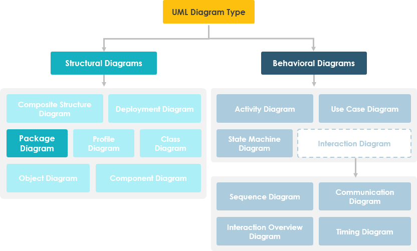
Introduction
As software systems grow in complexity, the challenge of maintaining clear, navigable architectural documentation becomes increasingly critical. After years of working with enterprise-scale applications and various modeling tools, I’ve found that UML’s Package and Component diagrams—when used effectively in Visual Paradigm—offer an unparalleled way to bring order to chaos. This guide shares my hands-on experience organizing large systems, reducing coupling, and communicating architecture to both technical and non-technical stakeholders. Whether you’re a seasoned architect or a developer stepping into system design for the first time, this walkthrough will help you leverage Visual Paradigm’s capabilities to create maintainable, insightful diagrams that actually get used.

Package Diagram
Big systems offer special challenges. Developing use case or class models for a large system is often complex and ends up with too many shapes and relationships to fit into a single page. A useful technique to handle this is UML’s packages. A package diagram in the Unified Modeling Language depicts the dependencies between the packages that make up a model. The overall picture of the system is the picture of packages and their dependencies; the aim is to keep the dependencies down to a minimum.
Package diagram, a kind of structural diagram, shows the arrangement and organization of model elements in middle to large scale projects. Package diagrams can show both structure and dependencies between sub-systems or modules, showing different views of a system—for example, as a multi-layered (aka multi-tiered) application model.
Purpose of Package Diagrams
Package diagrams are used to structure high-level system elements. Packages are used for organizing large systems which contain diagrams, documents, and other key deliverables.
-
Package Diagrams can be used to simplify complex class diagrams by grouping classes into packages.
-
A package is a collection of logically related UML elements.
-
Packages are depicted as file folders and can be used on any of the UML diagrams.
Other Related Package Diagram Articles
- What is UML?
- Why UML Modeling?
- Overview of the 14 UML Diagram Types
- What is Package Diagram?
- How to draw a Package Diagram in UML
How to Draw a Package Diagram in UML: My Step-by-Step Experience
Package diagram is a kind of UML diagram that shows the arrangement and organization of model elements in middle to large scale projects. It can show both structure and dependencies between sub-systems or modules.
Creating a Package Diagram: My Workflow
Perform the steps below to create a UML package diagram in Visual Paradigm. This is the exact workflow I use when starting a new architecture documentation effort:
-
Select Diagram > New from the application toolbar.
-
In the New Diagram window, select Package Diagram.
-
Click Next.
-
Enter the diagram name and description. The Location field enables you to select a model to store the diagram.
-
Click OK.
Creating Packages: Practical Tips
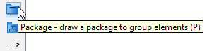
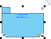
To create a package in a package diagram, click Package on the diagram toolbar and then click on the diagram.
A package will be created. I recommend naming packages using domain-driven design principles (e.g., OrderManagement, UserAuthentication) to improve clarity for cross-functional teams.
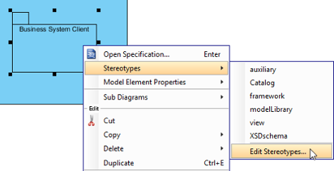
Assigning Stereotypes: Adding Semantic Meaning
One feature I find particularly valuable is the ability to assign stereotypes to packages. This helps convey architectural intent at a glance.
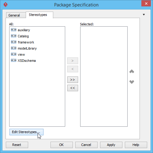
Right-click on the package and select Stereotypes > Edit Stereotypes… from the pop-up menu.
When the Package Specification window opens, with the Stereotypes tab selected, the list on the left shows the selectable stereotypes. If the stereotype you want to use is not on the list, click the Edit Stereotypes… button.
Click the Add… button in the Configure Stereotypes window.
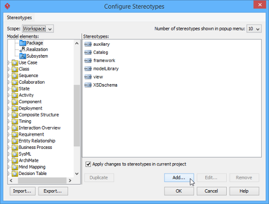
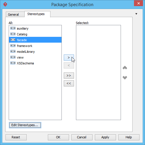
Enter a name for the new stereotype (e.g., facade, service-layer, infrastructure). Click OK in the Stereotype Specification window and the Configure Stereotypes window. You’ll see the added stereotype appear on the list in the Package Specification window. Select it and click Add Selected. Next, click OK to proceed.
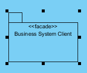
Close the specification window. Stereotypes will be applied to the package, making your diagram more expressive and self-documenting.
Continue to complete the diagram. I always review dependency arrows afterward to ensure we’re not creating circular references—a common pitfall in large systems.
Transitioning to Component Diagrams: When Packages Aren’t Enough
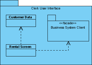
While package diagrams excel at organizing logical groupings, I’ve found that Component Diagrams become essential when you need to visualize physical deployment units, interfaces, and runtime dependencies. In Visual Paradigm, a Component Diagram is a UML structure diagram used to visualize the high-level physical structure and modular parts of a software system. It illustrates how various components—such as libraries, packages, and executable files—are wired together through interfaces to form a larger system. [1, 2, 3, 4]
What is Component Diagram?
Component Diagram – Visual Paradigm Community Circle
Key Concepts in Component Diagrams: What I Wish I’d Known Earlier
-
Component: A modular unit of software that encapsulates functionality and is independently replaceable. I treat these as deployment boundaries in microservices architectures.
-
Provided Interface: Represented by a “lollipop” symbol, this defines the services a component offers to others. Critical for contract-first API design.
-
Required Interface: Represented by a “socket” symbol, this specifies the services a component needs from its environment. Helps identify external dependencies early.
-
Port: An explicit point of interaction between a component and its environment. Useful for modeling adapter patterns and integration points.
-
Dependencies: Dashed arrows showing that one element requires another for its full implementation or operation. [2, 3, 5, 6, 7, 8]
Creating a Component Diagram in Visual Paradigm: My Tested Process
You can create these diagrams using the Visual Paradigm Desktop application or the web-based Visual Paradigm Online tool. [9, 10, 11, 12, 13] I typically start with Desktop for complex systems and use Online for collaborative reviews.
-
Start the Diagram: Select Diagram > New from the toolbar, choose Component Diagram, and click Next. [8, 10]
-
Add Components: Select the Component tool from the diagram toolbar and click on the canvas. Double-click to rename it. Pro tip: Use consistent naming conventions like
AuthService,PaymentGatewayto improve readability. [7, 8, 9, 10, 14] -
Define Interfaces:
-
To add a Provided Interface, mouse over a component, use the Resource Catalog button, drag it out, and select Realization -> Interface.
-
To add a Required Interface, use the Resource Catalog and select Usage -> Interface. [7, 8, 10, 15, 16]
-
-
Establish Relationships: Click a component and use the Resource Catalog to drag a dependency arrow to another component. I always validate that dependencies flow in one direction to avoid tight coupling. [8]
-
Utilize AI Features: Visual Paradigm now includes an AI Chatbot that can generate initial component diagrams based on text descriptions or brainstorm system architectures. I’ve used this for rapid prototyping before refining manually—saves significant time in early design phases. [17, 18]
For more detailed guidance and examples like a “Web Store” or “Order Processing System,” you can visit the Visual Paradigm Community Circle. These real-world examples helped me understand how to model e-commerce systems effectively. [4, 19, 20, 21]
Conclusion: Why This Approach Transformed My Architecture Practice
After integrating Package and Component diagrams into my regular workflow with Visual Paradigm, I’ve seen tangible improvements in team alignment, onboarding speed, and system maintainability. The key insight? Diagrams aren’t just documentation—they’re communication tools. By structuring large systems into logical packages and then mapping their physical component interactions, you create a living architecture that evolves with your codebase.
My recommendation: Start small. Pick one subsystem, model its packages, then drill into its components. Use stereotypes and interfaces intentionally—not decoratively. And leverage Visual Paradigm’s AI and collaboration features to keep diagrams current. When done right, these diagrams become the single source of truth that engineers, product managers, and stakeholders all reference. That’s when modeling stops feeling like overhead and starts delivering real value.
References
- What is UML?: A foundational guide explaining the Unified Modeling Language, its purpose, and core concepts for software modeling.
- Beginner’s Guide to Component Diagrams in UML: An accessible tutorial introducing component diagrams, their elements, and practical usage scenarios.
- UML Component Diagram Generator: An AI-powered tool within Visual Paradigm that helps generate component diagrams from natural language descriptions.
- Component Diagram Documentation: Comprehensive community documentation covering component diagram syntax, best practices, and advanced modeling techniques.
- Component Diagram Tutorial: Step-by-step interactive tutorial for creating component diagrams using Visual Paradigm Online.
- How to Draw a Component Diagram in UML: Detailed procedural guide with screenshots for building component diagrams from scratch.
- Drawing Component Diagrams: Official tutorial covering component creation, interface definition, and relationship mapping in Visual Paradigm.
- Component Diagram Software: Overview of Visual Paradigm Online’s component diagram capabilities, including collaboration and export features.
- Visual Paradigm User Guide: Component Diagrams: In-depth user guide section detailing advanced component diagram techniques and tool-specific workflows.
- Web Store Component Diagram Example: Real-world example of a component diagram modeling an e-commerce web store architecture.
- Component Diagram Video Tutorial: Video walkthrough demonstrating component diagram creation and best practices in Visual Paradigm.
- Creating Provided Interfaces: Specific guidance on modeling provided interfaces using the Resource Catalog in Visual Paradigm.
- Creating Required Interfaces: Step-by-step instructions for adding required interfaces to components in UML diagrams.
- What is Component Diagram?: Authoritative overview of component diagrams, their purpose, and key modeling elements in UML.
- AI-Powered Component Diagramming: Video demonstration of Visual Paradigm’s AI features for accelerating component diagram creation.
- Web Store Example – Community Circle: Community-contributed example showing a complete component diagram for a web store system.
- Component Diagram Category: Curated collection of component diagram articles, examples, and discussions from the Visual Paradigm community.
- Visual Paradigm Community Edition Guide: Guide to leveraging Visual Paradigm’s free Community Edition for UML modeling, including component and package diagrams.
This post is also available in Deutsch, Español, فارسی, Français, English, Bahasa Indonesia, 日本語, Polski, Portuguese, Ру́сский, Việt Nam, 简体中文 and 繁體中文.