


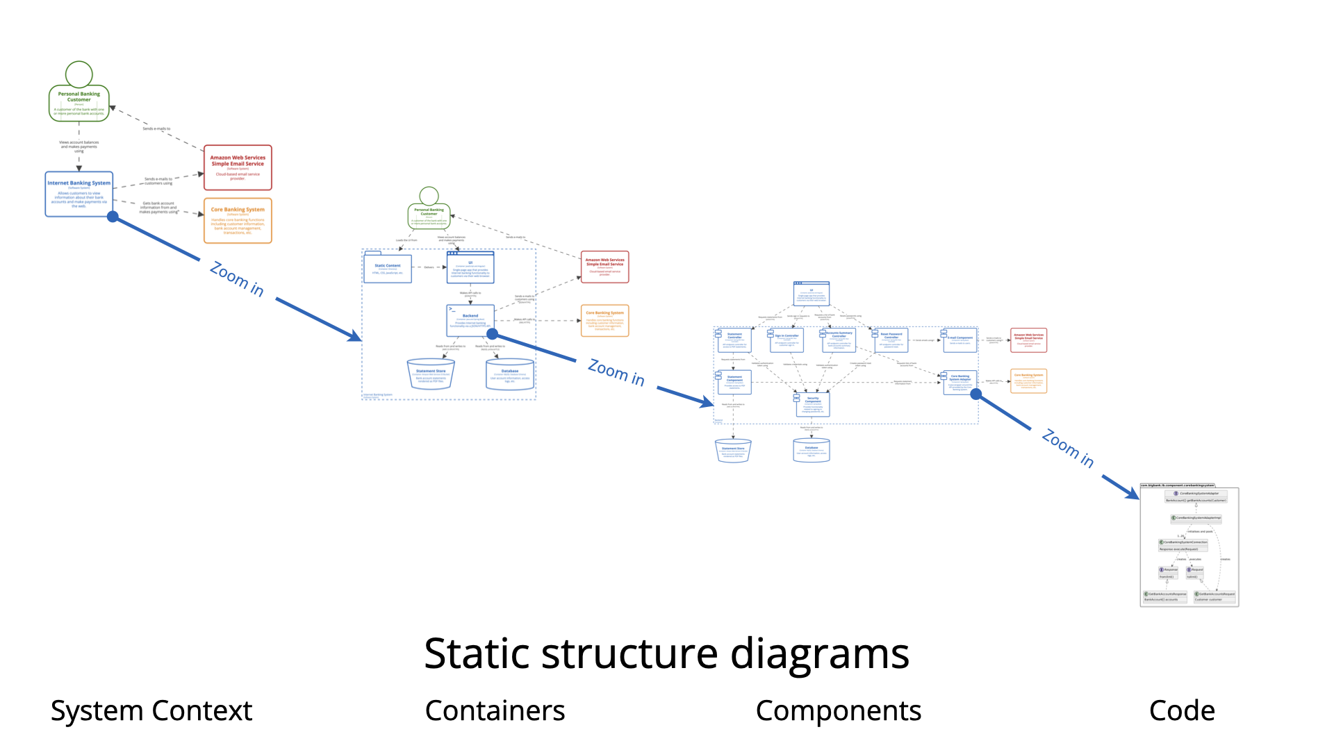
What is a C4 Component Diagram?
The Component diagram is Level 3 in Simon Brown’s C4 model. It zooms into one specific container (from the Level 2 Container diagram) to show:
-
The logical building blocks (components) that make up that container.
-
How those components interact with each other.
-
Responsibilities and implementation technologies (at a higher level than classes — think Spring Beans, modules, services, controllers, facades, etc.).
-
Key interfaces or contracts between components (often implied via relationships).
Important clarification: A “component” in C4 is not a class. It is a logical grouping of classes behind a well-defined interface — something that has a clear responsibility, can be developed/tested/deployed somewhat independently (within the container), but is not separately deployable like a container.
Examples of components:
-
REST Controller / Web Controller
-
Service / Use Case / Application Service
-
Repository / Data Access Object
-
Domain Model / Entity
-
Security / Authentication Module
-
Notification Sender
-
Facade to external system
-
Business Rule Engine
-
Caching Layer
The diagram remains logical / implementation-agnostic enough — no class attributes, methods signatures, or full UML class details (that’s Level 4 Code, which is optional and rare).
When to Create a Component Diagram
Create (and maintain) a Component diagram only when:
-
The chosen container is complex enough that its internal structure is not obvious from its name and description alone.
-
New team members (especially backend developers) frequently ask: “How is feature X actually implemented inside this service/API?”
-
You are refactoring, splitting, or extracting logic inside a container and need to clarify boundaries/responsibilities.
-
You are doing detailed design discussions, code reviews, or on-call handovers for a specific container.
-
You want to document key architectural decisions inside a container (e.g., hexagonal architecture, vertical slice, CQRS separation, security enforcement point).
-
You have identified technical debt, god classes, or tight coupling inside a container and want to visualize the现状 before cleanup.
-
You are onboarding senior developers/architects who need to understand module structure quickly.
Do NOT create Component diagrams for:
-
Simple containers (CRUD API with one controller + one service + one repository — obvious structure).
-
Most microservices (often small enough that Container level suffices).
-
Front-end containers (React/Vue apps — usually better shown with component trees or storybook).
-
When Level 2 (Container) + good code structure/naming already communicates everything needed.
Simon Brown recommends: Most teams can stop at Level 1 + 2. Only go to Level 3 for the complicated / risky / core / high-churn containers.
Why Use Component Diagrams? (Key Benefits)
-
Clarifies internal responsibilities — Shows separation of concerns (e.g., controllers vs services vs data access vs external integration).
-
Exposes coupling & dependencies — Makes visible god-components, cyclic dependencies, or over-reliance on infrastructure code.
-
Supports better onboarding & handovers — Developers understand module boundaries faster than reading all source files.
-
Guides refactoring & evolution — Visual baseline before/after splitting monoliths or introducing patterns (ports & adapters, vertical slices).
-
Enables architecture reviews & threat modeling — Pinpoints where validation, authorization, logging, etc., happen.
-
Architecture as code — When stored in PlantUML → versioned with the codebase, diffable, reviewable in PRs.
-
Scales communication — Senior devs care about component responsibilities; juniors care about where to put new code.
How to Create a Great Component Diagram (Step-by-Step + Best Practices)
-
Choose ONE container — Start with the most complex or business-critical one (often the main API / backend service).
-
Copy context from Level 2 — Include external actors (other containers, persons, external systems) that interact with this container.
-
Draw the Container Boundary — Use
Container_Boundaryin PlantUML to clearly scope “inside this container”. -
Identify Components — Ask:
-
What are the major modules / Spring Beans / packages / bounded contexts inside?
-
Where do incoming requests land? (controllers/handlers)
-
Where is business logic orchestrated?
-
Where is data accessed / cached / validated?
-
Where are cross-cutting concerns handled? (security, logging)
-
Any facades / anti-corruption layers to legacy/external systems?
-
-
Add Technology & Brief Description — Name, technology (Spring Service, .NET Handler, Go Module, etc.), short purpose (< 15 words).
-
Define Interactions — Show direction + intent (Uses, Calls, Reads from, Publishes events to). Protocol often omitted at this level.
-
Best Practices
-
Limit scope — 6–12 components max per diagram. If more → create focused sub-views (e.g., “Authentication slice”).
-
Name meaningfully — Prefer “Order Placement Service” over “OrderService”.
-
Show responsibility, not classes — Avoid listing every class; group logically.
-
Use icons sparingly — Only if they clarify tech (Spring, .NET icons).
-
Enable legend — Helps new readers.
-
Keep layout clean —
LAYOUT_WITH_LEGEND(),LAYOUT_TOP_DOWN(). -
Version in repo — .puml files next to the container’s code.
-
Iterate — Update during refactoring spikes or quarterly architecture health checks.
-
PlantUML Example – Internet Banking System API Application (Classic Big Bank plc style)
Here is a production-grade example using the official C4-PlantUML library — the most commonly referenced real-world sample.
@startuml
!include https://raw.githubusercontent.com/plantuml-stdlib/C4-PlantUML/master/C4_Component.puml

title Component Diagram: Internet Banking System - API Application

' Actors / external parts from Container level
Container(spa, "Single-Page Application", "JavaScript & Angular", "Provides internet banking UI via browser")
Container(mobile, "Mobile App", "iOS/Android", "Provides limited mobile banking functionality")
ContainerDb(database, "Banking Database", "PostgreSQL", "Stores user preferences, cached data, sessions")
System_Ext(mainframe, "Core Banking System", "Mainframe – core accounts & transactions")

' The container we are zooming into
Container_Boundary(api, "API Application") {
    Component(signInCtrl, "Sign In Controller", "Spring MVC REST Controller", "Handles authentication & session creation")
    Component(accountsCtrl, "Accounts Summary Controller", "Spring MVC REST Controller", "Provides account balances & summaries")
    Component(resetPwdCtrl, "Reset Password Controller", "Spring MVC REST Controller", "Manages password reset flow")

    Component(security, "Security Component", "Spring Bean", "JWT tokens, password hashing, role checks")
    Component(accountService, "Account Management Component", "Spring Bean / Service", "Orchestrates account queries & business rules")
    Component(mainframeFacade, "Mainframe Banking Facade", "Spring Bean", "Anti-corruption layer to legacy mainframe")
    Component(emailNotifier, "Email Notification Component", "Spring Bean", "Sends confirmation & reset emails")
}

' Relationships inside the boundary
Rel(signInCtrl, security, "Uses")
Rel(accountsCtrl, accountService, "Uses")
Rel(resetPwdCtrl, security, "Uses")
Rel(resetPwdCtrl, emailNotifier, "Uses")
Rel(accountService, mainframeFacade, "Uses")
Rel(accountService, database, "Reads from and writes to", "JDBC")
Rel(mainframeFacade, mainframe, "Uses", "XML/HTTPS")
Rel(emailNotifier, database, "Reads user preferences", "JDBC")

' Incoming calls from front-ends
Rel(spa, signInCtrl, "Uses", "JSON/HTTPS")
Rel(spa, accountsCtrl, "Uses", "JSON/HTTPS")
Rel(spa, resetPwdCtrl, "Uses", "JSON/HTTPS")
Rel(mobile, signInCtrl, "Uses", "JSON/HTTPS")
Rel(mobile, accountsCtrl, "Uses", "JSON/HTTPS")
Rel(mobile, resetPwdCtrl, "Uses", "JSON/HTTPS")

LAYOUT_WITH_LEGEND()
LAYOUT_LEFT_RIGHT()

@enduml
This renders:
-
Clear boundary around the API container
-
Logical grouping of controllers, services, facades
-
Precise responsibilities
-
Key interactions & dependencies
-
Automatic legend for readability
Paste into PlantUML renderer (online or IDE) — customize names/technologies for your system.
Use this pattern as your starting template. The goal is always effective team communication — not diagram beauty. Happy modeling!
C4 Component Diagram Resource
- Ultimate Guide to C4 Model Visualization Using Visual Paradigm’s AI Tools: This guide explains how to leverage AI-powered tools to automate and enhance C4 model visualization for faster software architecture design.
- Leveraging Visual Paradigm’s AI C4 Studio for Streamlined Architecture Documentation: This article details using an AI-enhanced studio to create clean, scalable, and maintainable software architecture documentation.
- The Ultimate Guide to C4-PlantUML Studio: Revolutionizing Software Architecture Design: This resource explores combining AI-driven automation, the C4 model’s clarity, and PlantUML’s flexibility into a single powerful tool.
- A Comprehensive Guide to Visual Paradigm’s AI-Powered C4 PlantUML Studio: This guide describes a purpose-built tool released in late 2025 that transforms natural language prompts into layered C4 diagrams.
- C4-PlantUML Studio | AI-Powered C4 Diagram Generator: This feature overview highlights an AI-driven tool designed to generate C4 software architecture diagrams from simple text descriptions.
- Generating and Modifying C4 Component Diagrams with Visual Paradigm AI Chatbot: This tutorial demonstrates using an AI-powered chatbot to iteratively create and refine component-level architecture for complex systems.
- AI-Powered C4 Diagram Generator: Core Levels and Supporting Views: This page explains how the AI generator supports the four core levels of the C4 model—Context, Container, Component, and Deployment—to provide comprehensive documentation.
- AI Diagram Generator: Complete C4 Model Support Release: This update details the integration of AI-powered features for the automated creation of hierarchical C4 model diagrams.
- C4 Model AI Generator: Automating the Full Modeling Lifecycle: This resource highlights how a specialized AI chatbot uses conversational prompts to ensure consistency across architecture documentation for DevOps teams.
- Comprehensive Review: Generic AI Chatbots vs. Visual Paradigm’s C4 Tools: This comparison explains why specialized tools like the C4 PlantUML Studio provide more structured and professional-grade results than general-purpose language models.
This post is also available in Deutsch, Español, فارسی, Français, English, Bahasa Indonesia, 日本語, Polski, Portuguese, Ру́сский, Việt Nam, 简体中文 and 繁體中文.