


Use cases model user views of system functions, that is,
- what the system does as far as the user is concerned;
- What it does is valuable to the user.
- The use case model provides a way to organize, structure, and document the large amount of information found during requirements acquisition;
- It forms an integral part of the requirements description phase of the development process.
Use cases are often graphical, and use case diagrams are supported by text descriptions, including use case and participant descriptions, as well as scenarios associated with use case templates that make use case methods simple and intuitive and ideal tools for discussing and clarifying developers’ understanding of user needs.
Once the use-case model has been completed and reviewed with the user, it forms a basic structured pool of information on which the other models of the system will be drawn. The use case model is also useful for testing system functionalities.
Use Case Model
The use case model consists of:
- a use case diagram,
- a set of use case descriptions,
- a set of actor descriptions
- a set of scenarios (described by flow of events).
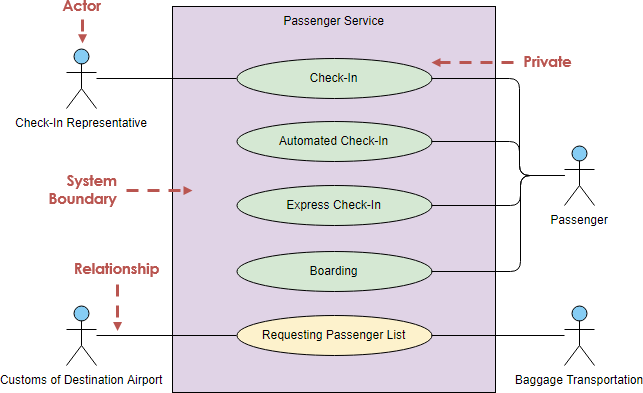
The use case diagram uses four concepts to graphically model the problem domain: use case, actor, relationship link and boundary.
Use case: an ellipse marked with the name of the use case. By convention, we start each use case name with a verb to indicate that the use case represents a process. Therefore, we use “maintain customer list” instead of “customer list”, and “process query” instead of “query”.
An actor: a simple stick-figure with the actor’s name. We capitalize the actor’s name for easy identification (e.g. Librarian, Student).
Actors can be people, other systems, time triggers, or event triggers. An actor specifies a role played by a user or any other system that interacts with the subject. It may represent roles played by human users, external hardware, or other subjects.
Use case relationship: a line connecting actors to use cases. This line shows us which actors are associated with which use cases. This relationship is also called communication.
Boundaries: A rectangle drawn around the use cases that separates them from the actors for describing the scope of the system. System boundaries are optional and often ignored.
Purpose of Use Case Diagram
Use case modeling is done at different stages of the object-oriented software development process. The level of detail and type of information displayed in each phase depends on the purpose of the model. Information related to the detailed design or implementation of the system is not included in the early stages, when the primary purpose is to communicate with users. Later, technical details, such as user interface design, will be added for programmers’ reference.
Use Case vs Class Diagram in System Development
It is important to realize that although the use case model divides and structure the system requirements, this structure is not used as the basis for building new software systems which is, in fact, provided by class diagrams.
The use case model constructs the system as the user’s main task view.
Class diagrams construct systems by using a set of logical software components (objects).
UML Diagrams
- What is UML?
- Why UML Modeling?
- Overview of the 14 UML Diagram Types
- What is Class Diagram?
- What is Component Diagram?
- What is Deployment Diagram?
- What is Object Diagram?
- What is Package Diagram?
- What is Composite Structure Diagram?
- What is Profile Diagram?
- What is Use Case Diagram?
- What is Activity Diagram?
- What is State Machine Diagram?
- What is Sequence Diagram?
- What is Communication Diagram?
- What is Interaction Overview Diagram?
- What is Timing Diagram
This post is also available in Deutsch, Español, فارسی, Français, English, Bahasa Indonesia, 日本語, Polski, Portuguese, Ру́сский, Việt Nam, 简体中文 and 繁體中文.