


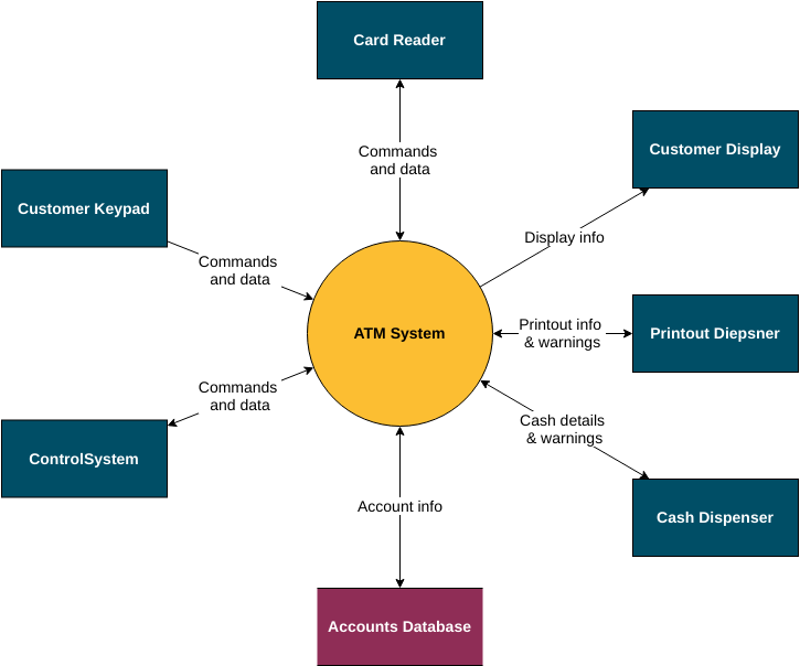
The system context diagram (also known as level 0 DFD) is the highest level in the data flow diagram and contains only a single process representing the entire system that establishes the context and boundaries of the system to be modeled. It identifies the flow of information between the system and external entities, namely actors.
Context diagrams are usually included in requirements documents. It must be read by all stakeholders and should therefore be written in plain language so that the stakeholders can understand the project.
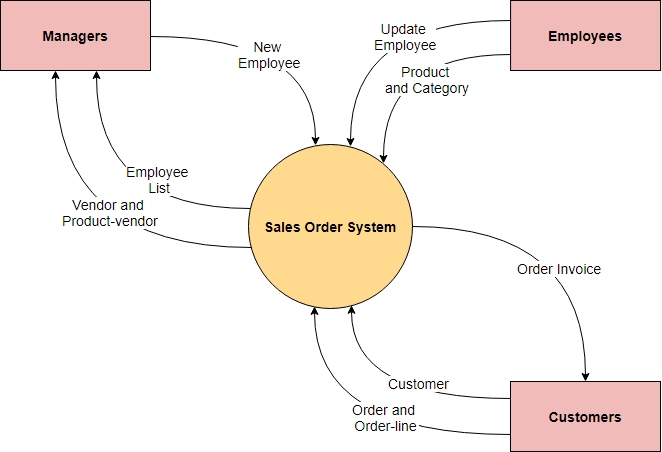
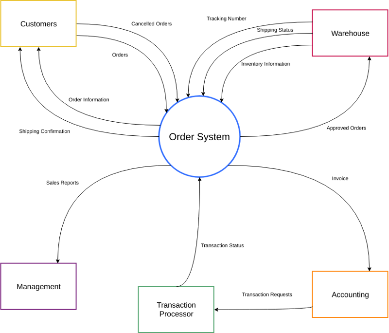
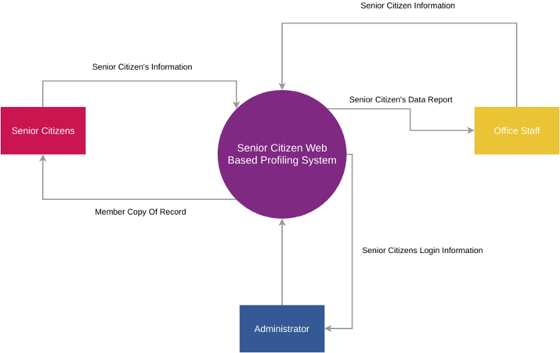
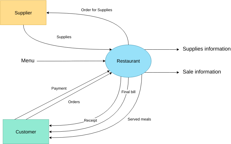
Here is an example context diagram for a Sale Order System:
The purpose of the system context diagram
The goal of a system context diagram is to focus attention on external factors and events that should be considered when developing a set of system requirements and constraints. System context maps are often used early in a project to determine the scope of the investigation.
A system context diagram represents all external entities that may interact with the system. The entire software system looks like a single process. Such a diagram depicts a system at the center, without the details of its internal structure, surrounded by all external entities and interactive systems in the environment.
What is Top-Down Decomposition?
In the top-down design, the overview of the system is designed, specifying but not detailing any level of subsystem. Then, each subsystem is refined in more detail, for example, sometimes divided into many different subsystem levels, so as to decompose the whole specification into basic elements.
The main purpose of top-down design is to decompose a system into smaller parts in order to understand its subsystems. Once these basic elements are identified, they can be more easily built into computer modules. Once the modules are built, you can easily put them together and build the entire system from these individual elements.
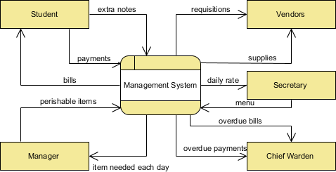
Top-Level Context-Level Diagram
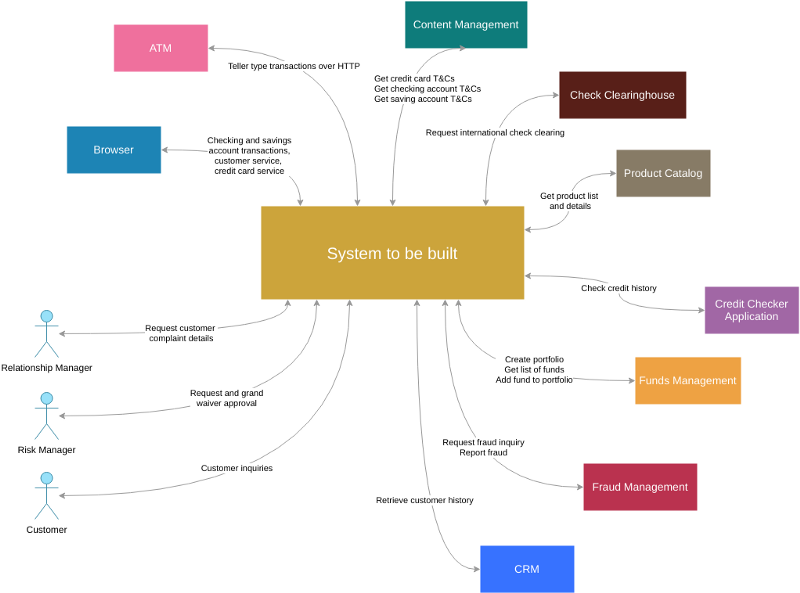
A context diagram gives an overview and it is the highest level in a data flow diagram, containing only one process representing the entire system. It should be split into major processes which give greater detail and each major process may further split to give more detail.
- All external entities are shown on the context diagram as well as major data flow to and from them.
- The diagram does not contain any data storage.
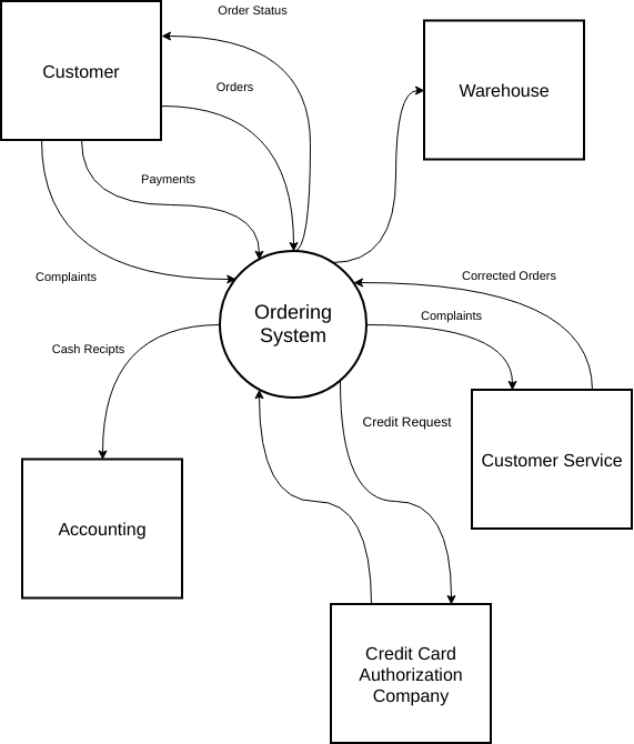
- The single process in the context-level diagram, representing the entire system, can be exploded to include the major processes of the system in the next level diagram, which is termed as diagram 0.
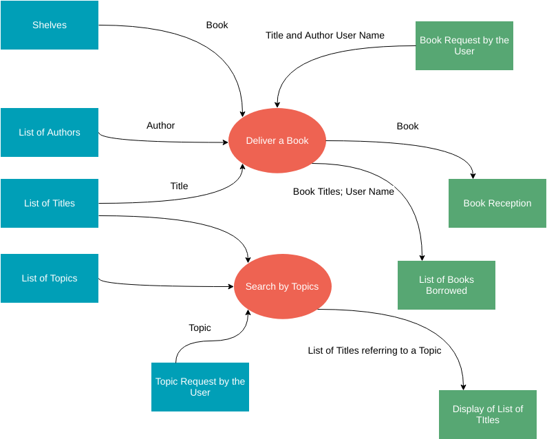
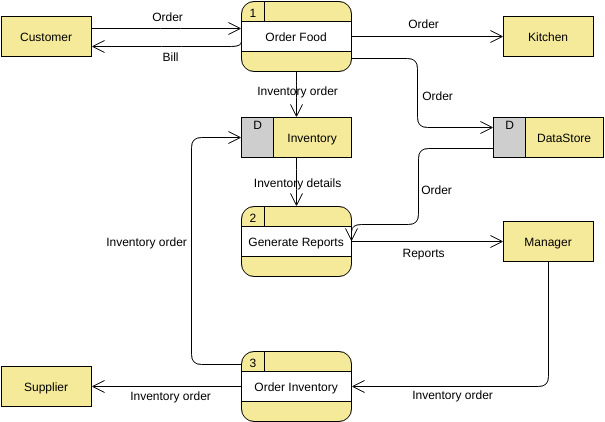
Level 1 DFD
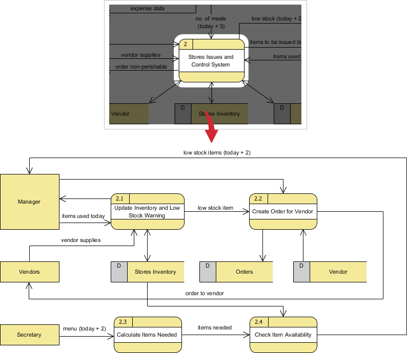
Processes in diagram 0 (with a whole number) can be exploded further to represent details of the processing activities. Example below shows the next level ((Diagram 1) of process explosion.
Note that:
Although the following level 1 DFD only has three processes, there are quite a few input and input from the processes to the external entities and that could end up to be a few cross lines among them in the diagram; to avoid this problem, we could use (master and auxiliary view) multiple views of the same external entity in the DFD.

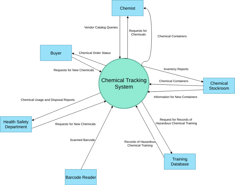
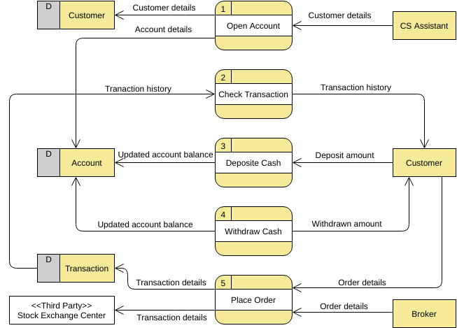
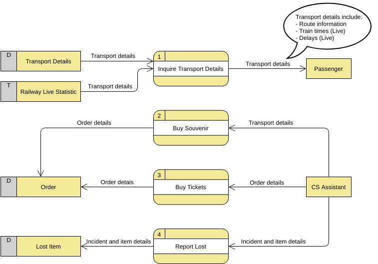
Level 2 DFD
If a process with a lot of data flow linking between a few external entities, we could first extract that particular process and the associated external entities into a separate diagram similar to a context diagram, before you refine the process into a separate level of DFD; and by this way you can ensure the consistency between them much easier.
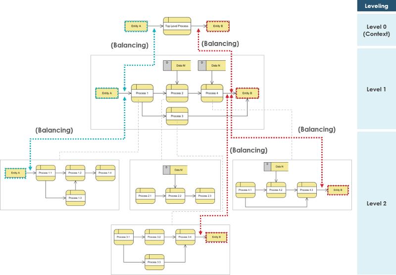
Model Consistency of DFD Between Levels
When performing top-down decomposition to a DFD to lower level DFDs, the inputs and outputs must be conserved between levels of DFDs. For example, level n & n+1 must have the same inputs and outputs
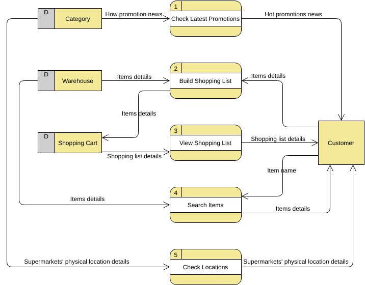
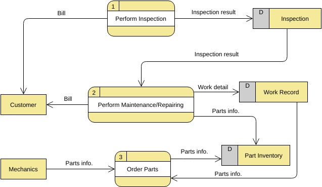
Learn More by Examples
Need some inspiration? Here are some Data Flow Diagram examples below to help you get started.
Click on a diagram to view it, or click the edit button to start editing.
(*Powered by Visual Paradigm Online)

This post is also available in Deutsch, Español, فارسی, Français, English, Bahasa Indonesia, 日本語, Polski, Portuguese, Ру́сский, Việt Nam, 简体中文 and 繁體中文.