


What is a Use Case Diagram?
UML use case diagrams are the primary form of system/software requirements for new software programs under development. The purpose of a use case diagram is to visualize what the system should do (what); at this stage, it does not consider how (how) to do it.
Once a use case is specified, it can be represented in a textual and visual representation (i.e., a case diagram). A key concept of use case modeling is that it helps us to design the system from the end-user’s perspective. It is an effective technique to communicate system behavior in user terms by specifying all externally visible system behaviors.
In other words, the use of the system must be viewed from the outside, that is, the system should not be viewed from the inside, but from a higher level to determine the functionality that the system should provide to the external actors.
Purpose of use case diagrams
Use case diagrams are usually developed in the early stages of development, and people often use use case modeling for the following purposes.
- Specify the context of a system
- Capture the requirements of a system
- Validate the architecture of a system
- Drive implementation and generate test cases
- Develop by analysts, domain experts and target end users together
A standard form of use case diagram is defined in the Unified Modeling Language, as shown in the example of a use case diagram below.
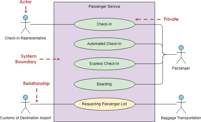
Edit this Use Case Diagram example
Elements of Use Case Diagram
Actors
Each use case will have at least one actor, which can be understood as at least one participant (role), which is not necessarily a person, but may be another system or device. An actor can interact with more than one use case, and a use case can interact with more than one actor.
Actors are not necessarily people, i.e. users, but they can actually be non-people, i.e. systems or time.
Most often, users are people, who are involved in the use case diagram, such as customers, employees, supervisors, etc.
Human vs Non-Human Actors
From time to time, the system is affected by various events to perform certain functions in a given situation. For example, when an audit is passed, the system proactively sends a letter to notify people; so is the sending of the letter performed automatically by the system? This use case is actually triggered by time, then the actor is Timer; for example, this use case can be seen as “automatically send a letter at 5:00 every day”, then the actor that triggers this event – sending a letter – is not the system, but actually the Timer Actor
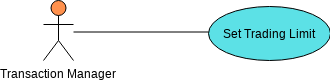
Primary vs Secondary Actors
A primary actor is an actor that uses the system to achieve a goal. Use cases document the interactions between the system and actors to achieve the goals of the primary actor. Secondary actors are the actors that the system needs to assist in order to achieve the goals of the primary actor.
- Actors may be primary or secondary. Primary actors initiate interactions with the system.
- Secondary actors are typically called upon by the system for help and a secondary actor never initiates the use case.
Note that: The symbol for an actor does not differentiate between a primary actor and a secondary actor; the difference must be inferred from the use case descriptions (also called use case narratives).
For Example:
A bank loan officer wants to review a customer’s loan application, and part of the process involves a real-time credit rating check.
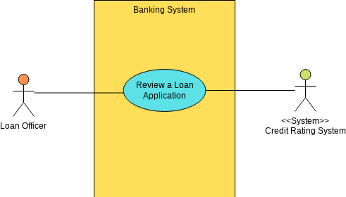
Edit this Use Case Diagram example
- Use Case Name. Review a loan application
- Primary Actor. Loan Officer
- Secondary Actor. Credit rating system
How do I identify actors?
Since an actor is not necessarily a person, but may be a external system, devise or a timer, we find a more specific actor by asking the following questions
- Who will use the system once it has been developed?
- From whom or what other systems will the system need to obtain data?
- Who or what other systems will the system provide data for?
- What other systems will the system be associated with?
- Who will maintain and administer the system?
These questions help us abstract the actors of the system. Using ATMs as an example, answering these questions allows us to find more actors, i.e.
- The operator is responsible for maintaining and managing the ATM system
- ATMs also need to communicate with back-end servers to obtain information about user accounts.
Use Case
A use case represents a functionality (usually a requirement) that is expected to be implemented by the system. The details of a use case, other than its unique name, are not represented visually in the diagram; these details are given in the narrative (textual description) of the use case.
A use case is a list of actions or event steps that typically define the interactions between the actors’ roles and the system to achieve a goal. Use cases are a useful technique for identifying, clarifying and organizing system requirements. A use case consists of a set of sequences of possible interactions between the system and the user that define the functionality to be achieved and the solutions to any errors that may be encountered.
How to Identify Use Cases?
Once we find the actors, we can determine the use cases of the system based on the actors, mainly looking at what services each actor needs from the system, or how the actors use the system. The identification for use cases can start with the following questions (for each participant).
- Why do the actors use the system?
- Does the participant create, modify, delete, access, and store data in the system? If so, how does the actor perform these operations?
- Does the actor notify the system of certain external events?
- Does the system notify the actor of certain internal events?
Putting the above together, the use case diagram of the ATM system can be represented as follows.
Use Case is presented by ellipses, of something static or dynamic, or of a task or a system.
System Boundary
System boundaries describe the system by grouping use cases in rectangular boundaries, and the system boundaries in Visual Paradigm provide the use case containment behavior.
Actors are roles (human actors or non-human actors) that interact with the system under development. Therefore, actors should be placed outside the system boundaries and interact with use cases that are placed within the system boundaries.
Note That:
An actor is defined by the boundaries of the system. If the system boundary we want to define is limited to the ATM itself, then the backend server is an external system and can be abstracted as a actor.
If the system boundary we want to define extends to the whole banking system, where both ATMs and backend servers are part of the whole banking system, then the backend server is no longer abstracted as an actor.
Relationship
After learning about these three key symbols, continue with knowledge of Relationships and drawing use case diagrams. A direct relationship between a participant and a user case is drawn, and the relationship is used as a line with no arrows, indicating a two-way relationship, called a link line.
A use case can be broken down into several use cases that are connected by <<include>>, <<extend>> or <<generalization>> relationships (described later in this post).
Communication Link Relationship
This represents a two-way communication between an actor and a use case and hence is a binary relation.
Edit this Use Case Diagram example
<<Include>> Relationship
An include relationship means that the use case will include other use cases. The purpose of Include Relationship is to use Include Relationship to reduce the repetition of describing the same use case again. If many cases share the same portion function, then the function can be separated out and other use cases can be included in the case.
For example, the librarian needs to read the code to record the borrowed book when the book is checked out, and also needs to read the code to record the returned book when the book is returned, since reading the code is a repetitive portion of action, it can be made into a separate use case, and let the borrowed book and returned book include this case.
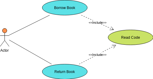
Edit this Use Case Diagram example
If a use case A includes another use case B, then the implementation of A requires the implementation of B to complete its task. However, B is independent of itself. That is, B does not need to know anything about A. B can also be included in any other use case.
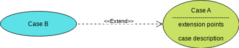
<<Extend>> Relationship
If a use case B extends another use case A, then the implementation of A can conditionally include the implementation of B to complete its task. That is, in some cases, A can complete its task without B. However, depending on the conditions described, A may require B. In this case, B is dependent on B. However, depending on the conditions described, A may require B. In this case, B is dependent on A and cannot exist alone. For this reason, B cannot be extended to more than one use case. The use case narrative of A will include the execution steps it requires from B; this point is called the extension point.
Edit this Use Case Diagram example
Let’s look at another example where the system automatically orders goods when there is no inventory so that the manager doesn’t have to execute the order directly. See the use case diagram below:
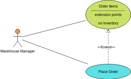
Edit this Use Case Diagram example
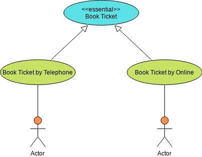
Generalization Relationship
The generalized relationship is similar to the object-oriented language generalized relationship in class diagrams, and can be applied to the generalization of roles (actors) and use cases.
For example, in the booking system, there are two types of booking methods: “book ticket by telephone” and “book ticket by Online”, and the base use case “book ticker”, so you can use generalization to mold the case, and add <<essential>> to the parent use case (booking) to indicate the generalized relationship.
Edit this Use Case Diagram example
Discuss the relationships in the use case diagram
- In a general use case diagram, we only represent the relationships between actors and use cases, i.e., the communication associations between them.
- In addition, we can also describe the generalization between participants and actors, and the include, extend, and generalization relationships between use cases.
- We use these relationships to adapt the existing use case model and extract some common information for reuse, making the use case model easier to maintain.
- However, we have to be careful in choosing these relations in the application. Generally, these relations increase the number of use cases and relations, thus increasing the complexity of the use case model.
- Moreover, the use case model is usually adjusted after it is completed, so there is no need to rush to abstract the relationships between use cases in the early stage of use case modeling.
Use Case – the Flow of Events
The use case diagram gives us an overall view of the system functionality, we can know which participants will interact with the system, and what services each actor needs to get from the system.
The use case describes the conversation between the actors and the system, but the details of this conversation are not represented in the use case diagram, so for each use case we can describe the details of this conversation in terms of an event stream.
Use Case Scenarios and Flow of Events – ATM Withdraw Money
For example, the “Withdrawal” case in an ATM system can be represented by an flow of events as follows:
Normal Scenario – Withdrawal of funds – basic flow of events:
- User inserts credit card
- Enter the PIN
- Enter withdrawal amount
- Withdraws cash
- Exit the system and retrieve the credit card
But this only describes the normal scenario of the withdrawal use case. As a real ATM system, we must also consider various other scenarios that may occur, such as:
- invalid credit cards,
- wrong passwords,
- insufficient cash balance in the user’s account, etc.
All these possible situations (both normal and abnormal) are called scenarios of the use case and scenarios are also called instances of the use case. Scenarios are also referred to as instances of use cases. Among the various scenarios of a use case, the most common scenario is described by the basic process, while other scenarios are described by alternative processes.
Alternative Scenarios
For the “Withdrawal” use case in an ATM system, we can get some alternative processes as follows.
Withdrawal – alternative event processes.
- Alternative scenario I: The user can opt out at any step of the basic process and go to step 5 of the basic process.
- Alternative process II: In step 1 of the basic process, the user inserts an invalid credit card, the system displays an error and exits the credit card, and the use case ends.
- Alternative process III: In step 2 of the basic process, the user enters an incorrect password, the system displays an error and prompts the user to re-enter the password and return to step 2 of the basic process; after three incorrect password entries, the credit card is confiscated by the system and the use case ends.
- …
By combining the basic scenario and the alternative scenarios, all the various situations that can occur in a use case can be clearly described. When describing the flow of events of a use case, we want to describe all possible scenarios as much as possible to ensure the completeness of the requirements.
Use Case Model vs Use Case Diagrams
It is important to avoid the misconception that a use case diagram consisting of actors and use cases is a use case model, because a use case diagram is just a visual representation of the services that the system can provide, giving us a general idea of the functionality of the system.
The use case model consists of a use case diagram and a detailed description of each use case, the use case specification, which is provided as a template in the RUP.
Brief description
A brief description of the role and purpose of the use case.
Flow of Events
Flow of Events should represent all scenarios, including basic and alternative scenarios.
Use Case Scenarios
Include success scenarios and failure scenarios, and scenarios are mainly a combination of basic and alternative flows.
Special Requirements
Describe the non-functional requirements (including performance, reliability, availability, scalability, etc.) and design constraints (operating system, development tools, etc.) associated with the use case.
Pre-Condition
The state that the system must be in before the use case can be executed.
Post-Conditions
The set of states that the system may be in after the use case is executed.
A use case specification is essentially a textual representation, with the option of using state diagrams, activity diagrams, or sequence diagrams to help describe the flow of events more clearly. Any graphical representation of user interfaces and processes, or other graphics, i.e. wireframes, can be attached into the use case as long as they help improve the clarity of the representation.
For example:
- activity diagrams are useful for describing complex decision processes,
- state transition diagrams are useful for describing state-related system behavior, and
- sequence diagrams are appropriate for describing time-based messaging.
Use Case Tools
Online Version
The free drawing tool Visual Paradigm Online (VP Online) free version supports UML, ERD and organizational charts. You can quickly draw use case diagrams with the intuitive UML drawing editor. This free UML tool has no ads, no limited access period, and no restrictions such as number of diagrams, number of shapes, etc. Draw UML freely. Draw UML freely. you own the diagrams you create for personal and non-commercial purposes.
Desktop Version
The Visual Paradigm Community Edition, available since 2004, provides a free UML software for non-commercial purposes only, supporting users who are taking their first steps in UML modeling, as well as those who need a free, cross-platform UML modeling software for personal use, such as applying UML on student projects.
References
- What is Use Case Diagram?
- Types of Actor in Use Case Model
- Identify User Requirements with Use Case Diagrams
- What is Use Case Specification?
- User Story vs Use Case for Agile Software Development
- Use Case Driven Approach for Agile Development
UML Resources
This post is also available in Deutsch, Español, فارسی, Français, English, Bahasa Indonesia, 日本語, Polski, Portuguese, Ру́сский, Việt Nam, 简体中文 and 繁體中文.