


In the complex world of software development and system design, understanding how processes flow and interact is crucial for building robust, efficient applications. Among the various modeling techniques available to architects and developers, UML Activity Diagrams stand out as a powerful visual tool for representing dynamic behavior, workflow coordination, and business process logic. Whether you’re designing a simple application feature or orchestrating enterprise-level workflows, activity diagrams provide the clarity needed to align technical teams, stakeholders, and business analysts around a shared understanding of system behavior.

This comprehensive guide explores the fundamentals of UML Activity Diagrams, demonstrates practical applications through real-world examples, and provides a step-by-step walkthrough for creating professional-quality diagrams. By the end of this article, you’ll have the knowledge and confidence to leverage activity diagrams as a strategic asset in your modeling toolkit—transforming abstract requirements into actionable, visual specifications that drive successful project outcomes.
What is Activity Diagram?
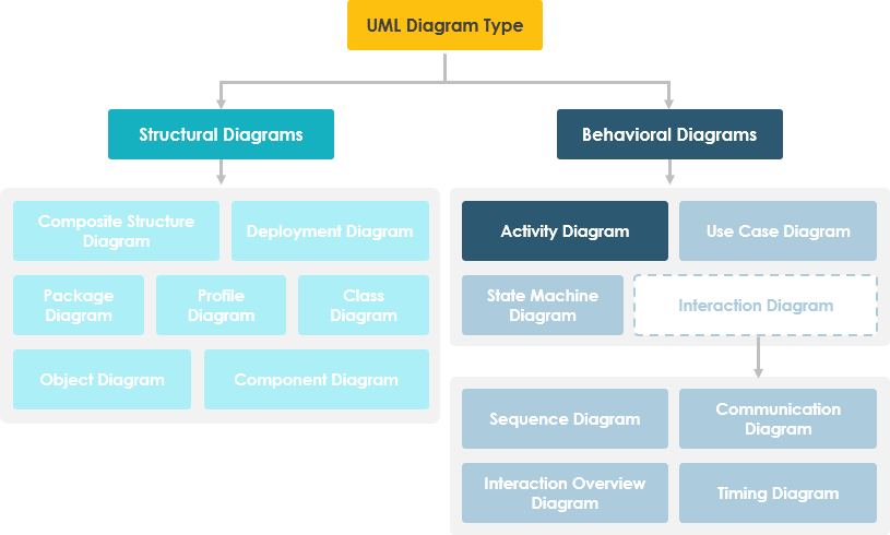
Activity diagram is another important behavioral diagram in UML diagram to describe dynamic aspects of the system. Activity diagram is essentially an advanced version of flow chart that modeling the flow from one activity to another activity.
When to Use Activity Diagram
Activity Diagrams describe how activities are coordinated to provide a service which can be at different levels of abstraction. Typically, an event needs to be achieved by some operations, particularly where the operation is intended to achieve a number of different things that require coordination, or how the events in a single use case relate to one another, in particular, use cases where activities may overlap and require coordination. It is also suitable for modeling how a collection of use cases coordinate to represent business workflows
- Identify candidate use cases, through the examination of business workflows
- Identify pre- and post-conditions (the context) for use cases
- Model workflows between/within use cases
- Model complex workflows in operations on objects
- Model in detail complex activities in a high level activity Diagram
Activity Diagram – Learn by Examples
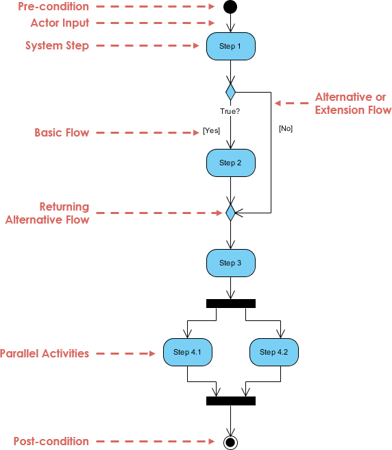
A basic activity diagram – flowchart like
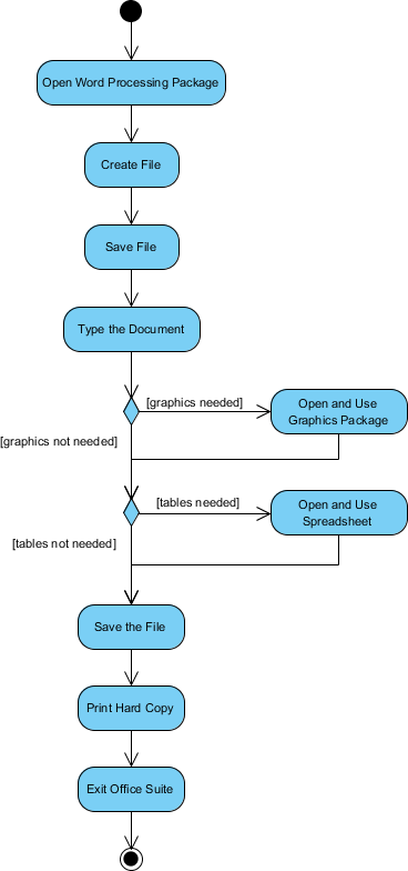
Activity Diagram – Modeling a Word Processor
The activity diagram example below describes the workflow for a word process to create a document through the following steps:
- Open the word processing package.
- Create a file.
- Save the file under a unique name within its directory.
- Type the document.
- If graphics are necessary, open the graphics package, create the graphics, and paste the graphics into the document.
- If a spreadsheet is necessary, open the spreadsheet package, create the spreadsheet, and paste the spreadsheet into the document.
- Save the file.
- Print a hard copy of the document.
- Exit the word processing package.
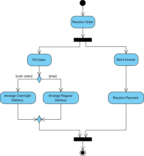
Activity Diagram Example – Process Order
Given the problem description related to the workflow for processing an order, let’s model the description in visual representation using an activity diagram:
| Process Order – Problem Description Once the order is received, the activities split into two parallel sets of activities. One side fills and sends the order while the other handles the billing. On the Fill Order side, the method of delivery is decided conditionally. Depending on the condition either the Overnight Delivery activity or the Regular Delivery activity is performed. Finally the parallel activities combine to close the order. |
|---|
The activity diagram example below visualize the flow in graphical form.
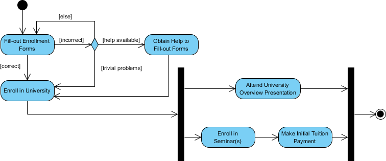
Activity Diagram Example – Student Enrollment
This UML activity diagram example describes a process for student enrollment in a university as follows:
- An applicant wants to enroll in the university.
- The applicant hands a filled out copy of Enrollment Form.
- The registrar inspects the forms.
- The registrar determines that the forms have been filled out properly.
- The registrar informs student to attend in university overview presentation.
- The registrar helps the student to enroll in seminars
- The registrar asks the student to pay for the initial tuition.
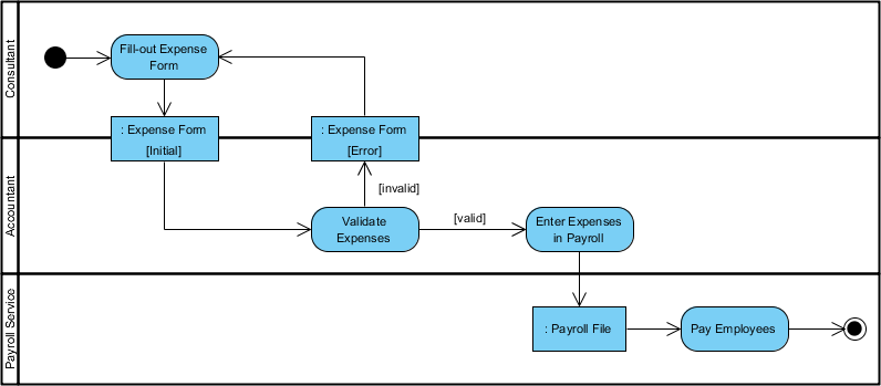
Activity Diagram – Swimlane
A swimlane is a way to group activities performed by the same actor on an activity diagram or activity diagram or to group activities in a single thread. Here is an example of a Swimlane activity diagram for modeling Staff Expenses Submission:
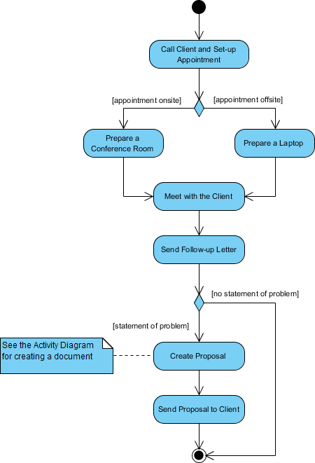
Swimlane and Non-Swimlane Activity Diagram
The activity diagram example below describes the business process for meeting a new client using an activity Diagram without Swimlane.
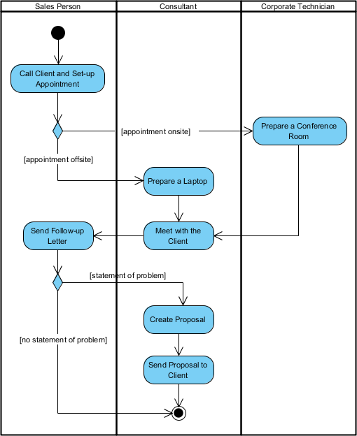
This figure below describes the business process for meeting a new client using an activity Diagram with Swimlane.
Activity Diagram Notation Summary
| Notation Description | UML Notation |
|---|---|
| Activity Is used to represent a set of actions |
 |
| Action A task to be performed |
 |
| Control Flow Shows the sequence of execution |
 |
| Object Flow Show the flow of an object from one activity (or action) to another activity (or action). |
 |
| Initial Node Portrays the beginning of a set of actions or activities |
 |
| Activity Final Node Stop all control flows and object flows in an activity (or action) |
 |
| Object Node Represent an object that is connected to a set of Object Flows |
 |
| Decision Node Represent a test condition to ensure that the control flow or object flow only goes down one path |
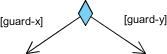 |
| Merge Node Bring back together different decision paths that were created using a decision-node. |
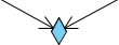 |
| Fork Node Split behavior into a set of parallel or concurrent flows of activities (or actions) |
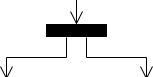 |
| Join Node Bring back together a set of parallel or concurrent flows of activities (or actions). |
 |
| Swimlane and Partition A way to group activities performed by the same actor on an activity diagram or to group activities in a single thread |
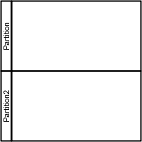 |
How to Draw an Activity Diagram in UML?
Activity Diagrams consist of activities, states and transitions between activities and states which describe how activities are coordinated to provide a service, such as, how the events in a single use case relate to one another, or how a collection of use cases coordinate to create a workflow for an organisation
Steps to develop Activity Diagrams
The steps below outline the major steps to take in creating a UML Activity Diagram.
- Finding system Actors, Classes and use cases
- Identifying key scenarios of system use cases
- Combining the scenarios to produce comprehensive workflows described using activity diagrams
- Where significant object behavior is triggered by a workflow, adding object flows to the diagrams
- Where workflows cross technology boundaries, using swimlanes to map the activities
- Refining complicated high level activities similarly, nested activity diagrams
Creating an Activity Diagram
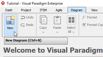
- Click New > New Diagram form the toolbar.
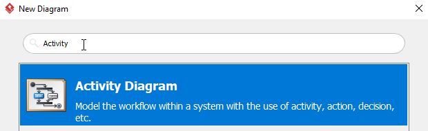
- In the New Diagram window, select Activity Diagram, then click Next. You can use the search bar above to filter diagrams.
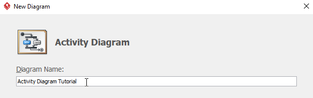
- Name the diagram, then click OK. In this tutorial, the diagram will be named Activity Diagram Tutorial. You will then see an empty diagram.
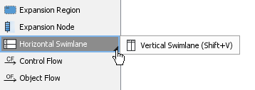
- Select Vertical Swimlane, then click any empty space on the diagram.
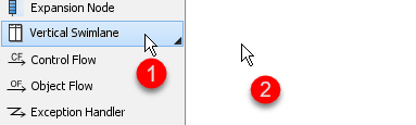
If you cannot findVertical Swimlane, try click the small triangle next to Horizontal Swimelane, you will then see Vertical Swimlane.
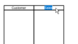
- You can rename partitions by double clicking the name of each partition. The first two participants in this tutorial are Customer and Sales.
- To create more partitions, right click any empty space on the swimlane, then select Add Vertical Partition.
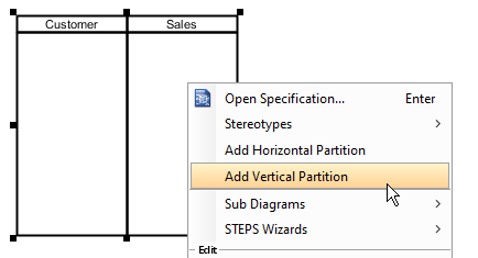
- Repeat step 6 for more partitions.
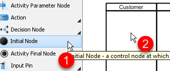
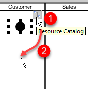
- Create the initial node by selecting Initial Node, then click on the participant where you want the activity starts. In this tutorial, we would like like the activity starts from the Customer participant.
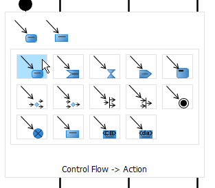
- To create an action, click the initial node, click and hold the resource button, then drag to the desire location. When release the button, choose Control Flow > Action. You can rename the action afterwards by double clicking the action.
- Create more activities using step 9.
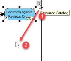
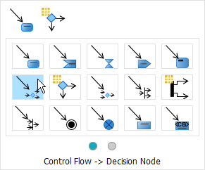
- When creating a decision node, click action that you would like to connect with (Contracts Agents Reviews Order in this example) , click and hold the resource button, then drag to the desire location and release. Choose Control Flow > Decision Node on the popup window. You are allowed drag and move the caption of a decision node.
- Repeat step 11 when creating more decision nodes.
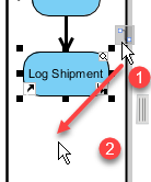
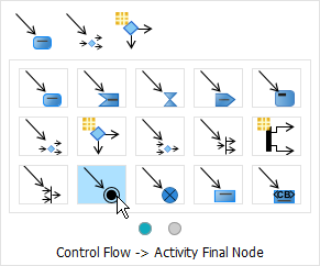
- To create an activity final node, select the final action (Log Shipment in this case) , click the resource button, then drag to the desire position and release. Choose Control Flow > Activity Final Node on the popup window.
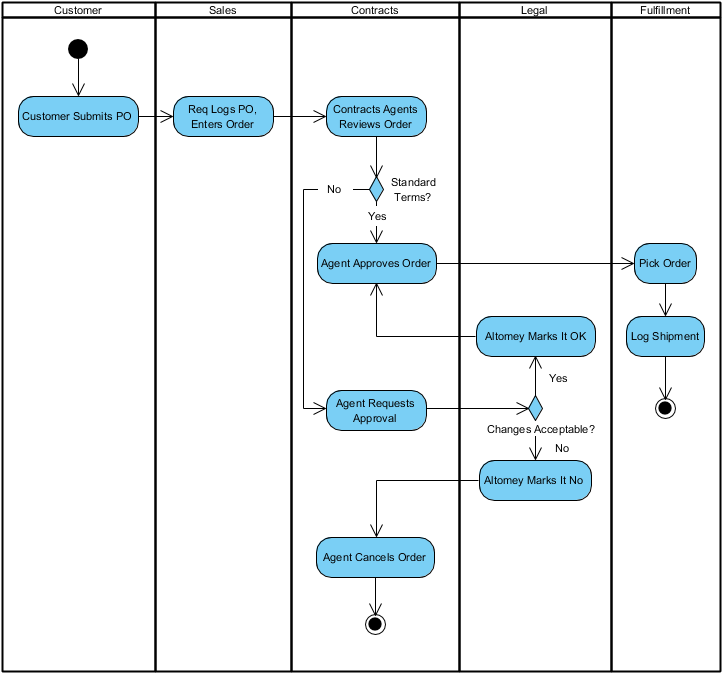
- You will see something similar when finishing your diagram:
Case Study: Streamlining E-Commerce Order Fulfillment with UML Activity Diagrams
Background
GlobalRetail Inc., a mid-sized e-commerce company, was experiencing significant delays and errors in their order fulfillment process. Customer complaints about late deliveries, incorrect items, and billing discrepancies were increasing. The operations team struggled to pinpoint bottlenecks because the workflow existed only in fragmented documentation and team members’ minds. Leadership commissioned a process optimization initiative with a clear goal: visualize, analyze, and improve the end-to-end order fulfillment workflow.
Challenge
The existing process involved multiple departments—Customer Service, Inventory Management, Payment Processing, Warehouse Operations, and Shipping—each with their own systems and procedures. Without a unified visual model, handoffs between teams were ambiguous, parallel tasks weren’t properly coordinated, and exception handling (like payment failures or out-of-stock items) was reactive rather than proactive. The team needed a tool to:
- Map the complete workflow from order placement to delivery confirmation
- Clarify responsibilities across departments
- Identify decision points and parallel processing opportunities
- Document error handling and recovery paths
- Serve as a living reference for training and continuous improvement
Solution: Modeling with Activity Diagrams
The project team adopted UML Activity Diagrams as their primary modeling technique. Using Visual Paradigm, they collaborated with stakeholders from each department to build a comprehensive activity diagram of the order fulfillment process.
Key Modeling Decisions:
- Swimlanes for Role Clarity: Each department was assigned a swimlane, making ownership of activities explicit and highlighting handoff points.
- Parallel Flows for Efficiency: The diagram used fork and join nodes to model parallel processing—payment verification and inventory reservation could occur simultaneously, reducing overall cycle time.
- Decision Nodes for Exception Handling: Clear decision points were added for common scenarios: payment approval, stock availability, shipping method selection, and delivery confirmation.
- Object Flows for Data Tracking: Critical data objects (Order, Payment Receipt, Packing Slip, Tracking Number) were modeled with object flows to show how information moved through the system.
- Nested Activities for Complexity Management: High-level activities like “Process Payment” were refined into sub-diagrams, allowing the team to drill down into details without cluttering the main workflow.
The Resulting Diagram captured the complete workflow:
- Customer places order → System validates cart → Payment processed (parallel with inventory check) → If payment fails, trigger retry or cancellation path → If items in stock, reserve inventory; if not, initiate backorder or substitution workflow → Warehouse picks and packs items → Shipping label generated → Carrier notified → Tracking information sent to customer → Order marked complete → Feedback loop for customer satisfaction survey
Implementation & Outcomes
With the activity diagram as a blueprint, GlobalRetail implemented targeted improvements:
- Automated handoffs between systems reduced manual data entry errors by 73%
- Parallel processing of payment and inventory checks cut average order processing time from 4.2 hours to 1.8 hours
- Clear exception paths reduced “stuck order” incidents by 89%
- The visual diagram became an onboarding tool for new team members, reducing training time by 40%
Most importantly, the activity diagram evolved into a living artifact. As business rules changed (new payment methods, expanded shipping partners, holiday surge protocols), the diagram was updated collaboratively, ensuring all stakeholders maintained a shared understanding of the process.
Lessons Learned
- Start High-Level, Then Refine: Beginning with a simplified workflow helped secure stakeholder buy-in before diving into complex details.
- Involve Cross-Functional Teams Early: Including representatives from each department during modeling ensured accuracy and fostered ownership of the final process.
- Balance Detail with Clarity: Using nested diagrams allowed the team to maintain readability while preserving necessary complexity.
- Treat Diagrams as Living Documents: Establishing a review cadence kept the model aligned with actual operations.
This case demonstrates how UML Activity Diagrams transcend theoretical modeling to become practical instruments for process optimization, team alignment, and continuous improvement in real-world business contexts.
Conclusion
UML Activity Diagrams represent far more than just another diagram type in a software architect’s toolkit—they are a strategic communication framework that bridges the gap between abstract requirements and concrete implementation. By visually mapping the flow of activities, decisions, parallel processes, and responsibilities, activity diagrams empower teams to design more efficient systems, identify bottlenecks before they impact users, and align technical execution with business objectives.
As demonstrated through practical examples and the GlobalRetail case study, the true power of activity diagrams emerges when they are used collaboratively: bringing together developers, business analysts, operations teams, and stakeholders around a shared visual language. Whether modeling a simple user interaction or orchestrating enterprise-scale workflows, the principles remain consistent—clarity, precision, and adaptability.
In an era where digital transformation demands agility and precision, mastering activity diagrams equips professionals with a versatile skill for turning complex processes into actionable, visual specifications. By integrating these diagrams into your modeling practice, you don’t just document how a system works—you create a foundation for continuous improvement, effective communication, and successful delivery. Start small, iterate often, and let your activity diagrams evolve alongside your projects. The result will be systems that not only function correctly but also adapt gracefully to the changing needs of users and businesses alike.
Reference
- Visual Paradigm: Your Complete Guide to UML Modeling – From Free Beginner Tools to Advanced AI-Powered Solutions: A comprehensive guide covering Visual Paradigm’s UML modeling capabilities from beginner to advanced levels.
- Visual Paradigm – UML, Agile, PMBOK, TOGAF, BPMN and More!: Overview of Visual Paradigm’s feature-rich platform supporting multiple modeling standards and frameworks.
- Hands-On Review of Visual Paradigm’s UML Creation Methods: Practical review examining Visual Paradigm’s approaches to creating UML diagrams.
- Visual Paradigm Official Website: The official platform for Visual Paradigm’s visual modeling and CASE tool solutions.
- UML Tool Features – Visual Paradigm: Detailed feature list for Visual Paradigm’s UML modeling tool supporting all 14 UML 2.x diagram types.
- Overview of the 14 UML Diagram Types: Guide explaining structural and behavioral UML diagram categories.
- User Guide: UML Modeling Documentation: Official user documentation for UML modeling features in Visual Paradigm.
- What is a UML Diagram? – Figma Resource Library: Educational resource explaining UML diagram fundamentals and applications.
- Capture Requirements with Use Cases: Guide on using use case diagrams for requirements elicitation and analysis.
- AI-Assisted UML Class Diagram Generator: Feature page describing AI-powered tools for automated class diagram generation.
- Text-to-Diagram Tutorial Video: Video demonstration of converting text descriptions into UML diagrams.
- What is UML? – Visual Paradigm Guide: Foundational guide explaining Unified Modeling Language concepts and purposes.
- Code Engineering Tools: Overview of round-trip engineering and code generation capabilities.
- Visual Paradigm User Guide: Database Mapping: Documentation on ORM and database modeling features.
- Benefits of Database Engineering: Guide on leveraging database engineering features for application development.
- Visual Paradigm Gallery: Showcase of diagrams and models created with Visual Paradigm.
- Installing Visual Paradigm: Installation guide for setting up Visual Paradigm across different environments.
- Eclipse UML Integration: Documentation on integrating Visual Paradigm with Eclipse IDE.
- Free UML Tool: Information about Visual Paradigm’s free community edition for UML modeling.
- UML Modeling Software Process and Tool: Guide on UML modeling methodologies and tool selection.
- Visual Modeling Tool Features: Feature overview of Visual Paradigm’s visual modeling capabilities.
- UML Tool Solution Page: Solution page highlighting UML tool capabilities for enterprise modeling.
- Visual Paradigm Homepage: Main landing page for Visual Paradigm’s modeling platform.
- UML Tutorial: Step-by-step tutorials for learning UML diagram creation.
- UML Tool – Traditional Chinese: Traditional Chinese language version of the UML tool solution page.
This post is also available in Deutsch, Español, فارسی, Français, English, Bahasa Indonesia, 日本語, Polski, Portuguese, Ру́сский, Việt Nam, 简体中文 and 繁體中文.