


This guide demonstrates how to create the UML state machine diagram for a 3D printer lifecycle (originally provided in PlantUML syntax) using the Visual Paradigm AI Chatbot. Visual Paradigm’s AI Chatbot is a powerful, natural-language-driven tool that generates professional UML diagrams instantly, without requiring manual drawing or deep knowledge of UML syntax. It excels at producing accurate state machine diagrams that adhere to OMG standards.
The chatbot is accessible for free at chat.visual-paradigm.com and supports iterative refinement through conversation.
Key Benefits of Using Visual Paradigm AI Chatbot for UML State Diagrams
- Natural Language Input: Describe the system in plain English—no need to write PlantUML code or drag shapes.
- Standards Compliance: The AI is trained on formal UML rules, ensuring correct notation for states, transitions, initial/final states, and events.
- Iterative Editing: Refine the diagram conversationally (e.g., “Add a pause feature” or “Fix the error handling”).
- Instant Visualization: Generates a clean, editable diagram in seconds.
- Export Options: Download as image, import to Visual Paradigm desktop for advanced editing, or generate documentation.
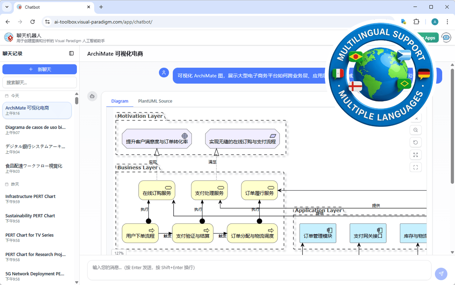
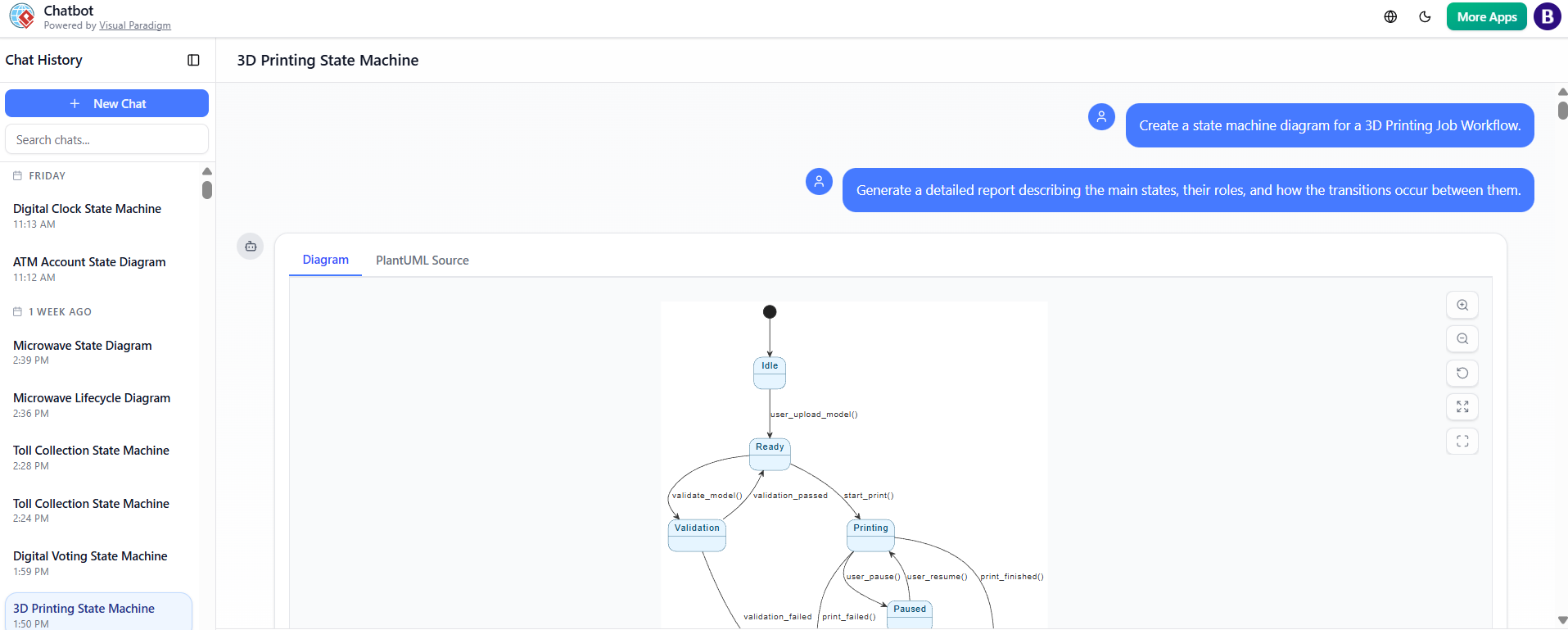
Here are examples of the AI Chatbot interface and generated diagrams:
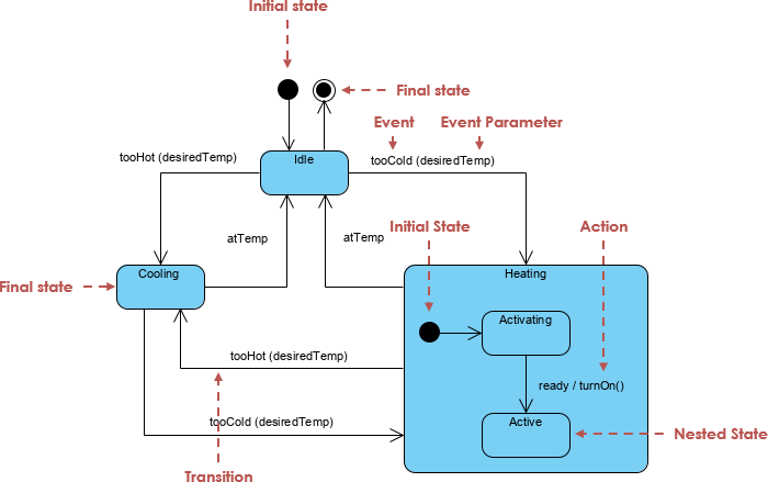
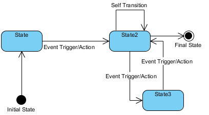
Typical UML state machine diagrams created in Visual Paradigm look like this:
Step-by-Step Guide to Creating the 3D Printer State Diagram
- Access the AI Chatbot
- Go to chat.visual-paradigm.com in your web browser.
- No login is required for basic use (trial mode available), but signing in with a free account unlocks more features and saves your work.
- Start a New Conversation
- Click “New Chat” if needed.
- Begin by specifying the diagram type and providing a description.
- Initial Prompt: Generate the Core Diagram
-
Type a clear natural-language description of the state machine.
-
Recommended prompt for this 3D printer diagram:
“Create a UML state machine diagram for a 3D printer job lifecycle. Start from an initial state to Idle. From Idle, transition to Ready when the user uploads a model. From Ready, go to Validation on model validation. If validation passes, loop back to Ready; if fails, go to Error. From Ready, start printing to go to Printing. During Printing, user can pause to Paused, or print finishes to Completed, or fails to Error. From Paused, resume back to Printing or cancel to Error. Completed and Error are final states.”
-
Press Enter. The AI will instantly generate and display the diagram.
-
- Review and Refine Iteratively
- The chatbot shows the diagram on the right (or in a preview pane) and responds conversationally.
- If needed, refine with follow-up prompts:
- “Add custom styling: light blue background for states and dark blue borders.”
- “Make the Error state red for emphasis.”
- “Add a transition from Printing to Paused on user_pause().”
- “Ensure the initial state is a black circle and final states lead to termination.”
- Each response updates the live diagram while preserving previous elements.
- Enhance with Advanced Features
- Ask for analysis: “Check this state diagram for unreachable states or missing transitions.”
- Request documentation: “Write a step-by-step explanation of this state machine diagram.”
- Add details: “Include guards or actions on transitions, like [validation_failed] for the Error path.”
- Export or Further Edit
- Download the diagram as PNG/SVG.
- If you have Visual Paradigm desktop (Professional Edition or higher), click “Import to Visual Paradigm” to open it for manual tweaks, animation, or code generation.
- Share the chat link for collaboration.
Tips for Best Results
- Be descriptive but concise in prompts—include key states, transitions, and events.
- Use iterative prompts for complex diagrams; the AI maintains context across messages.
- For styling (like the original PlantUML skinparam), mention it explicitly: “Apply skinparam with BackgroundColor #FFFFFF, State BackgroundColor #E6F5FF, BorderColor #005073.”
- The AI handles loops, concurrent states, and history pseudostates if described.
Using Visual Paradigm AI Chatbot, you can go from concept to a polished UML state machine diagram in minutes—far faster than manual tools or coding PlantUML. It’s ideal for prototyping behaviors in systems like 3D printers, IoT devices, or user interfaces. Try it today at chat.visual-paradigm.com!
State Machine Diagram Software Features – Visual ParadigmThis is a direct match as it focuses on Visual Paradigm’s state machine diagram capabilities, which are synonymous with state diagrams in UML. It highlights features for modeling complex state transitions—perfect for users seeking tools to create and manage state diagrams.
Visual Paradigm – UML State Machine Diagram ToolThis link provides an interactive, online tool specifically for creating UML state machine diagrams. It’s highly relevant because it offers real-time diagramming and supports the full lifecycle of state diagram creation, editing, and export.
How to Create a State Machine Diagram in Visual ParadigmA step-by-step guide that directly addresses the process of building state machine diagrams in Visual Paradigm. This is ideal for users who want practical, actionable instructions to implement state diagrams in their projects.
Visual Paradigm: State Machine Diagram User GuideThis comprehensive user guide offers in-depth information on modeling system behavior using state machine diagrams. It’s a strong match for users seeking authoritative, detailed documentation on the topic.
State Diagram Quick Tutorial: Master UML State Machines in MinutesA beginner-friendly tutorial that explains core concepts and practical techniques for creating state diagrams. It’s highly relevant for users new to UML or those looking for a fast, accessible introduction.
Mastering State Diagrams with Visual Paradigm AI: A Guide for Automated Toll SystemsThis article demonstrates advanced use of Visual Paradigm’s AI-enhanced state diagrams in real-world applications. It’s a strong match for users interested in leveraging AI to model complex, dynamic systems like automated toll systems.
Generating Code from State Diagrams in Visual ParadigmThis guide shows how to automate software development by generating code from state diagrams. It’s a valuable resource for developers who want to bridge modeling and implementation using Visual Paradigm’s state diagram functionality.
This post is also available in Deutsch, Español, فارسی, Français, English, Bahasa Indonesia, 日本語, Polski, Portuguese, Ру́сский, Việt Nam, 简体中文 and 繁體中文.