


Infrastructure architecture involves connecting the physical world to the digital requirements of an organization. For architects working within this space, clarity is the primary currency. The challenge often lies not in the complexity of the systems themselves, but in the language used to describe them. Enterprise Architecture frameworks like ArchiMate provide a standardized way to visualize these connections, yet the terminology can sometimes obscure rather than illuminate.
This guide focuses on stripping away the unnecessary complexity. It outlines how to apply ArchiMate concepts specifically to infrastructure environments. By focusing on the Technology Layer and its connections to Application and Business layers, architects can create models that serve operational needs without getting lost in theoretical definitions.
🔧 The Infrastructure Challenge
Infrastructure teams manage servers, networks, storage, and cloud environments. These components are often treated in isolation. A server is managed by one team, a network by another, and security by a third. This siloed approach creates gaps in visibility. When a service goes down, understanding the root cause requires tracing dependencies across these boundaries.
Without a unified model, documentation becomes fragmented. Spreadsheets, network diagrams, and configuration management databases often tell different stories. An architecture framework bridges these gaps. It forces a conversation about how components relate to each other. It moves the discussion from “what is this server?” to “what business capability does this server enable?”.
For the infrastructure architect, the goal is not to model every switch and cable. The goal is to model the flow of value. This means identifying which technology components are critical for service delivery and which are supportive. ArchiMate provides the vocabulary to make these distinctions clear.
🏛️ Core ArchiMate Layers Simplified
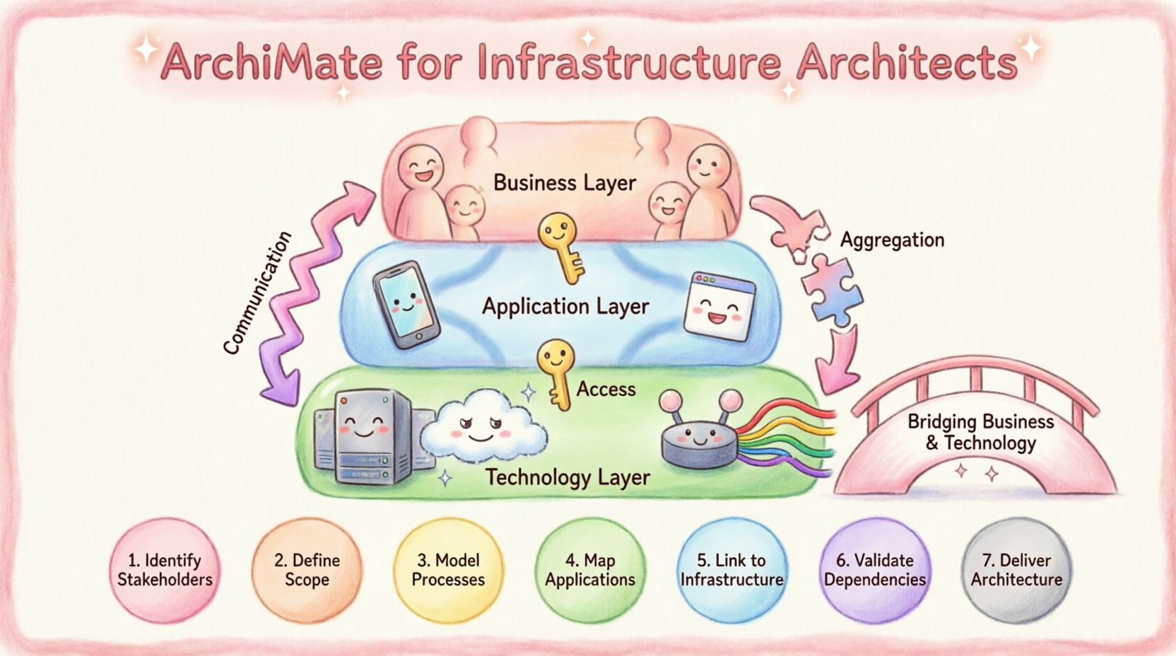
ArchiMate divides the architecture into layers. Understanding these layers helps organize thoughts. While the Business and Application layers are well-known, the Technology Layer is where infrastructure architects spend most of their time.
- Business Layer: Focuses on people, roles, and activities. It defines what the organization does.
- Application Layer: Focuses on software services and capabilities. It defines how the organization processes information.
- Technology Layer: Focuses on hardware, network, and physical infrastructure. It defines where the application runs.
Infrastructure mapping primarily happens in the Technology Layer, but its true value emerges when linked to the layers above. An infrastructure model is incomplete if it does not show how the hardware supports the software, and how the software supports the business.
🔗 The Technology Layer
This layer represents the physical and logical computing environment. It includes devices, systems, and network connections. When mapping infrastructure, architects must distinguish between logical groupings and physical reality. A logical server cluster might span multiple physical locations. A single physical device might host multiple virtual instances.
Keeping this distinction clear prevents confusion during capacity planning or disaster recovery exercises. The model should reflect the deployment reality, not just the logical design.
🧱 Technology Layer Building Blocks
ArchiMate defines specific elements for the Technology Layer. Using these elements correctly ensures consistency. Below is a breakdown of the key building blocks relevant to infrastructure.
| Element | Definition | Infrastructure Context |
|---|---|---|
| Technology Node | A physical or logical location where technology components reside. | Data center, cloud region, or specific rack. |
| Device | A hardware device used for processing or storage. | Server, storage array, firewall, router. |
| System Software | Software that manages hardware resources. | Operating System, Hypervisor, Database Engine. |
| Communication Network | A set of nodes and devices connected by communication paths. | VLAN, Subnet, WAN connection, Internet backbone. |
| Interface Point | A point where a component connects to the outside. | Network port, API endpoint, Storage LUN. |
When creating a model, start with the Technology Node. This establishes the boundary. Then place Devices within that Node. This hierarchy clarifies ownership and physical location. For example, a specific Device might belong to a specific Technology Node representing a specific Availability Zone.
System Software sits on top of the Device. This relationship is crucial for patch management and licensing. It shows which operating system runs on which hardware. If a hardware component fails, the model immediately reveals the software stack affected.
🔄 Defining Relationships and Flows
Components alone are static. Relationships define the dynamics of the system. In infrastructure, understanding how data and control signals move is essential. ArchiMate offers several relationship types to describe these interactions.
📡 Communication Flow
This relationship shows the flow of information between two components. It is directional. For infrastructure, this often represents network traffic. A switch sends packets to a router. A server sends requests to a load balancer.
- Direction: Must be clear. Traffic flows from Source to Target.
- Protocol: While not always modeled explicitly, the nature of the flow implies the protocol (HTTP, TCP, SSH).
- Usage: Helps identify single points of failure. If a node depends on a specific communication path, that path must be redundant.
🔗 Access Relationship
Access is different from flow. Access implies the ability to use a service or resource. It is often used for authentication or authorization scenarios. A user accesses a service. A service accesses a database.
In infrastructure, this maps to logical dependencies. A server does not necessarily “send data” to a storage array in a continuous flow, but it “accesses” the storage for read/write operations. This distinction matters for security modeling. Access relationships often trigger security controls like firewalls or identity management systems.
🔌 Aggregation
Aggregation shows a part-whole relationship. It is a structural link. A Data Center is made of Racks. A Rack is made of Servers. This is useful for asset management.
- Scope: Helps define the boundary of a system. If you remove the part, does the whole cease to function?
- Inventory: Supports accurate asset tracking. You can roll up costs or status from the part to the whole.
🌉 Bridging Business and Technology
Infrastructure models often fail because they remain isolated in the Technology Layer. To be effective, they must connect upward. This connection happens through the Application Layer.
📦 Application Component to System Software
An Application Component is a software module that provides functionality. It runs on System Software. This link is critical for deployment planning. It shows which version of the operating system is required for a specific application to function.
When an application is upgraded, the model reveals if the underlying system software needs to change. This prevents compatibility issues during migration projects.
💼 Business Service to Technology Node
Business Services are the capabilities the organization offers to its customers. Technology Nodes support these services. For example, a “Customer Portal” is a Business Service. It relies on an “Application Cluster” which resides on a “Web Server Node”.
This chain allows for impact analysis. If a specific Technology Node fails, which Business Services are affected? This enables prioritization during incident management. Not all servers are created equal. Some support critical revenue streams, while others support internal tools. The model makes this distinction visible.
⚠️ Common Modeling Pitfalls
Even with a clear framework, mistakes happen. Infrastructure architects should be aware of common traps that reduce the value of the model.
- Over-Modeling: Trying to model every cable and port. This creates noise. Focus on the logical connections that impact service delivery. Physical cabling is often transient and low-value for strategic planning.
- Ignoring Virtualization: Cloud and virtual environments abstract physical hardware. A model based solely on physical racks fails in a cloud-native environment. Use Technology Nodes to represent logical boundaries like Availability Zones or Subnets rather than physical rooms.
- Static Snapshots: Modeling infrastructure as it exists today, but not how it will evolve. Architecture must support change. If a migration is planned, the model should show the target state, not just the current state.
- Disconnected Teams: If the infrastructure team models in one tool and the application team in another, the model fragments. Standards must be shared. Definitions for “Device” or “Node” must be consistent across the organization.
🛠️ Practical Mapping Steps
How does an architect begin the process? A structured approach reduces risk and ensures completeness.
- Define the Scope: Identify the boundaries. Is this for a specific data center? A specific region? A specific cloud account? Start with a manageable boundary.
- Identify Key Nodes: Mark the physical or logical locations where services reside. These are the anchors of the model.
- Place Devices: Populate the Nodes with the hardware or virtual resources. Group them by function (e.g., Compute, Storage, Network).
- Map Software: Assign System Software to Devices. This links the hardware to the capabilities.
- Establish Relationships: Draw the Communication and Access flows. Focus on critical paths that affect service availability.
- Link to Applications: Connect the Technology Layer to the Application Layer. This validates that the infrastructure supports the software.
- Validate with Operations: Review the model with the operations team. Does it match the reality? Are there missing connections? Operations teams know where the bottlenecks are.
🔄 Maintaining Architecture Models
Once the model exists, it becomes a living document. It must be maintained to remain useful. Architecture is not a one-time project. It is a continuous activity.
📝 Change Management Integration
Every change in the infrastructure should trigger a review of the model. When a new server is provisioned, it should be added to the model. When a server is decommissioned, it should be removed. This ensures the model reflects the “Single Source of Truth”.
Integrating this process with the Change Management system is ideal. When a Change Request is approved, the architecture update is part of the acceptance criteria. This prevents “model drift” where the documentation no longer matches the environment.
🔍 Regular Audits
Even with automated processes, humans make mistakes. Regular audits ensure the model remains accurate. These audits can be scheduled quarterly. They should focus on critical paths. If a critical service has a complex dependency chain, verify that chain manually.
Audit findings should feed back into the modeling standards. If a common error is found repeatedly, update the guidelines to prevent it in the future.
📊 Relationship Summary
Understanding the relationships is the key to a functional model. The table below summarizes the primary relationships used in infrastructure mapping.
| Relationship Type | Meaning | Use Case |
|---|---|---|
| Realization | One element realizes another (e.g., Software realizes a Service). | Linking specific software to abstract capabilities. |
| Access | One element uses another. | Database access, API calls, Service dependencies. |
| Communication | Data flow between elements. | Network traffic, Packet transmission. |
| Assignment | One element is assigned to another. | Server assigned to a Cluster, User assigned to a Role. |
| Flow | Information flow between nodes. | Business process steps, Data movement. |
🚀 Future Proofing the Architecture
Technology evolves rapidly. Cloud computing, containerization, and edge computing change how infrastructure looks. The modeling framework must be flexible enough to accommodate these shifts.
Abstracting the model helps. Instead of modeling a specific physical server model, model a “Compute Instance”. This allows the model to remain valid even if the underlying hardware changes from physical to virtual, or from on-premise to cloud. The logical function remains the same, even if the physical implementation changes.
Focus on the service boundaries. As long as the service boundary is clear, the internal details can change without breaking the overall architecture. This approach ensures long-term stability in the face of short-term technological churn.
🤝 Collaboration Across Teams
Architecture is a team sport. The infrastructure model is not owned by one person. It is a shared asset. Collaboration ensures that the model serves everyone.
- DevOps: Needs the model for deployment pipelines. They need to know which environments connect to which databases.
- Security: Needs the model for risk assessment. They need to see where data flows to identify sensitive zones.
- Finance: Needs the model for cost allocation. They need to know which department owns which infrastructure component.
By sharing the model, these teams gain a shared understanding of the environment. This reduces friction during project planning and incident resolution. Everyone works from the same diagram.
🔍 Final Thoughts on Infrastructure Modeling
Building an infrastructure model using ArchiMate concepts requires discipline. It requires focusing on the value of the connections rather than the complexity of the components. When done correctly, the model becomes a powerful tool for decision-making.
It helps answer questions before they become problems. It clarifies who is responsible for what. It identifies risks before they materialize. The effort invested in modeling pays off in reduced downtime and faster resolution times.
The key is consistency. Stick to the definitions. Keep the layers distinct. Ensure the relationships are accurate. Over time, this consistency builds trust in the architecture. Trust allows the team to move faster, knowing the foundation is solid.
Infrastructure architecture is the backbone of digital transformation. By mapping systems clearly, architects provide the stability required for innovation to thrive. The jargon can be set aside. The focus remains on the structure that supports the business.
This post is also available in Deutsch, Español, فارسی, Français, English, Bahasa Indonesia, 日本語, Polski, Portuguese, Ру́сский, Việt Nam, 简体中文 and 繁體中文.