


This article focuses on the concept of UML activity diagram. UML activity diagram is another common tool used by UML to model the dynamic behavior of the system. It describes the sequence of activities and shows the flow of control from one activity to another. UML activity diagram is essentially a flow chart.
UML activity diagram overview
Although both UML activity diagrams and state diagrams are representations of state machines, there are essential differences between the two:
- UML activity diagrams focus on the flow of control from one activity to another, which is an internal processing-driven flow;
- while state diagrams focus on the flow of control from one activity to another. Describe the flow from one state to another, mainly involving the participation of external events.
The difference between UML activity diagram and flowchart
- The flow chart focuses on the description of the processing process. Its main control structure is sequence, branch and cycle. There is a strict sequence and time relationship between each processing process.
- The UML activity diagram describes the rules followed by the sequence relationship of object activities. It focuses on the behavior of the system rather than the process of the system.
- UML activity diagrams can represent the situation of concurrent activities, but flowcharts cannot.
- UML activity diagrams are object-oriented, while flowcharts are process-oriented.
In fact, you can use a basic activity diagram to represent a flowchart, similar to the equivalent diagram:
Graphical representation of UML activity diagram
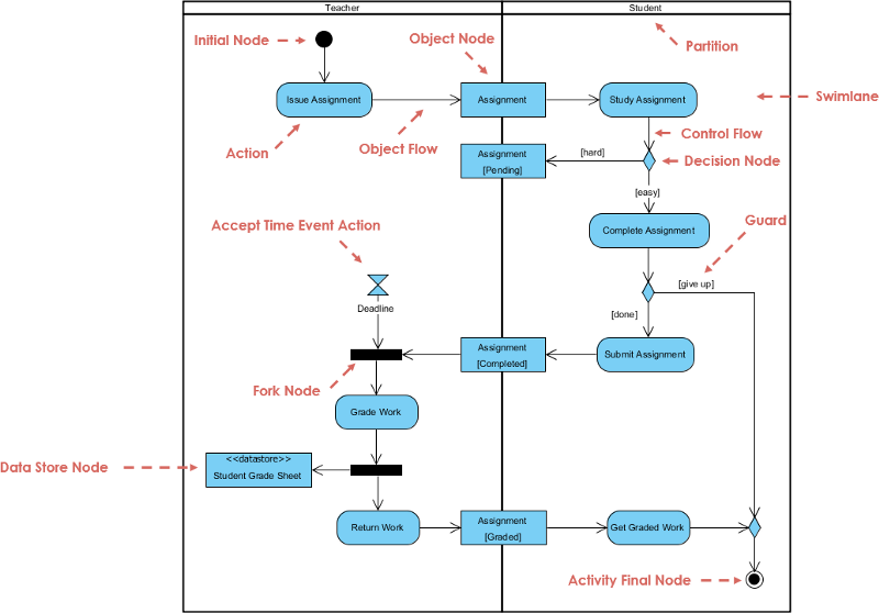
In UML, UML activity diagrams are represented as rounded rectangles.
Activity Diagram Notation Summary
Notation DescriptionUML Notation
Activity — Is used to represent a set of actions

Action — A task to be performed

Control Flow — Shows the sequence of execution

Object Flow — Show the flow of an object from one activity (or action) to another activity (or action).

Initial Node — Portrays the beginning of a set of actions or activities

Activity Final Node — Stop all control flows and object flows in an activity (or action)

Object Node — Represent an object that is connected to a set of Object Flows

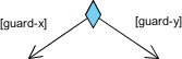
Decision Node — Represent a test condition to ensure that the control flow or object flow only goes down one path
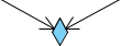
Merge Node — Bring back together different decision paths that were created using a decision-node.
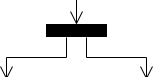
Fork Node — Split behavior into a set of parallel or concurrent flows of activities (or actions)
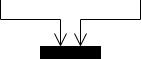
Join Node — Bring back together a set of parallel or concurrent flows of activities (or actions).
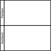
Swimlane and Partition — A way to group activities performed by the same actor on an activity diagram or to group activities in a single thread
More Activity Diagram Examples
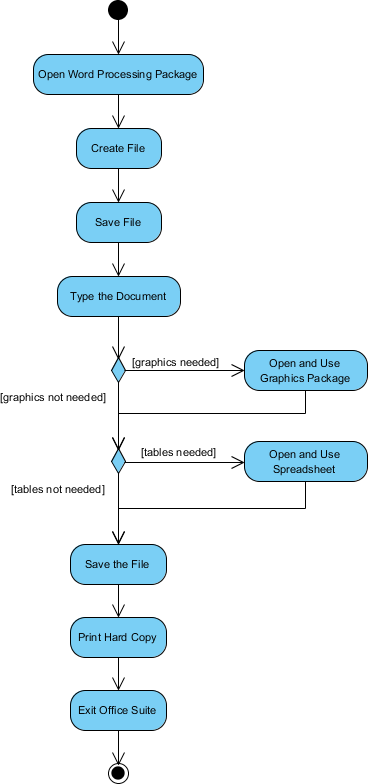
Activity Diagram — Modeling a Word Processor
The activity diagram example below describes the workflow for a word process to create a document through the following steps:
- Open the word processing package.
- Create a file.
- Save the file under a unique name within its directory.
- Type the document.
- If graphics are necessary, open the graphics package, create the graphics, and paste the graphics into the document.
- If a spreadsheet is necessary, open the spreadsheet package, create the spreadsheet, and paste the spreadsheet into the document.
- Save the file.
- Print a hard copy of the document.
- Exit the word processing package.
Activity Diagram Example — Process Order
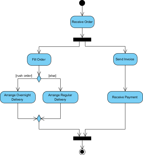
Given the problem description related to the workflow for processing an order, let’s model the description in visual representation using an activity diagram:
Process Order — Problem Description
Once the order is received, the activities split into two parallel sets of activities. One side fills and sends the order while the other handles the billing.
On the Fill Order side, the method of delivery is decided conditionally. Depending on the condition either the Overnight Delivery activity or the Regular Delivery activity is performed.
Finally the parallel activities combine to close the order.
The activity diagram example below visualize the flow in graphical form.
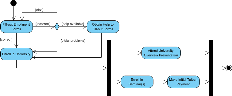
Activity Diagram Example — Student Enrollment
This UML activity diagram example describes a process for student enrollment in a university as follows:
- An applicant wants to enroll in the university.
- The applicant hands a filled out copy of Enrollment Form.
- The registrar inspects the forms.
- The registrar determines that the forms have been filled out properly.
- The registrar informs student to attend in university overview presentation.
- The registrar helps the student to enroll in seminars
- The registrar asks the student to pay for the initial tuition.
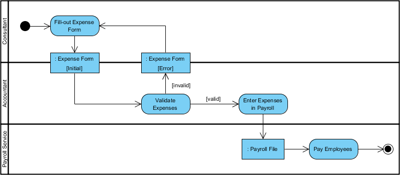
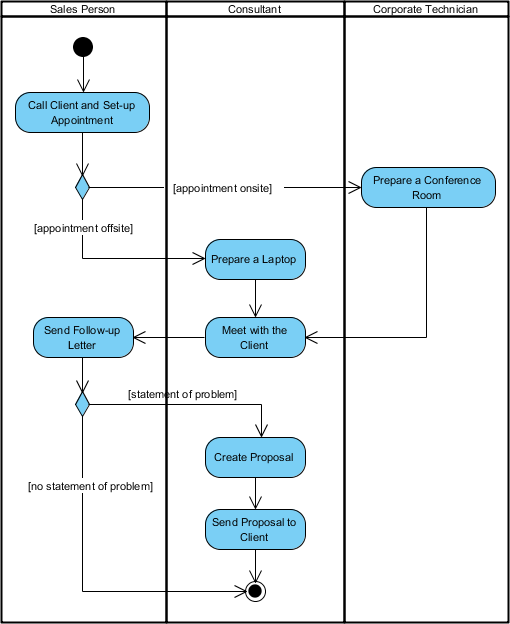
Activity Diagram — Swinlane
A swimlane is a way to group activities performed by the same actor on an activity diagram or activity diagram or to group activities in a single thread. Here is an example of a swinlane activity diagram for modeling Staff Expenses Submission:
Swinlane and Non-Swinlane Activity Diagram
The activity diagram example below describes the business process for meeting a new client using an activity Diagram without swinlane.
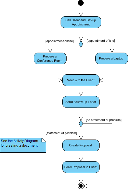
This figure below describes the business process for meeting a new client using an activity Diagram with swinlane.
Learn more about UML diagrams in detail?
- What is UML?
- Why UML Modeling?
- Overview of the 14 UML Diagram Types
- What is Class Diagram?
- What is Component Diagram?
- What is Deployment Diagram?
- What is Object Diagram?
- What is Package Diagram?
- What is Composite Structure Diagram?
- What is Profile Diagram?
- What is Use Case Diagram?
- What is Activity Diagram?
- What is State Machine Diagram?
- What is Sequence Diagram?
- What is Communication Diagram?
- What is Interaction Overview Diagram?
- What is Timing Diagram
- What is UML Collaboration Diagram?
- UML Association vs Aggregation vs Composition
- UML Class Diagram Tutorial
- How to Model Constraints in UML?
- State Machine Diagram vs Activity Diagram
This post is also available in Deutsch, Español, فارسی, Français, English, Bahasa Indonesia, 日本語, Polski, Portuguese, Ру́сский, Việt Nam, 简体中文 and 繁體中文.